ISO 14229-1:2020 Road vehicles — Unified diagnostic services (UDS) — Part 1: Application layer
https://www.iso.org/standard/72439.html
を順に読もう。
ISO 14229-1:2020/DAMD 1 Road vehicles — Unified diagnostic services (UDS) — Part 1: Application layer — Amendment 1
https://www.iso.org/standard/81380.html
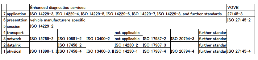
最初は、関係表にある規格群。
markdownでどう表現していいかわからない。
PDF出力して、画像で貼り付け。
ISO Road vehicles Diagnostics 規格調査中 100規格、100記事の方針
https://qiita.com/kaizen_nagoya/items/da41dbb1965ac4be0172
ISO Road vehicles - Diagnostics(11) 百規格百記事をめざし。
https://qiita.com/kaizen_nagoya/items/51e29d318585a4219985
| No. | Title |
|---|---|
| IEEE 802.3 | |
| ISO 10681-2 | ISO 10681-2:2010 Road vehicles — Communication on FlexRay — Part 2: Communication layer services https://www.iso.org/standard/46047.html |
| ISO 11898-1, | ISO/CD 11898-1 Road vehicles — Controller area network (CAN) — Part 1: Data link layer and physical coding sub-layer https://www.iso.org/standard/83292.html |
| ISO 11898-2 | ISO 11898-2:2016 Road vehicles — Controller area network (CAN) — Part 2: High-speed medium access unit https://www.iso.org/standard/67244.html |
| ISO 13400-2 | ISO 13400-2:2019 Road vehicles — Diagnostic communication over Internet Protocol (DoIP) — Part 2: Transport protocol and network layer services https://www.iso.org/standard/74785.html |
| ISO 13400-3, | ISO 13400-3:2016 Road vehicles — Diagnostic communication over Internet Protocol (DoIP) — Part 3: Wired vehicle interface based on IEEE 802.3 https://www.iso.org/standard/68424.html |
| ISO 14229-2 | ISO 14229-2:2021 Road vehicles — Unified diagnostic services (UDS) — Part 2: Session layer services https://www.iso.org/standard/77322.html |
| ISO 14229-4, | ISO 14229-4:2012 Road vehicles — Unified diagnostic services (UDS) — Part 4: Unified diagnostic services on FlexRay implementation (UDSonFR) https://www.iso.org/standard/55285.html |
| ISO 14229-5, | ISO 14229-5:2013 Road vehicles — Unified diagnostic services (UDS) — Part 5: Unified diagnostic services on Internet Protocol implementation (UDSonIP) https://www.iso.org/standard/55287.html |
| ISO 14229-6, | ISO 14229-6:2013 Road vehicles — Unified diagnostic services (UDS) — Part 6: Unified diagnostic services on K-Line implementation (UDSonK-Line) https://www.iso.org/standard/55288.html |
| ISO 14229-7, | ISO 14229-7:2015 Road vehicles — Unified diagnostic services (UDS) — Part 7: UDS on local interconnect network (UDSonLIN) https://www.iso.org/standard/61221.html |
| ISO 14229-8 | ISO 14229-8:2020 Road vehicles — Unified diagnostic services (UDS) — Part 8: UDS on Clock eXtension Peripheral Interface (UDSonCXPI) https://www.iso.org/standard/72527.html |
| ISO 14230-1 | ISO 14230-1:2012 Road vehicles — Diagnostic communication over K-Line (DoK-Line) — Part 1: Physical layer https://www.iso.org/standard/55591.html |
| ISO 14230-2 | ISO 14230-2:2016 Road vehicles — Diagnostic communication over K-Line (DoK-Line) — Part 2: Data link layer https://www.iso.org/standard/69115.html |
| ISO 15765-2 | ISO 15765-2:2016 Road vehicles — Diagnostic communication over Controller Area Network (DoCAN) — Part 2: Transport protocol and network layer services https://www.iso.org/standard/66574.html |
| ISO 17458-2 | ISO 17458-2:2013 Road vehicles — FlexRay communications system — Part 2: Data link layer specification https://www.iso.org/standard/59806.html |
| ISO 17458-4 | ISO 17458-4:2013 Road vehicles — FlexRay communications system — Part 4: Electrical physical layer specification https://www.iso.org/standard/59808.html |
| ISO 17987-2 | ISO 17987-2:2016 Road vehicles — Local Interconnect Network (LIN) — Part 2: Transport protocol and network layer services https://www.iso.org/standard/61223.html |
| ISO 17987-3 | ISO 17987-3:2016 Road vehicles — Local Interconnect Network (LIN) — Part 3: Protocol specification https://www.iso.org/standard/61224.html |
| ISO 17987-4 | ISO 17987-4:2016 Road vehicles — Local Interconnect Network (LIN) — Part 4: Electrical physical layer (EPL) specification 12 V/24 V https://www.iso.org/standard/61225.html |
| ISO 20794-3 | ISO 20794-3:2020 Road vehicles — Clock extension peripheral interface (CXPI) — Part 3: Transport and network layer https://www.iso.org/standard/72869.html |
| ISO 20794-4 | ISO 20794-4:2020 Road vehicles — Clock extension peripheral interface (CXPI) — Part 4: Data link layer and physical layer https://www.iso.org/standard/72870.html |
| ISO 27145-2 | ISO 27145-2:2012 Road vehicles — Implementation of World-Wide Harmonized On-Board Diagnostics (WWH-OBD) communication requirements — Part 2: Common data dictionary https://www.iso.org/standard/46276.html |
| ISO 27145-3 | ISO 27145-3:2012 Road vehicles — Implementation of World-Wide Harmonized On-Board Diagnostics (WWH-OBD) communication requirements — Part 3: Common message dictionary https://www.iso.org/standard/46277.html |
| ISO 27145-4 | ISO 27145-4:2016 Road vehicles — Implementation of World-Wide Harmonized On-Board Diagnostics (WWH-OBD) communication requirements — Part 4: Connection between vehicle and test equipment https://www.iso.org/standard/68571.html |
Contents
次に目次に現れる項目。_16は、その前の数字が16進数であることを示す。
Foreword.
Introduction.
1 Scope
2 Normative references
3 Terms and definitions
4 Symbols and abbreviated terms.
5 Conventions
6 Document overview
7 Application layer services
7.1 General
7.2 Format description of application layer services
7.3 Format description of service primitives
7.3.1 General definition
7.3.2 Service request and service indication primitives
7.3.3 Service response and service confirm primitives.
7.3.4 Service request-confirm and service response-confirm primitives
7.4 Service data unit specification .
7.4.1 Mandatory parameters
7.4.2 Vehicle system requirements
7.4.3 Optional parameters - A_AE,aplicatison-layer-remote address
8 Application layer protocol.
8.1 General definition.
8.2 A_PDU, application protocol data unit
8.3 A_PCI, application protocol control information
8.4 SI, service identifier .
8.5 A_NR_SI, Negative response service identifier
8.6 Negative response/confirmation service primitive.
8.7 Server response implementation rules
8.7.1 General definitions
8.7.2 General server response behaviour
8.7.3 Request message with SubFunction parameter and server response behaviour.
8.7.4 Request message without SubFunction parameter and server response behaviour
8.7.5 Pseudo code example of server response behaviour
8.7.6 Multiple concurrent request messages with physical and functional addressing
9 Service description conventions .
9.1 Service description
9.2 Request message
9.2.1 Request message definition
9.2.2 Request message SubFunction parameter $Level (LEV_) definition .
9.2.3 Request message data-parameter definition .
9.3 Positive response message
9.3.1 Positive response message definition
9.3.2 Positive response message data-parameter definition
9.4 Supported negative response codes (NRC_)
9.5 Message flow examples
10 Diagnostic and communication management functional unit.
10.1 Overview .
10.2 DiagnosticSessionControl (10_16) service .
10.2.1 Servicedescription
10.2.2 Request message
10.2.3 Positiveresponsemessage
10.2.4 Supported negative response codes (NRC_)
10.2.5 Message flow example(s) DiagnosticSessionControl – Start programmingSession
10.3 ECUReset (11_16) service .
10.3.1 Servicedescription
10.3.2 Request message
10.3.3 Positiveresponsemessage
10.3.4 Supported negative response codes (NRC_)
10.3.5 Message flow example ECUReset
10.4 SecurityAccess (27_16) service
10.4.1 Servicedescription
10.4.2 Request message
10.4.3 Positiveresponsemessage
10.4.4 Supported negative response codes (NRC_)
10.4.5 Message flow example(s) SecurityAccess
10.5 CommunicationControl (28_16) service .
10.5.1 Servicedescription
10.5.2 Request message .(standard.sitehai)
10.5.3 Positiveresponsemessage
10.5.4 Supported negative response codes (NRC_)
10.5.5 Message flow examle CommunicationControl(disable transmission network management message)
10.5.6 Message flow example CommunicationControl (switch a remote network into the diagnostic-only scheduling mode where the node with address 000A16 is connected to)
10.5.7 Message flow example CommunicationControl (switch to application scheduling mode with enhanced address information, the node 000A16, which is connected to a sub-network, is addressed)
10.6 Authentication (29_16) service
10.6.1 Service overview
10.6.2 Authentication with PKI Certificate Exchange (APCE)
10.6.3 Authentication with Challenge-Response (ACR)
10.6.4 Commonrequirements
10.6.5 Request message
10.6.6 Positiveresponsemessage
10.6.7 Supported negative response codes (NRC_)
10.6.8 Message flow example(s) Authentication
10.7 TesterPresent (3E_16) service
10.7.1 Servicedescription
10.7.2 Requestmessage
10.7.3 Positiveresponsemessage.
10.7.4 Supportednegativeresponsecodes(NRC_).
10.7.5 Message flow example(s) TesterPresent
10.8 ControlDTCSetting (8516) service.
10.8.1 Servicedescription
10.8.2 Requestmessage
10.8.3 Positive response message.
10.8.4 Supported negative response codes (NRC_).
10.8.5 Message flow example(s) ControlDTCSetting .
10.9 ResponseOnEvent (86_16) service .
10.9.1 Service description
10.9.2 Request message
10.9.3 Positive response message.
10.9.4 Supported negative response codes (NRC_).
10.9.5 Message flow example(s) ResponseOnEvent
10.10 LinkControl (87_16) service
10.10.1 Service description
10.10.2 Request message 1
10.10.3 Positive response message
10.10.4 Supported negative response codes (NRC_)
10.10.5 Message flow example(s) LinkControl
11 Data transmission functional unit
11.1 Overview
11.2 ReadDataByIdentifier (22_16) service
11.2.1 Service description
11.2.2 Request message
11.2.3 Positive response message.
11.2.4 Supported negative response codes (NRC_).
11.2.5 Message flow example ReadDataByIdentifier.
iTeh STANDARD PREVIEW
11.3 ReadMemoryByAddress (23_16) service .
11.3.1 Service description (standard.sitehai)
11.3.2 Request message
11.3.3 Positive response message
11.3.4 Support negative response code(NRC_)
11.3.5 Message flow example ReadMemoryByAddress
11.4 ReadScalingDataByIdentifier (24_16) service
11.4.1 Service description
11.4.2 Request message
11.4.3 Positive response message.
11.4.4 Supported negative response codes (NRC_).
11.4.5 Message flow example ReadScalingDataByIdentifier
11.5 ReadDataByPeriodicIdentifier (2A_16) service.
11.5.1 Service description
11.5.2 Request message
11.5.3 Positive response message.
11.5.4 Supported negative response codes (NRC_).
11.5.5 Message flow example ReadDataByPeriodicIdentifier
11.6 DynamicallyDefineDataIdentifier (2C_16) service
11.6.1 Service description
11.6.2 Request message
11.6.3 Positive response message.
11.6.4 Supported negative response codes (NRC_).
11.6.5 Message flow examples DynamicallyDefineDataIdentifier
11.7 WriteDataByIdentifier (2E16) service.
11.7.1 Service description
11.7.2 Request message
11.7.3 Positive response message.
11.7.4 Supported negative response codes (NRC_).
11.7.5 Message flow example WriteDataByIdentifier
11.8 WriteMemoryByAddress (3D_16) service
11.8.1 Servicedescription
11.8.2 Requestmessage
11.8.3 Positiveresponsemessage.
11.8.4 Supportednegativeresponsecodes(NRC_).
11.8.5 MessageflowexampleWriteMemoryByAddress
12 Stored data transmission functional unit
12.1 Overview
12.2 ClearDiagnosticInformation (14_16) service
12.2.1 Servicedescription
12.2.2 Requestmessage
12.2.3 Positiveresponsemessage.
12.2.4 Supportednegativeresponsecodes(NRC_).
12.2.5 Message flow example ClearDiagnosticInformation.
12.3 ReadDTCInformation (19_16) service
12.3.1 Servicedescription
12.3.2 Requestmessage
12.3.3 Positiveresponsemessage.
12.3.4 Supportednegativeresponsecodes(NRC_).
12.3.5 Message flow examples – ReadDTCInformation.
13 InputOutput control functional unit
13.1 Overview
13.2 InputOutputControlByIdentifier (2F_16) service
13.2.1 Servicedescription
13.2.2 Requestmessage
13.2.3 Positiveresponsemessage.
13.2.4 Supportednegativeresponsecodes(NRC_).
13.2.5 Message flow example(s) InputOutputControlByIdentifier
14 Routine functional unit
14.1 Overview
14.2 RoutineControl (31_16) service
14.2.1 Servicedescription
14.2.2 Requestmessage
14.2.3 Positiveresponsemessage.
14.2.4 Supportednegativeresponsecodes(NRC_).
14.2.5 Messageflowexample(s)RoutineControl
15 Upload download functional unit .
15.1 Overview
15.2 RequestDownload (34_16) service
15.2.1 Servicedescription
15.2.2 Requestmessage
15.2.3 Positiveresponsemessage.
15.2.4 Supportednegativeresponsecodes(NRC_).
15.2.5 Message flow example(s) RequestDownload
15.3 RequestUpload (35_16) service
15.3.1 Servicedescription
15.3.2 Requestmessage
15.3.3 Positiveresponsemessage.
15.3.4 Supportednegativeresponsecodes(NRC_).
15.3.5 Message flow example(s) RequestUpload.
15.4 TransferData (36_16) service
15.4.1 Servicedescription
15.4.2 Request message
15.4.3 Positive response message.
15.4.4 Supported negative response codes (NRC_).
15.4.5 Message flow example(s) TransferData
15.5 RequestTransferExit (3716) service
15.5.1 Service description
15.5.2 Request message
15.5.3 Positive response message.
15.5.4 Supported negative response codes (NRC_).
15.5.5 Message flow example(s) for downloading/uploading data .
15.6 RequestFileTransfer (38_16) service
15.6.1 Service description
15.6.2 Request message
15.6.3 Positive response message.
15.6.4 Supported negative response codes (NRC_).
15.6.5 Message flow example(s) RequestFileTransfer
16 Security sub-layer definition .
16.1 General
16.1.1 Purpose .
16.1.2 Security sub-layer description
16.1.3 Security sub-layer access
16.1.4 General server response behaviour
16.2 SecuredDataTransmission (84_16) service.
16.2.1 Service description
16.2.2 Request message(standard.sitehai)
16.2.3 Positive response message for successful internal message.
16.2.4 Supported negative response code(NRC_)
16.2.5 Message flow
17 Non-volatile server memory programming process
17.1 General information .
17.2 Detailed programming sequence.
17.2.1 Programming phase #1 — Download of application software and/or application
17.3 Server reprogramming requirements
17.3.1 Requirements for servers to support programming
17.3.2 Software, data identification and fingerprints
17.3.3 Serverroutineaccess
17.4 Non-volatile server memory programming message flow examples
17.4.1 Generalinformation.
17.4.2 Programming phase #1 — Pre-Programming step
17.4.3 Programming phase #1 — Programming step
17.4.4 Programming phase #1 — Post-Programming step .
Annex A (normative) Global parameter definitions
Annex B (normative) Diagnostic and communication management functional unit data- parameter definitions
Annex C (normative) Data transmission functional unit data-parameter definitions
Annex D (normative) Stored data transmission functional unit data-parameter definitions
Annex E (normative) Input output control functional unit data-parameter definitions
Annex F (normative) Routine functional unit data-parameter definitions
Annex G (normative) Upload and download functional unit data-parameter
Annex H (informative) Examples for addressAndLengthFormatIdentifier parameter values
Annex I (normative) Security access state chart
Annex J (informative) Recommended implementation for multiple client environments
Bibliography
Normative Reference
ISO 14229-2, Road vehicles — Unified diagnostic services (UDS) — Part 2: Session layer services
ISO 7816-8, Identification cards — Integrated circuit cards — Part 8: Commands and mechanisms for
ISO/IEC 9594-8:2020 Information technology — Open systems interconnection — Part 8: The Directory: Public-key and attribute certificate frameworks
ISO/IEC 9594-8:2020/COR 1:2021
Information technology — Open systems interconnection — Part 8: The Directory: Public-key and attribute certificate frameworks — Technical Corrigendum 1
IEEE 754-2008, IEEE Standard for Floating-Point Arithmetic
suspended by
IEEE 754-2019 - IEEE Standard for Floating-Point Arithmetic
IEEE 1609.2, Standard for Wireless Access in Vehicular Environments — Security Services for Applications and Management Messages
X.509, Information technology — Open Systems Interconnection — The Directory: Public-key and attribute certificate frameworks
ITU-T X.509 TELECOMMUNICATION STANDARDIZATION SECTOR OF ITU
Corrigendum 1 (10/2021)
RFC 5280, Internet Engineering Task Force — Internet X.509 Public Key Infrastructure Certificate and Certificate Revocation List (CRL) Profile
RFC 5755, Internet Engineering Task Force — An Internet Attribute Certificate Profile for Authorization © ISO 2020 – All rights reserved
3 Terms and definitions
用語定義
For the purposes of this document, the following terms and definitions apply.
ISO and IEC maintain terminological databases for use in standardization at the following addresses:
— ISO Online browsing platform: available at https://www.iso.org/obp
— IEC Electropedia: available at http://www.electropedia.org/
3.1 boot memory partition
area of the server (3.18) memory in which the boot software (3.2) is located
3.2 boot software
software which is executed in a special part of server (3.18) memory which is used primarily to boot the ECU (3.9) and perform server programming
Note 1 to entry: This area of memory is not erased during a normal programming sequence and executes when the server application is missing or otherwise deemed invalid to always ensure the capability to reprogram the server.
Note 2 to entry: See 0 and 17.3.1.1.
3.3 client
function that is part of the tester (3.20) and that makes use of the diagnostic services (3.6)
Note 1 to entry: A tester normally makes use of other functions such as data base management, specific interpretation, human-machine interface.
3.4 diagnostic channel
dedicated transmission path from client (3.3) to server (3.18) for diagnostic communication
Note 1 to entry: Several simultaneously connected clients to one server can be differentiated by an individual tester (3.20) source address.
3.5 diagnostic data
data that is located in the memory of an electronic control unit (3.9) which may be inspected and/or possibly modified by the tester (3.20)
Note 1 to entry: Diagnostic data includes analogue inputs and outputs, digital inputs and outputs, intermediate values and various status information.
Note 2 to entry: Examples of diagnostic data are vehicle speed, throttle angle, mirror position, system status, etc. Three types of values are defined for diagnostic data:
— the current value: the value currently used by (or resulting from) the normal operation of the electronic control unit;
— a stored value: an internal copy of the current value made at specific moments (e.g. when a malfunction occurs or periodically); this copy is made under the control of the electronic control unit;
— a static value: e.g. VIN.
The server (3.18) is not obliged to keep internal copies of its data for diagnostic purposes, in which case the tester may only request the current value.
Note 3 to entry: Defining a repair shop or development testing session selects different server functionality (e.g. access to all memory locations may only be allowed in the development testing session).
3.6 diagnostic service
information exchange initiated by a client (3.3) in order to require diagnostic information from a server (3.18) or/and to modify its behaviour for diagnostic purpose
3.7 diagnostic session
state within the server (3.18) in which a specific set of diagnostic services (3.6) and functionality is enabled
3.8 diagnostic trouble code, DTC
numerical common identifier for a fault condition identified by the on-board diagnostic system
3.9 ECU, electronic control unit
unit providing information regarding the connected sensor and control network
Note 1 to entry: Systems considered as electronic control units include anti-lock braking system (ABS) and engine management system.
3.10 functional unit
set of functionally close or complementary diagnostic services (3.6)
3.11 local server
server (3.18) that is connected to the same local network as the client (3.3) and is part of the same address space as the client
3.12 permanent DTC
diagnostic trouble code (3.8) that remains in non-volatile memory, even after a clear DTC request, until other criteria (typically regulatory) are met (e.g. the appropriate monitors for each DTC have successfully passed)
Note 1 to entry: Refer to the relevant legislation for all necessary requirements.
3.13 record
one or more diagnostic data (3.5) elements that are referred to together by a single means of identification
Note 1 to entry: A snapshot including various input/output data and trouble codes is an example of a record.
3.14 remote server
server (3.18) that is not directly connected to the main diagnostic network
Note 1 to entry: A remote server is identified by means of a remote address. Remote addresses represent an own address space that is independent from the addresses on the main network.
Note 2 to entry: A remote server is reached via a local server (3.11) on the main network. Each local server on the main network can act as a gate to one independent set of remote servers. A pair of addresses therefore always identifies a remote server: one local address that identifies the gate to the remote network and one remote address identifying the remote server itself.
3.15 remote client
client (3.3) that is not directly connected to the main diagnostic network
Note 1 to entry: A remote client is identified by means of a remote address.
Note 2 to entry: Remote addresses represent an own address space that is independent from the addresses on the main network.
3.16 reprogramming software
part of the boot software (3.2) that allows for reprogramming of the electronic control unit (3.9)
3.17 security
mechanism for protecting vehicle modules from "unauthorized" intrusion through a vehicle diagnostic data (3.5) link
3.18 server
function that is part of an electronic control unit (3.9) and that provides the diagnostic services (3.6)
Note 1 to entry: This document differentiates between the server (i.e. the function) and the electronic control unit to ensure independence from implementation.
3.19 supported DTC
diagnostic trouble code (3.8) which is currently configured/calibrated and enabled to execute under predefined vehicle conditions.
3.20 tester
system that controls functions such as test, inspection, monitoring, or diagnosis of an on-vehicle electronic control unit (3.9) and can be dedicated to a specific type of operator (e.g. an off-board scan tool dedicated to garage mechanics, an off-board test tool dedicated to assembly plants, or an on-board tester)
Note 1 to entry: The tester is also referenced as the client (3.3).
4 Symbols and abbreviated terms.
.con service primitive .confirmation
.ind service primitive .indication
.req service primitive .request
A_PCI application layer protocol control information
ACR Authentication with Challenge-Response
APCE Authentication with PKI Certificate Exchange
BER Basic Encoding Rules according to ITU-T X.690
CMAC Cipher-based Message Authentication Code
CVC Card Verifiable Certificate
ECU electronic control unit
EDR event data recorder
GMAC Galois Message Authentication Code
HMAC Hash-based Message Authentication Code
N/A not applicable
NR_SI negative response service identifier
NRC negative response code
OID Object Identifier according to ISO/IEC 9834-1
OSI open systems interconnection
PKCS Public-Key Cryptography Standards
PKI Public-Key Infrastructure
POWN Proof of Ownership
RA remote address
SA source address
SI service identifier
TA target address
TA_type target address type
X.509 PKI standard according to ISO/IEC 9594-8
Bibliography
[1] ISO 4092:1988/Cor.1:1991, Road vehicles — Diagnostic systems for motor vehicles — Vocabulary — Technical Corrigendum 1
[2] ISO/IEC 7498-1, Information technology — Open Systems Interconnection — Basic Reference Model: The Basic Model
[3] ISO/IEC 7618-8:2006, Identification cards — Integrated circuit cards
[4] ISO/TR 8509:1987, Information processing systems — Open Systems Interconnection — Service conventions
[5] ISO/IEC 9798-2, IT Security techniques — Entity authentication — Part 2: Mechanisms using authenticated encryption
[6] ISO/IEC 9798-3, IT Security techniques — Entity authentication — Part 3: Mechanisms using digital signature techniques
[7] ISO/IEC 9798-4, Information technology — Security techniques — Entity authentication — Part 4: Mechanisms using a cryptographic check function
[8] ISO/IEC 10731, Information technology — Open Systems Interconnection — Basic Reference Model — Conventions for the definition of OSI services
[9] ISO 11992-4, Road vehicles — Interchange of digital information on electrical connections between towing and towed vehicles — Part 4: Diagnostics
[10] ISO 14229-3, Road vehicles — Unified diagnostic services (UDS) — Part 3: Unified diagnostic services on CAN implementation (UDSonCAN)
[11] ISO 14229-4, Road vehicles — Unified diagnostic services (UDS) — Part 4: Unified diagnostic services on FlexRay implementation (UDSonFR)
[12] ISO 14229-5, Road vehicles — Unified diagnostic services (UDS) — Part 5: Unified diagnostic services on Internet Protocol implementation (UDSonIP)
[13] ISO 14229-6, Road vehicles — Unified diagnostic services (UDS) — Part 6: Unified diagnostic services on K-Line implementation (UDSonK-Line)
[14] ISO 14229-7, Road vehicles — Unified diagnostic services (UDS) — Part 7: UDS on local interconnect network (UDSonLIN)
[15] ISO 14229-8, Road vehicles — Unified diagnostic services (UDS) — Part 8: Unified diagnostic services on clock extension peripheral interface implementation (UDSonCXPI)
[16] ISO 15031-2, Road vehicles — Communication between vehicle and external equipment for emissions-related diagnostics — Part 2: Guidance on terms, definitions, abbreviations and acronyms
[17] ISO 15031-6, Road vehicles — Communication between vehicle and external equipment for emissions-related diagnostics — Part 6: Diagnostic trouble code definitions
[18] ISO 15765-4, Road vehicles — Diagnostic communication over Controller Area Network (DoCAN) — Part 4: Requirements for emissions-related systems
[19] ISO 22901-1, Road vehicles — Open diagnostic data exchange (ODX) — Part 1: Data model specification
[20] ISO 26021-2, Road vehicles — End-of-life activation of on-board pyrotechnic devices — Part 2: Communication requirements
[21] ISO 27145-2, Road vehicles — Implementation of World-Wide Harmonized On-Board Diagnostics (VOBD) communication requirements — Part 2: Common data dictionary
[22] ISO 27145-3, Road vehicles — Implementation of World-Wide Harmonized On-Board Diagnostics (VOBD) communication requirements — Part 3: Common message dictionary
[23] SAE J1939:2011, Serial Control and Communications Heavy Duty Vehicle Network — Top Level Document
[24] SAE J1939-73:2010, Application Layer — Diagnostics
[25] ISO 10681-2, Road vehicles — Communication on FlexRay — Part 2: Communication layer services
[26] ISO 11898-1, Road vehicles — Controller area network (CAN) — Part 1: Data link layer and physical signalling
[27] ISO 11898-2, Road vehicles — Controller area network (CAN) — Part 2: High-speed medium access unit
[28] ISO 13400-2, Road vehicles — Diagnostic communication over Internet Protocol (DoIP) — Part 2: Transport protocol and network layer services
[29] ISO 13400-3, Road vehicles — Diagnostic communication over Internet Protocol (DoIP) — Part 3: Wired vehicle interface based on IEEE 802.3
[30] ISO 14230-1, Road vehicles — Diagnostic communication over K-Line (DoK-Line) — Part 1: Physical layer
[31] ISO 14230-2, Road vehicles — Diagnostic communication over K-Line (DoK-Line) — Part 2: Data link layer
[32] ISO 15031-4, Road vehicles — Communication between vehicle and external equipment for emissions-related diagnostics — Part 4: External test equipment
[33] ISO 15031-5, Road vehicles — Communication between vehicle and external equipment for emissions-related diagnostics — Part 5: Emissions-related diagnostic services
[34] ISO 15765-2, Road vehicles — Diagnostic communication over Controller Area Network (DoCAN) — Part 2: Transport protocol and network layer services
[35] ISO 16844-7, Road vehicles — Tachograph systems — Part 7: Parameters
[36] ISO 17458-2, Road vehicles — FlexRay communications system — Part 2: Data link layer specification
[37] ISO 17458-4, Road vehicles — FlexRay communications system — Part 4: Electrical physical layer specification
[38] ISO 17987-2, Road vehicles — Local Interconnect Network (LIN) — Part 2: Transport protocol and network layer services
[39] ISO 17987-3, Road vehicles — Local Interconnect Network (LIN) — Part 3: Protocol specification
[40] ISO 17987-4, Road vehicles — Local Interconnect Network (LIN) — Part 4: Electrical physical layer (EPL) specification 12 V/24 V
[41] ISO 20794-3, Road vehicles — Clock extension peripheral interface (CXPI) — Part 3: Transport and network layer
[42] ISO 20794-4, Road vehicles — Clock extension peripheral interface (CXPI) — Part 4: Data link layer and physical layer
[43] ISO 26021-2, Road vehicles — End-of-life activation of on-board pyrotechnic devices — Part 2: Communication requirements
[44] ISO 27145-4, Road vehicles — Implementation of World-Wide Harmonized On-Board Diagnostics (WWH-OBD) communication requirements — Part 4: Connection between vehicle and test equipment
[45] IEEE 802.3, IEEE Standard for Ethernet
[46] SAE J1978, OBD II Scan Tool — Equivalent to ISO/DIS 15031-4:December 14, 2001
[47] SAE J1979, E/E Diagnostic Test Modes
[48] SAE J1979-2, Compliant OBDII Scan Tool
[49] SAE J1979-DA, Digital Annex of E/E Diagnostic Test Modes
[50] SAE J2012, Diagnostic Trouble Code Definitions
[51] SAE J2534, Recommended Practice for Pass-Thru Vehicle Programming (STABILIZED Jul 2019)
[52] ISO 15765-5, Road vehicles — Diagnostic communication over Controller Area Network (DoCAN) — Part 5: Specification for an in-vehicle network connected to the diagnostic link connector
参考資料
ISO Road vehicles - Diagnostics(11) 百規格百記事をめざし。
https://qiita.com/kaizen_nagoya/items/51e29d318585a4219985
自己参照
@kazuo_reveさんの「自動車の故障診断に関連するプログラマーになりたての方が参照するとよさそうな情報」の読み方
https://qiita.com/kaizen_nagoya/items/0c6b8373f93ce52def33
ISO/IEC OSIに学ぶ
https://qiita.com/kaizen_nagoya/items/89562c52f37d6bf0a80d
IT業界における国際規格等の利用。仮説(22)
https://qiita.com/kaizen_nagoya/items/0e2ab72fbddc391d4f41
OSI参照モデルの資料を作り始める(作業中)
https://qiita.com/kaizen_nagoya/items/26e1451ef4981c46b3be
<この項は書きかけです。順次追記します。>
This article is not completed. I will add some words and/or centences in order.
Este artículo no está completo. Agregaré algunas palabras en orden.
知人資料
'@kazuo_reve 自動車の故障診断に関連するプログラマーになりたての方が参照するとよさそうな情報
https://qiita.com/kazuo_reve/items/f773b320dcbf2ab316da
' @kazuo_reve 私が効果を確認した「小川メソッド」
https://qiita.com/kazuo_reve/items/a3ea1d9171deeccc04da
' @kazuo_reve 新人の方によく展開している有益な情報
https://qiita.com/kazuo_reve/items/d1a3f0ee48e24bba38f1
' @kazuo_reve Vモデルについて勘違いしていたと思ったこと
https://qiita.com/kazuo_reve/items/46fddb094563bd9b2e1e
自己記事一覧
Qiitaで逆リンクを表示しなくなったような気がする。時々、スマフォで表示するとあらわることがあり、完全に削除したのではなさそう。2024年4月以降、せっせとリンクリストを作り、統計を取って確率を説明しようとしている。2025年2月末を目標にしていた。
一覧の一覧( The directory of directories of mine.) Qiita(100)
https://qiita.com/kaizen_nagoya/items/7eb0e006543886138f39
仮説(0)一覧(目標100現在40)
https://qiita.com/kaizen_nagoya/items/f000506fe1837b3590df
Qiita(0)Qiita関連記事一覧(自分)
https://qiita.com/kaizen_nagoya/items/58db5fbf036b28e9dfa6
Error一覧 error(0)
https://qiita.com/kaizen_nagoya/items/48b6cbc8d68eae2c42b8
C++ Support(0)
https://qiita.com/kaizen_nagoya/items/8720d26f762369a80514
Coding(0) Rules, C, Secure, MISRA and so on
https://qiita.com/kaizen_nagoya/items/400725644a8a0e90fbb0
Ethernet 記事一覧 Ethernet(0)
https://qiita.com/kaizen_nagoya/items/88d35e99f74aefc98794
Wireshark 一覧 wireshark(0)、Ethernet(48)
https://qiita.com/kaizen_nagoya/items/fbed841f61875c4731d0
線網(Wi-Fi)空中線(antenna)(0) 記事一覧(118/300目標)
https://qiita.com/kaizen_nagoya/items/5e5464ac2b24bd4cd001
なぜdockerで機械学習するか 書籍・ソース一覧作成中 (目標100)
https://qiita.com/kaizen_nagoya/items/ddd12477544bf5ba85e2
プログラムちょい替え(0)一覧:4件
https://qiita.com/kaizen_nagoya/items/296d87ef4bfd516bc394
言語処理100本ノックをdockerで。python覚えるのに最適。:10+12
https://qiita.com/kaizen_nagoya/items/7e7eb7c543e0c18438c4
Python(0)記事をまとめたい。
https://qiita.com/kaizen_nagoya/items/088c57d70ab6904ebb53
安全(0)安全工学シンポジウムに向けて: 21
https://qiita.com/kaizen_nagoya/items/c5d78f3def8195cb2409
プログラマによる、プログラマのための、統計(0)と確率のプログラミングとその後
https://qiita.com/kaizen_nagoya/items/6e9897eb641268766909
転職(0)一覧
https://qiita.com/kaizen_nagoya/items/f77520d378d33451d6fe
技術士(0)一覧
https://qiita.com/kaizen_nagoya/items/ce4ccf4eb9c5600b89ea
Reserchmap(0) 一覧
https://qiita.com/kaizen_nagoya/items/506c79e562f406c4257e
物理記事 上位100
https://qiita.com/kaizen_nagoya/items/66e90fe31fbe3facc6ff
量子(0) 計算機, 量子力学
https://qiita.com/kaizen_nagoya/items/1cd954cb0eed92879fd4
数学関連記事100
https://qiita.com/kaizen_nagoya/items/d8dadb49a6397e854c6d
coq(0) 一覧
https://qiita.com/kaizen_nagoya/items/d22f9995cf2173bc3b13
統計(0)一覧
https://qiita.com/kaizen_nagoya/items/80d3b221807e53e88aba
図(0) state, sequence and timing. UML and お絵描き
https://qiita.com/kaizen_nagoya/items/60440a882146aeee9e8f
色(0) 記事100書く切り口
https://qiita.com/kaizen_nagoya/items/22331c0335ed34326b9b
品質一覧
https://qiita.com/kaizen_nagoya/items/2b99b8e9db6d94b2e971
言語・文学記事 100
https://qiita.com/kaizen_nagoya/items/42d58d5ef7fb53c407d6
医工連携関連記事一覧
https://qiita.com/kaizen_nagoya/items/6ab51c12ba51bc260a82
水の資料集(0) 方針と成果
https://qiita.com/kaizen_nagoya/items/f5dbb30087ea732b52aa
自動車 記事 100
https://qiita.com/kaizen_nagoya/items/f7f0b9ab36569ad409c5
通信記事100
https://qiita.com/kaizen_nagoya/items/1d67de5e1cd207b05ef7
日本語(0)一欄
https://qiita.com/kaizen_nagoya/items/7498dcfa3a9ba7fd1e68
英語(0) 一覧
https://qiita.com/kaizen_nagoya/items/680e3f5cbf9430486c7d
音楽 一覧(0)
https://qiita.com/kaizen_nagoya/items/b6e5f42bbfe3bbe40f5d
「@kazuo_reve 新人の方によく展開している有益な情報」確認一覧
https://qiita.com/kaizen_nagoya/items/b9380888d1e5a042646b
鉄道(0)鉄道のシステム考察はてっちゃんがてつだってくれる
https://qiita.com/kaizen_nagoya/items/faa4ea03d91d901a618a
OSEK OS設計の基礎 OSEK(100)
https://qiita.com/kaizen_nagoya/items/7528a22a14242d2d58a3
coding (101) 一覧を作成し始めた。omake:最近のQiitaで表示しない5つの事象
https://qiita.com/kaizen_nagoya/items/20667f09f19598aedb68
官公庁・学校・公的団体(NPOを含む)システムの課題、官(0)
https://qiita.com/kaizen_nagoya/items/04ee6eaf7ec13d3af4c3
「はじめての」シリーズ ベクタージャパン
https://qiita.com/kaizen_nagoya/items/2e41634f6e21a3cf74eb
AUTOSAR(0)Qiita記事一覧, OSEK(75)
https://qiita.com/kaizen_nagoya/items/89c07961b59a8754c869
プログラマが知っていると良い「公序良俗」
https://qiita.com/kaizen_nagoya/items/9fe7c0dfac2fbd77a945
LaTeX(0) 一覧
https://qiita.com/kaizen_nagoya/items/e3f7dafacab58c499792
自動制御、制御工学一覧(0)
https://qiita.com/kaizen_nagoya/items/7767a4e19a6ae1479e6b
Rust(0) 一覧
https://qiita.com/kaizen_nagoya/items/5e8bb080ba6ca0281927
programの本質は計画だ。programは設計だ。
https://qiita.com/kaizen_nagoya/items/c8545a769c246a458c27
登壇直後版 色使い(JIS安全色) Qiita Engineer Festa 2023〜私しか得しないニッチな技術でLT〜 スライド編 0.15
https://qiita.com/kaizen_nagoya/items/f0d3070d839f4f735b2b
プログラマが知っていると良い「公序良俗」
https://qiita.com/kaizen_nagoya/items/9fe7c0dfac2fbd77a945
逆も真:社会人が最初に確かめるとよいこと。OSEK(69)、Ethernet(59)
https://qiita.com/kaizen_nagoya/items/39afe4a728a31b903ddc
統計の嘘。仮説(127)
https://qiita.com/kaizen_nagoya/items/63b48ecf258a3471c51b
自分の言葉だけで論理展開できるのが天才なら、文章の引用だけで論理展開できるのが秀才だ。仮説(136)
https://qiita.com/kaizen_nagoya/items/97cf07b9e24f860624dd
参考文献駆動執筆(references driven writing)・デンソークリエイト編
https://qiita.com/kaizen_nagoya/items/b27b3f58b8bf265a5cd1
「何を」よりも「誰を」。10年後のために今見習いたい人たち
https://qiita.com/kaizen_nagoya/items/8045978b16eb49d572b2
Qiitaの記事に3段階または5段階で到達するための方法
https://qiita.com/kaizen_nagoya/items/6e9298296852325adc5e
出力(output)と呼ばないで。これは状態(state)です。
https://qiita.com/kaizen_nagoya/items/80b8b5913b2748867840
祝休日・謹賀新年 2025年の目標
https://qiita.com/kaizen_nagoya/items/dfa34827932f99c59bbc
Qiita 1年間をまとめた「振り返りページ」@2024
https://qiita.com/kaizen_nagoya/items/ed6be239119c99b15828
2024 参加・主催Calendarと投稿記事一覧 Qiita(248)
https://qiita.com/kaizen_nagoya/items/d80b8fbac2496df7827f
主催Calendar2024分析 Qiita(254)
https://qiita.com/kaizen_nagoya/items/15807336d583076f70bc
Calendar 統計
https://qiita.com/kaizen_nagoya/items/e315558dcea8ee3fe43e
LLM 関連 Calendar 2024
https://qiita.com/kaizen_nagoya/items/c36033cf66862d5496fa
Large Language Model Related Calendar
https://qiita.com/kaizen_nagoya/items/3beb0bc3fb71e3ae6d66
博士論文 Calendar 2024 を開催します。
https://qiita.com/kaizen_nagoya/items/51601357efbcaf1057d0
博士論文(0)関連記事一覧
https://qiita.com/kaizen_nagoya/items/8f223a760e607b705e78
coding (101) 一覧を作成し始めた。omake:最近のQiitaで表示しない5つの事象
https://qiita.com/kaizen_nagoya/items/20667f09f19598aedb68
あなたは「勘違いまとめ」から、勘違いだと言っていることが勘違いだといくつ見つけられますか。人間の間違い(human error(125))の種類と対策
https://qiita.com/kaizen_nagoya/items/ae391b77fffb098b8fb4
プログラマの「プログラムが書ける」思い込みは強みだ。3つの理由。仮説(168)統計と確率(17) , OSEK(79)
https://qiita.com/kaizen_nagoya/items/bc5dd86e414de402ec29
出力(output)と呼ばないで。これは状態(state)です。
https://qiita.com/kaizen_nagoya/items/80b8b5913b2748867840
これからの情報伝達手段の在り方について考えてみよう。炎上と便乗。
https://qiita.com/kaizen_nagoya/items/71a09077ac195214f0db
ISO/IEC JTC1 SC7 Software and System Engineering
https://qiita.com/kaizen_nagoya/items/48b43f0f6976a078d907
アクセシビリティの知見を発信しよう!(再び)
https://qiita.com/kaizen_nagoya/items/03457eb9ee74105ee618
統計論及確率論輪講(再び)
https://qiita.com/kaizen_nagoya/items/590874ccfca988e85ea3
読者の心をグッと惹き寄せる7つの魔法
https://qiita.com/kaizen_nagoya/items/b1b5e89bd5c0a211d862
「@kazuo_reve 新人の方によく展開している有益な情報」確認一覧
https://qiita.com/kaizen_nagoya/items/b9380888d1e5a042646b
ソースコードで議論しよう。日本語で議論するの止めましょう(あるプログラミング技術の議論報告)
https://qiita.com/kaizen_nagoya/items/8b9811c80f3338c6c0b0
脳内コンパイラの3つの危険
https://qiita.com/kaizen_nagoya/items/7025cf2d7bd9f276e382
心理学の本を読むよりはコンパイラ書いた方がよくね。仮説(34)
https://qiita.com/kaizen_nagoya/items/fa715732cc148e48880e
NASAを超えるつもりがあれば読んでください。
https://qiita.com/kaizen_nagoya/items/e81669f9cb53109157f6
データサイエンティストの気づき!「勉強して仕事に役立てない人。大嫌い!!」『それ自分かも?』ってなった!!!
https://qiita.com/kaizen_nagoya/items/d85830d58d8dd7f71d07
「ぼくの好きな先生」「人がやらないことをやれ」プログラマになるまで。仮説(37)
https://qiita.com/kaizen_nagoya/items/53e4bded9fe5f724b3c4
なぜ経済学徒を辞め、計算機屋になったか(経済学部入学前・入学後・卒業後対応) 転職(1)
https://qiita.com/kaizen_nagoya/items/06335a1d24c099733f64
プログラミング言語教育のXYZ。 仮説(52)
https://qiita.com/kaizen_nagoya/items/1950c5810fb5c0b07be4
【24卒向け】9ヶ月後に年収1000万円を目指す。二つの関門と三つの道。
https://qiita.com/kaizen_nagoya/items/fb5bff147193f726ad25
「【25卒向け】Qiita Career Meetup for STUDENT」予習の勧め
https://qiita.com/kaizen_nagoya/items/00eadb8a6e738cb6336f
大学入試不合格でも筆記試験のない大学に入って卒業できる。卒業しなくても博士になれる。
https://qiita.com/kaizen_nagoya/items/74adec99f396d64b5fd5
全世界の不登校の子供たち「博士論文」を書こう。世界子供博士論文遠隔実践中心 安全(99)
https://qiita.com/kaizen_nagoya/items/912d69032c012bcc84f2
日本のプログラマが世界で戦える16分野。仮説(53),統計と確率(25) 転職(32)、Ethernet(58)
https://qiita.com/kaizen_nagoya/items/a7e634a996cdd02bc53b
小川メソッド 覚え(書きかけ)
https://qiita.com/kaizen_nagoya/items/3593d72eca551742df68
DoCAP(ドゥーキャップ)って何ですか?
https://qiita.com/kaizen_nagoya/items/47e0e6509ab792c43327
views 20,000越え自己記事一覧
https://qiita.com/kaizen_nagoya/items/58e8bd6450957cdecd81
Views1万越え、もうすぐ1万記事一覧 最近いいねをいただいた213記事
https://qiita.com/kaizen_nagoya/items/d2b805717a92459ce853
amazon 殿堂入りNo1レビュアになるまで。仮説(102)
https://qiita.com/kaizen_nagoya/items/83259d18921ce75a91f4
100以上いいねをいただいた記事16選
https://qiita.com/kaizen_nagoya/items/f8d958d9084ffbd15d2a
水道局10年(1976,4-1986,3)を振り返る
https://qiita.com/kaizen_nagoya/items/707fcf6fae230dd349bf
小川清最終講義、最終講義(再)計画, Ethernet(100) 英語(100) 安全(100)
https://qiita.com/kaizen_nagoya/items/e2df642e3951e35e6a53
<この記事は個人の過去の経験に基づく個人の感想です。現在所属する組織、業務とは関係がありません。>
This article is an individual impression based on my individual experience. It has nothing to do with the organization or business to which I currently belong.
Este artículo es una impresión personal basada en mi experiencia personal. No tiene nada que ver con la organización o empresa a la que pertenezco actualmente.
文書履歴(document history)
ver. 0.01 初稿 20250518
最後までおよみいただきありがとうございました。
いいね 💚、フォローをお願いします。
Thank you very much for reading to the last sentence.
Please press the like icon 💚 and follow me for your happy life.
Muchas gracias por leer hasta la última oración.
Por favor, haz clic en el ícono Me gusta 💚 y sígueme para tener una vida feliz.