OSEK/VDX Network Management Concept and Application Programming Interface Version 2.5.3 26th July 2004
https://www.osek-vdx.org/mirror/nm253.pdf#:~:text=OSEK%20NM%20offers%20two%20alternative
Table of Contents
Introduction.3
Summary.4
- Scope of the OSEK Network Management5
- Direct Network Management
2.1. Concept
2.1.1. Node Monitoring
2.1.2. Addressing
2.1.3. NM Infrastructure for Data Exchange
2.1.4. 2.1.4.Standard Functionality
2.1.5. Configuration Management
2.1.6. Operating Modes
2.1.7. Network Error Detection and Treatment
2.1.8. Support of Diagnostic Application
2.2. Algorithms and Behavior
2.2.1. Communication of the Network Management System.
2.2.2. NM Infrastructure for Data Exchange
2.2.3. Standard Tasks
2.2.4. Configuration Management
2.2.5. Example: Skipped in the logical ring
2.2.6. Example: Logical Successor
2.2.7. Operating Mode
2.2.8. Fusion of Configuration Management and Operating Modes
2.2.9. Alarms inside the Network Management - Indirect Network Management
3.1. Concept
3.1.1. Node Monitoring
3.1.2. Configuration-Management
3.1.3. Standard Task
3.1.4. Monitoring Mechanisms
3.1.5. Monitoring time-outs
3.1.6. Operating Modes
3.2. Algorithms and behavior
3.2.1. Configuration Management
3.2.2. Operating Mode
3.2.3. State Machine in SDL - System generation and API
4.1. Overview
4.2. Conventions for Service Description
4.2.1. System Generation
4.2.2. Type of Calls
4.2.3. Error Characteristics
4.2.4. Structure of the Description
4.3. General Data Types
4.4. Common services
4.4.1. Standard Functionality
4.4.2. Configuration Management
4.4.3. Operating Modes and Operating Mode Management
4.5. Services for direct NM
4.5.1. Standard Functionality
4.5.2. Operating Modes and Operating Mode Management
4.5.3. Data Field Management
4.6. Services for indirect NM.106
4.6.1. Standard functionality.106
4.6.2. Configuration Mangement106 - Impacts upon OS, COM and the data link layer.107
5.1. Error Codes.107
5.2. Common impacts108
5.2.1. Requirements of the data link layer108
5.2.2. Requirements of OSEK Operating System (OSEK OS).110
5.3. Impacts from direct NM111
5.3.1. Interface to the data link layer111
5.4. Impacts from indirect NM112
5.4.1. Interface to OSEK Communication (OSEK COM)112 - History.115
- Implementation proposal (direct NM)116
7.0.1. Overview of Internal Activities116
7.0.2. Specification of Internal Activities.119
7.0.3. NMPDU
7.0.4. Scalability
7.1. Implementation proposal (indirect NM)
7.1.1. Scalability
7.1.2. Implementation hints
7.1.3. Summary of SDL state diagram graphical notation
7.2. Outlook - Index
Introduction
OSEK NM offers two alternative mechanisms for network monitoring
• indirect monitoring by monitored application messages, and
• direct monitoring by dedicated NM communication using token principle.
In view of the application, NM comprises two standardized interfaces:
• Software: Application program <-> NM
• Network behavior: Station <-> Communication medium
General conventions, explanations of terms and abbreviations have been compiled in the additional inter project "OSEK Overall Glossary" which is part of the OSEK Binding Specification.
Summary
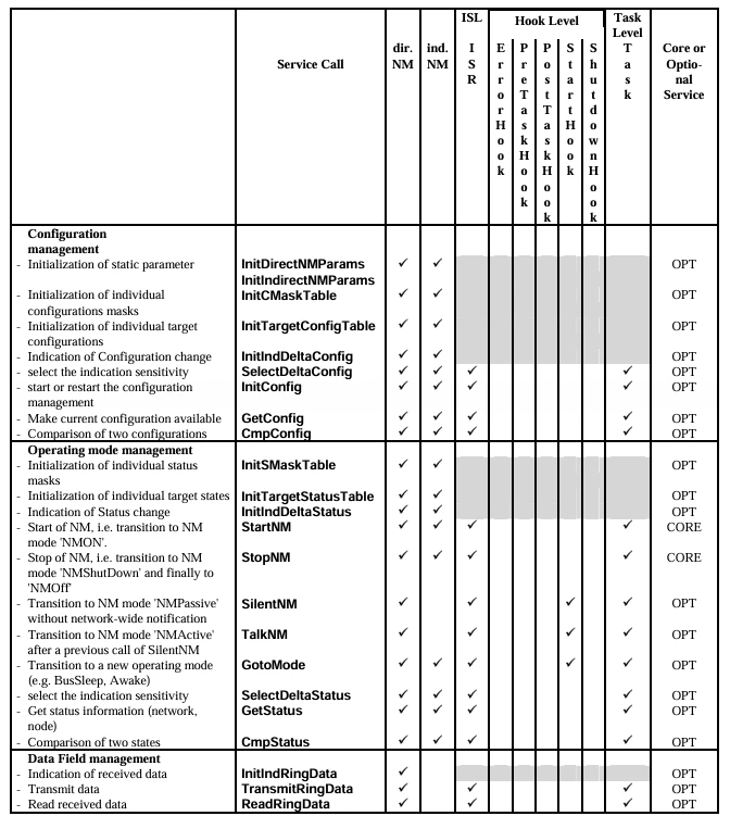
Therefore, the following services are provided:
• Initialization of ECU resources, e.g. network interface.
• Start-up of network
• Providing network configuration
• Management of different mechanisms for node monitoring
• Detecting, processing and signaling of operating states for network and
node
• Reading and setting of network- and node-specific parameters
• Coordination of global operation modes (e.g. network wide sleep mode)
• Support of diagnosis
1. Scope of the OSEK Network Management
Figure 1 interface and algorithms responsibility
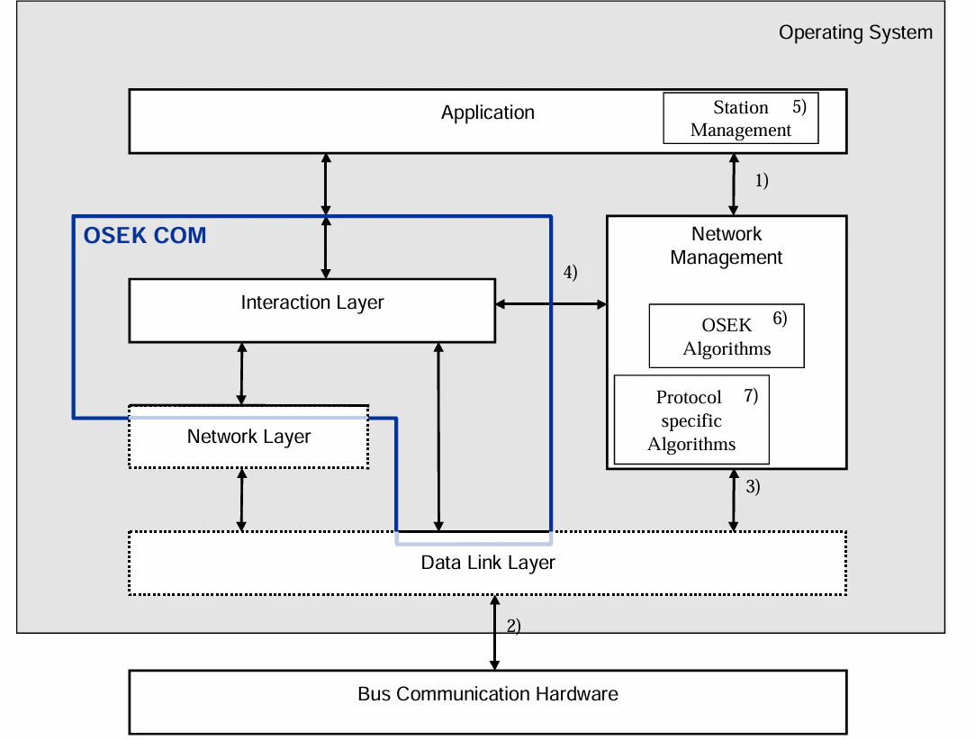
- API, fixed by OSEK
- several buses connected to one µController
- interface to DLL - COM specific, protocol specific
- interface to COM Interaction Layer
- station management (outside OSEK, see text below)
- OSEK algorithms
- protocol specific management algorithms
2. Direct Network Management
2.1. Concept
2.1.1. Node Monitoring
Figure 2 Infrastructure of the NM (logical ring), example with two buses
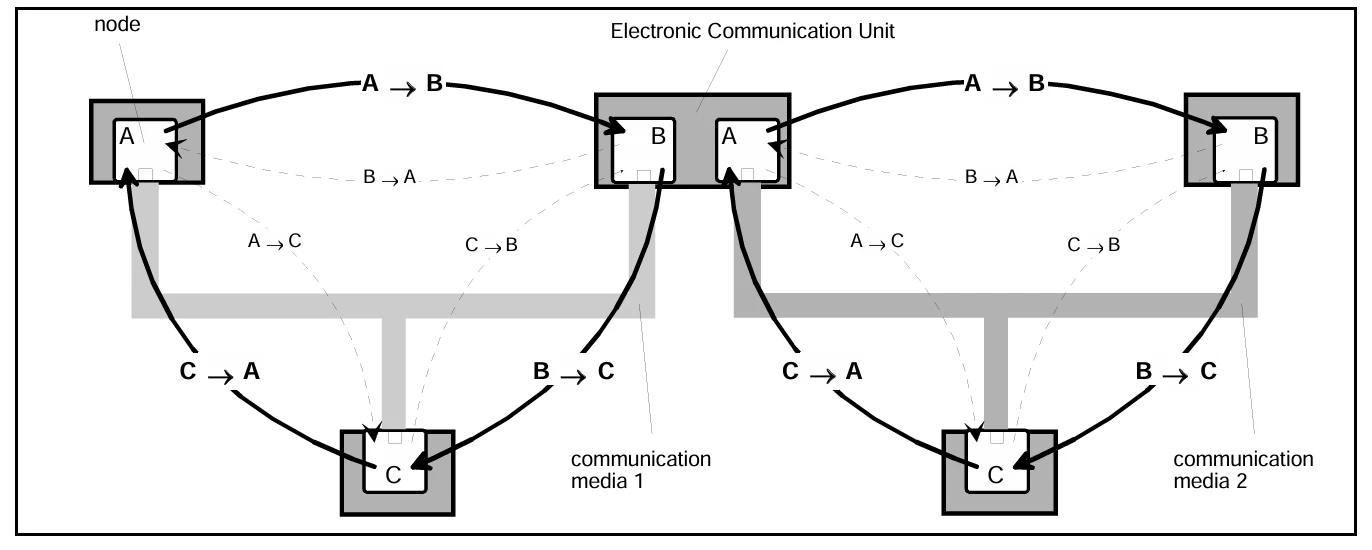
State of a node
Interpretation as transmitter related registration to the logical ring.
Interpretation as transmitter specific alive signal and
synchronization to initiate transmission of own NM
message according to the logical ring algorithm.
Interpretation as transmitter specific break down
A monitoring node is able to distinguish 2 states of a monitored node.
node present specific NM message received (alive or ring)
node absent specific NM message not received during time-out
A monitoring node is able to distinguish 2 states of itself.
present or not mute
specific NM message transmitted (alive or ring)
absent or mute
2.1.2. Addressing
Figure 3 Exemplary representation of encoding of a NM communication message onto a 
general protocol format.
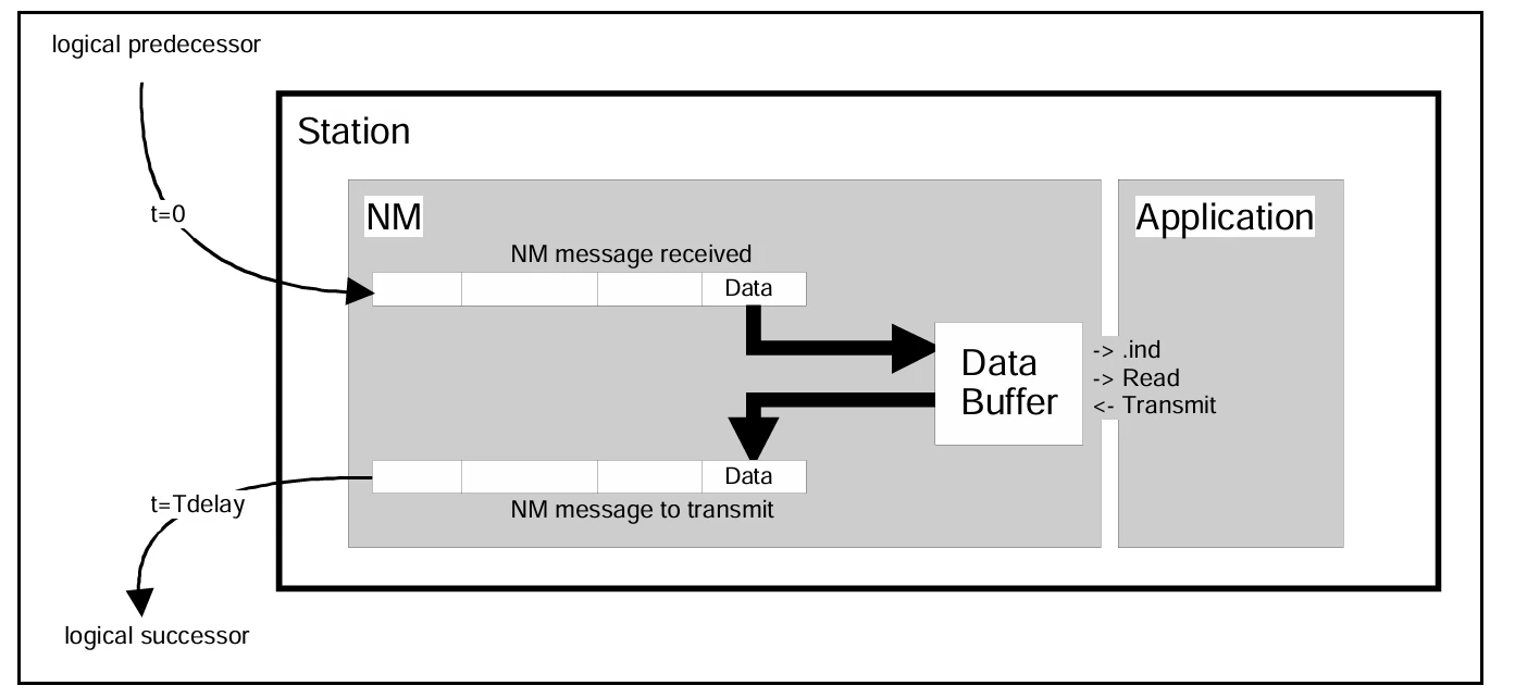
2.1.3. NM Infrastructure for Data Exchange
Figure 4 Mechanism to transfer application data via the logical ring
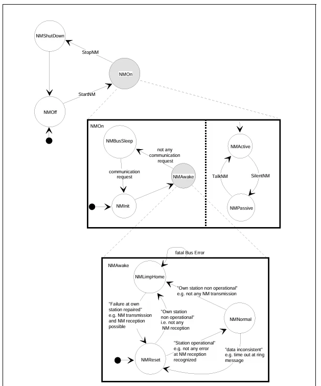
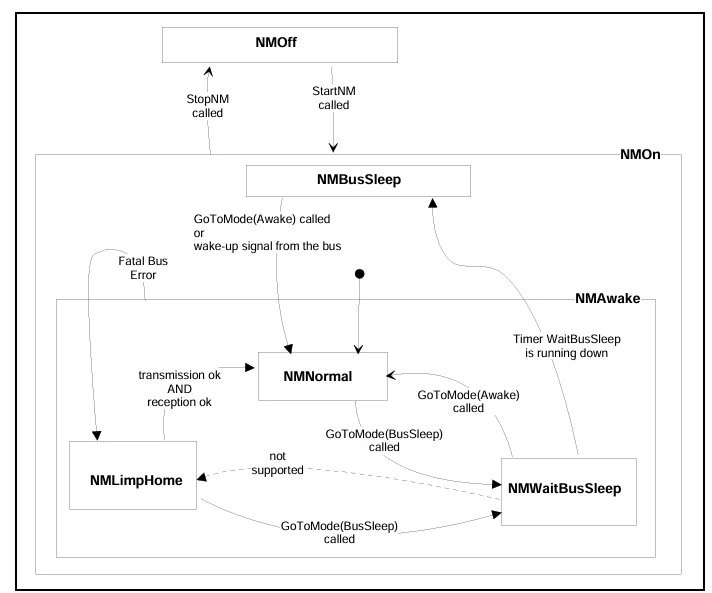
2.1.4. Standard Functionality
Figure 5 Simplified state transition diagram of the direct NM.
2.1.5. Configuration Management
2.1.6. Operating Modes
2.1.7. Network Error Detection and Treatment
2.1.8. Support of Diagnostic Application
2.2. Algorithms and Behavior
2.2.1. Communication of the Network Management System.
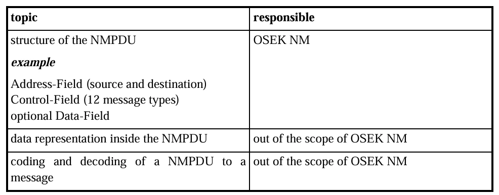
2.2.1.1. Network Management Protocol Data Unit
Table 1 NMPDU - the representation of the data is not fixed To guarantee the interoperability the data representation and the NMPDU encoding and decoding algorithms have to be fixed.
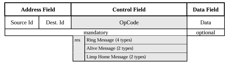
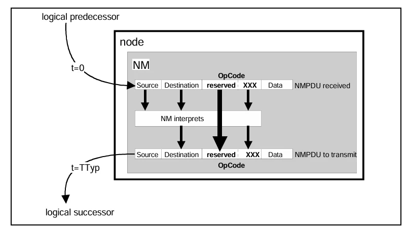
Figure 6 NM actions with the reserved area of the OpCode XXX encoding of NM message types
2.2.1.2. Addressing Mechanisms used by the Network Management
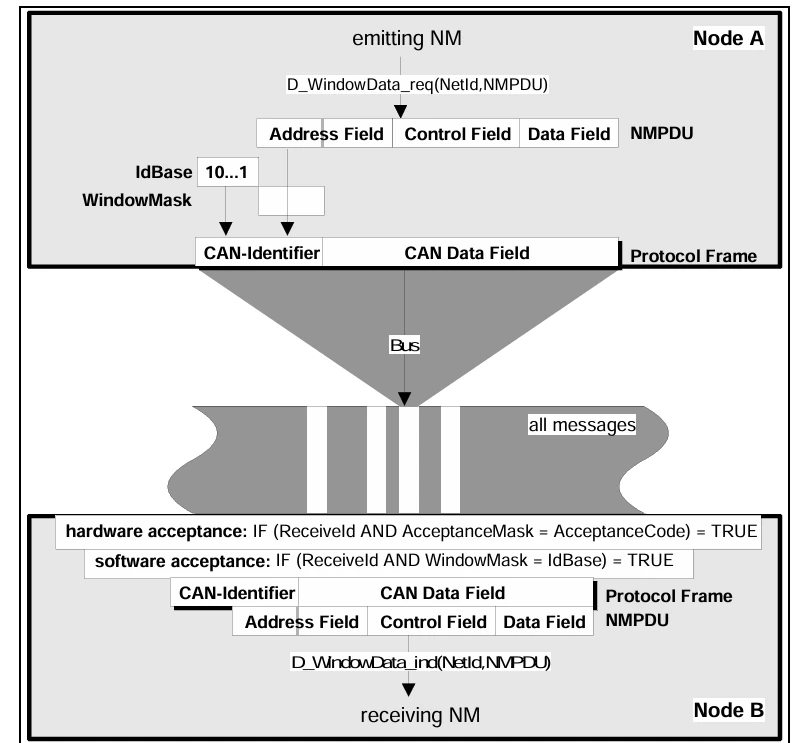
Figure 7 Encoding/decoding of the NMPDU to/from a message on the bus.

Figure 8 Transmission and reception of NM protocol data units (NMPDU).

Figure 9 CAN-Example for the transmission and reception mechanisms of a NMPDU
The CAN identifier consists of two parts:
- a fixed IdBase
- some bits of the address field, chosen by a mask
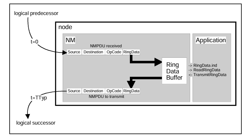
2.2.2. NM Infrastructure for Data Exchange
Figure 10 Handling of data exchange between NM and Application
2.2.3. Standard Tasks
2.2.3.1. Network Management Parameters
Table 2 NM parameters

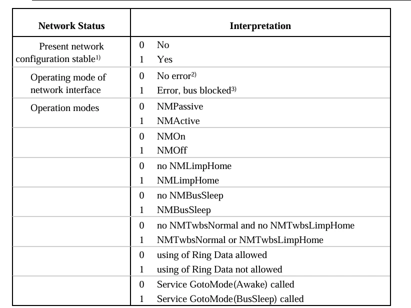
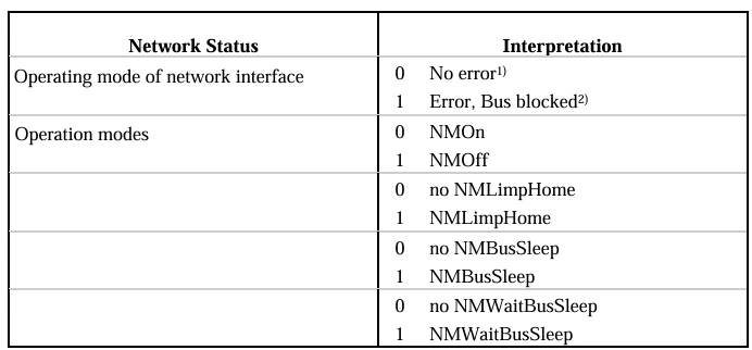
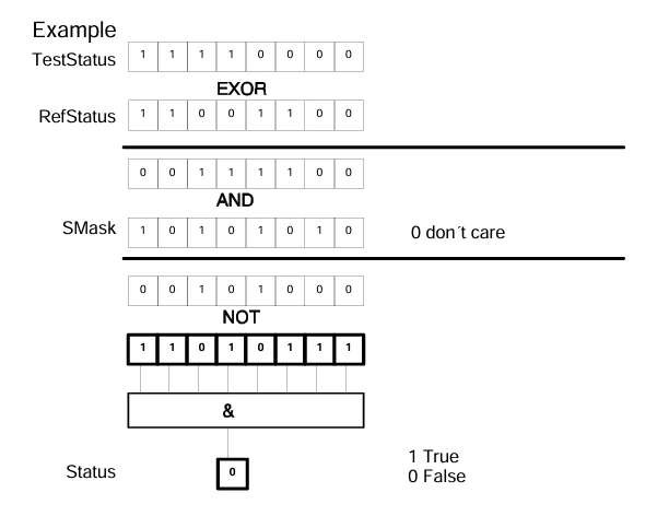
2.2.3.2. Network Status
Table 3 Service GotoMode(BusSleep) called Encoding of the network status.
- Configuration did not change during the last loop of the NM message in the logical ring
- Reception and transmission of NM messages successful
- e.g. CAN-busoff

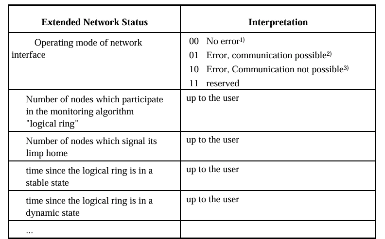
2.2.3.3. Extended Network Status
2.2.4. Configuration Management
2.2.4.1. Timing Reference
2.2.4.2. Monitoring Counter
2.2.4.3. State transition diagram
Figure 11 State transition diagram of the NM algorithms for initialization, start up and monitoring of a network (logical ring and limp home)
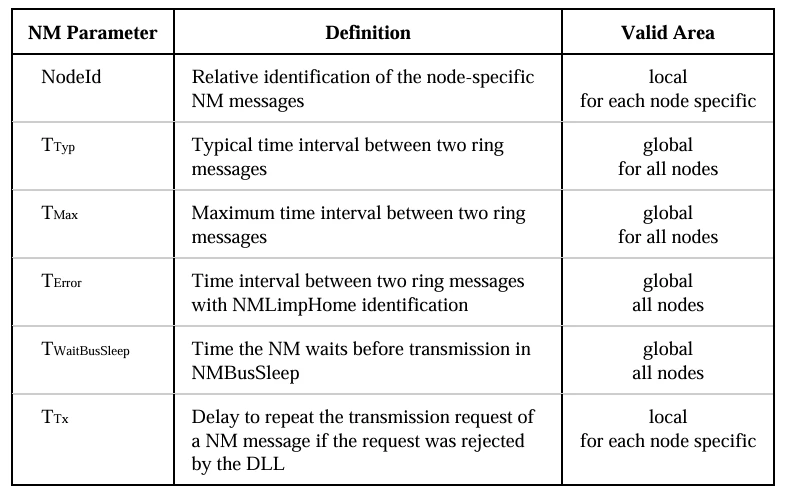
Figure 12 skipped in the logical ring

Figure 13 Actions during NMNormal in case a NM message is received "at a time"
####Figure 14 Regeneration principle of decentralized configuration management as a basis for NM communication in the logical ring
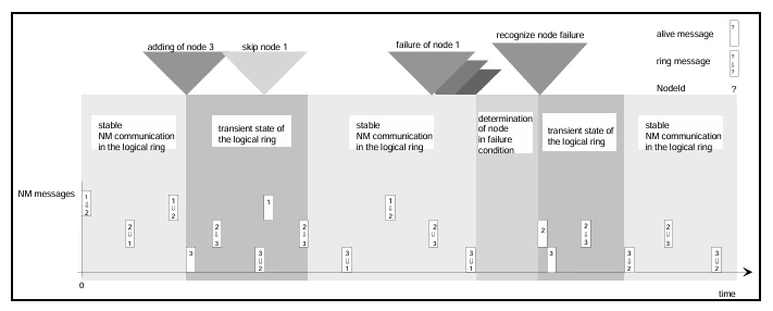
Figure 15 ring messages from the nodes i and k on an asynchronous bus
t1 The timer TTyp in node i has elapsed and the ring message of node i is
released for transmission. As the bus is busy, this ring message cannot be transferred.
t2 Node i receives the respective ring message from node k.
t3 The ring message of node i is transmitted to the bus.
t4 The ring message of node i was transmitted to the bus successfully.
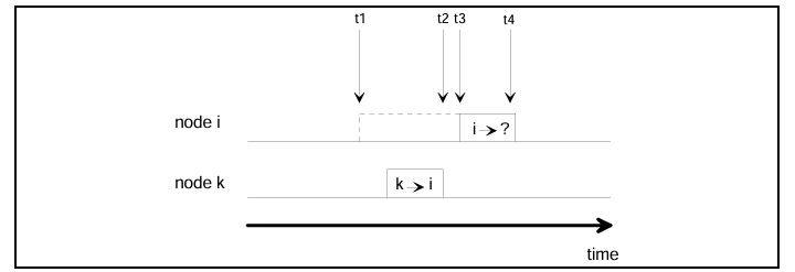
Table 5 Timer actions in NMNormal, during various bus actions.
- a duplicated ring is avoided (see text below)

Table 6 Main actions which are triggered by an expired timer in NMNormal.
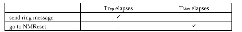
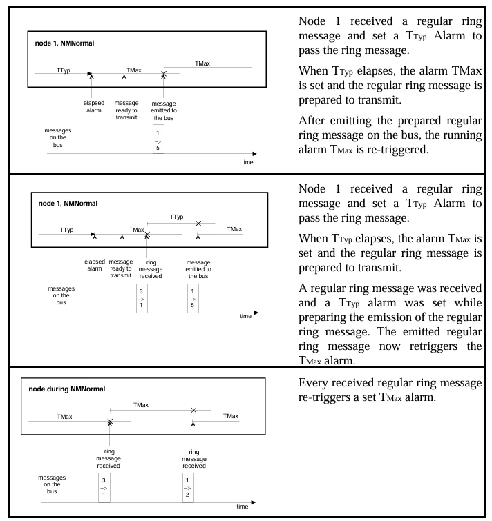
Figure 16 Examples for mechanisms to synchronize the NM alarms and their effects on the behavior of the NM
top Passing of a ring message during the fixed state of the logical ring.
middle Passing of a ring message during the dynamic state of the logical ring - mechanism to avoid two ring messages.
bottom Monitoring of ring messages during the fixed state of the logical ring.
2.2.5. Example: Skipped in the logical ring
Figure 17 temporary logical ring for test, whether the receiver node has been skipped or not
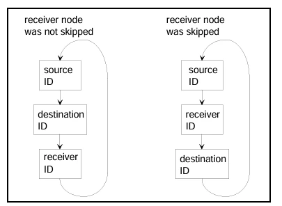
temporary logical ring for the test, whether the receiver node has been skipped or not
Source ID Transmitter of the ring message
Destination ID addressed node
Receiver ID Receiver of the ring message
Figure 18 IF-conditions for the test

IF-conditions for the test “Was a receiver node skipped by a ring message on the logical ring?”
S node identification of the source
R node identification of the receiver
D node identification of the destination
From two to three IF conditions are necessary
2.2.6. Example: Logical Successor
Figure 19 IF conditions to determine a logical successor
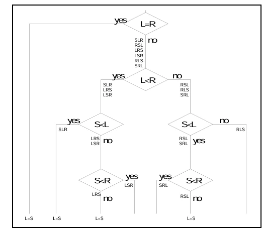
IF conditions to determine a logical successor
S node identification of the source
R node identification of the receiver
L node identification of the logical successor in the receiver node
From three to four IF conditions are necessary.
2.2.7. Operating Mode
2.2.7.1. NMActive - NMPassive
Figure 20 Toggling between NMActive and NMPassive
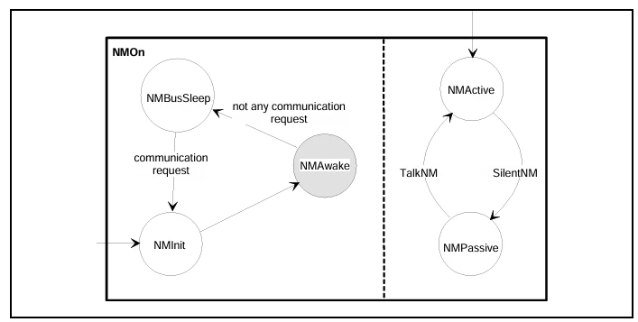
2.2.7.2. NMBusSleep - NMAwake
Table 7 Services to change between the states NMBusSleep and NMAwake.
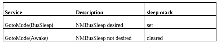
Figure 21 Algorithm of the transition: NMNormal <-> NMBusSleep
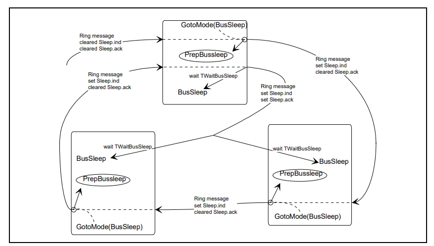
Note:
All nodes are ready to change over into NMBusSleep only if the signaling specified by InitIndDeltaStatus is carried out.
Up to that moment, application and NM must operate in its normal mode (i.e. NMNormal). The application still continues with its communication in the network, thus preventing error messages by the asynchronous transition of the nodes into NMBusSleep.
Figure 22 Algorithm for transition NMNormal <-> NMBusSleep

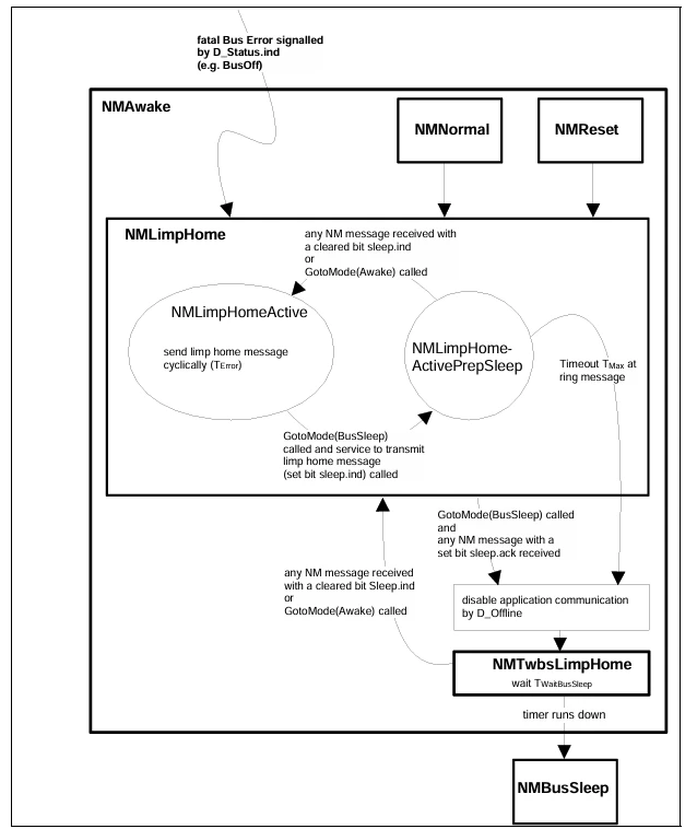
Figure 23 Algorithm for transition NMLimpHome <-> NMBusSleep
2.2.8. Fusion of Configuration Management and Operating Modes
2.2.8.1. State Diagrams
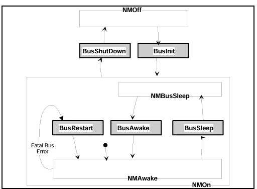
Figure 24 Simplified state transition diagram of the direct NM configuration management and operation modes are summarized

Figure 25 State transition diagram of NMInit
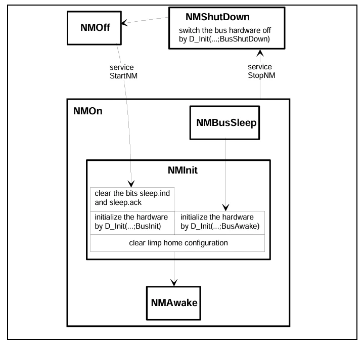
Figure 26 State transition diagram of NMBusSleep
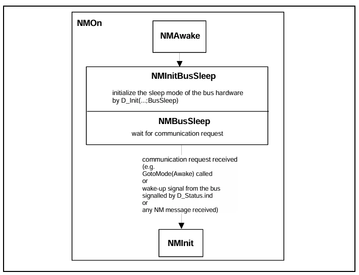
Figure 27 State transition diagram of NMReset
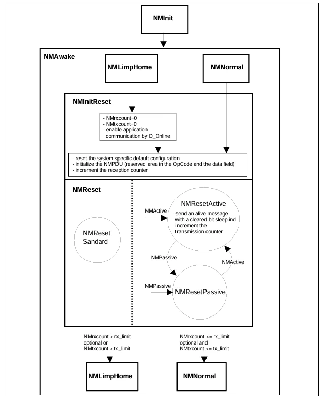
Figure 28 State transition diagram of NMNormal
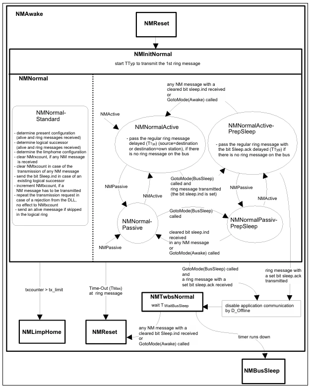
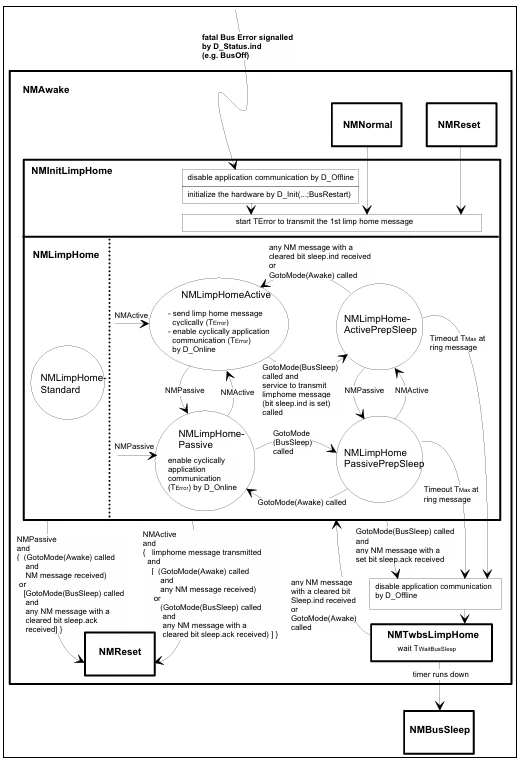
Figure 29 State transition diagram of NMLimpHome
2.2.8.2. SDL Diagrams
Figure 30 Start-up of the network
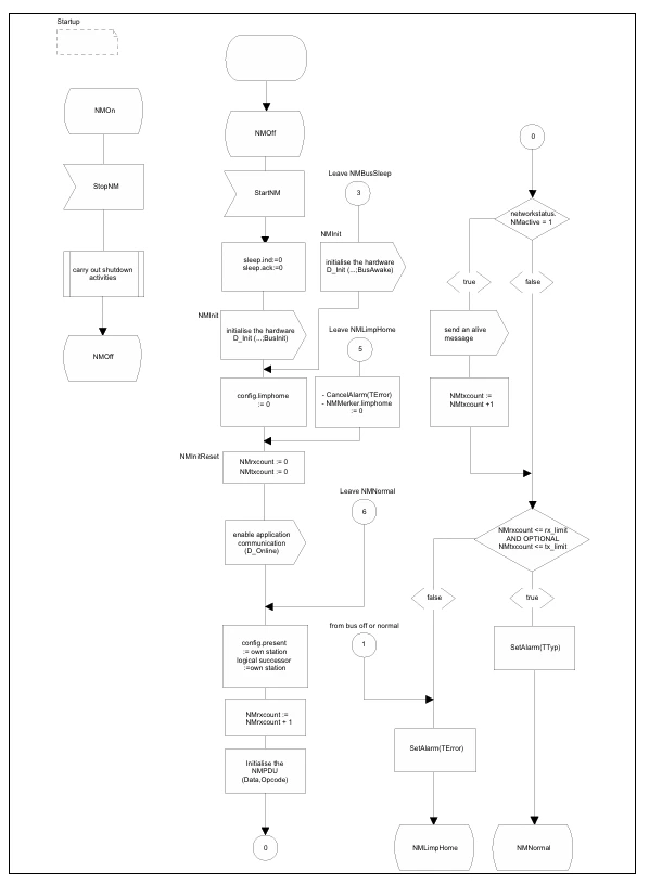
Figure 31 Transitions between NMActive and NMPassive, wake up from NMBusSleep, and bus off event.
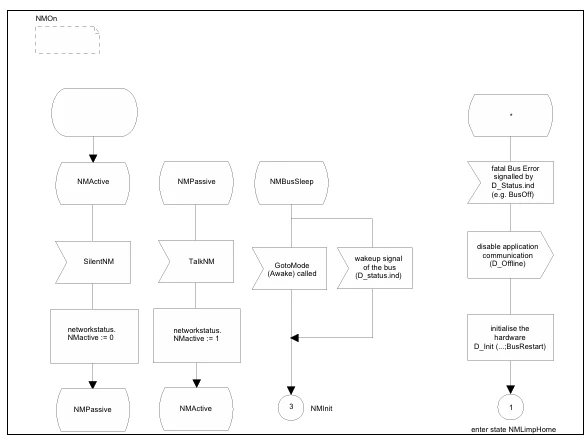
Figure 32 Actions during the state NMNormal and transitions to leave the state NMNorma

Figure 33 Actions during the state NMNormalPrepSleep and transitions to leave the state NMNormalPrepSleep
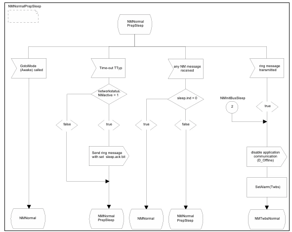
Figure 34 Transitions to leave state NMTwbsNormal
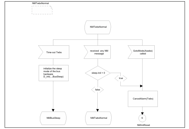
Figure 35 Actions during the state NMLimpHome and transitions to leave the state NMLimpHome

Figure 36 NMLimpHomePrepSleep
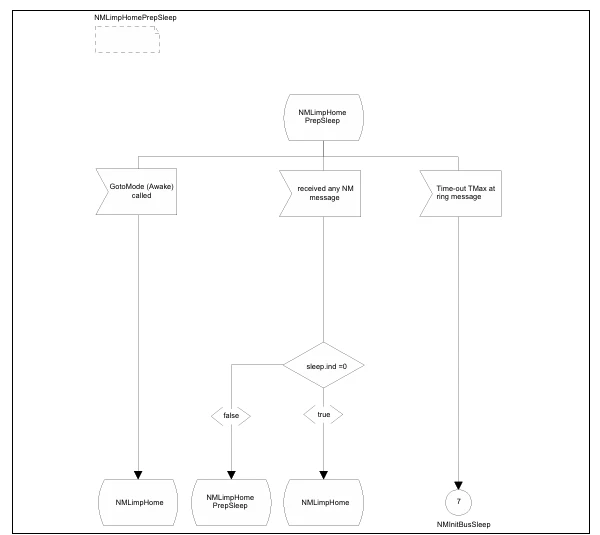
Figure 37 Transmissions to leave the state NMTwbsLimpHome
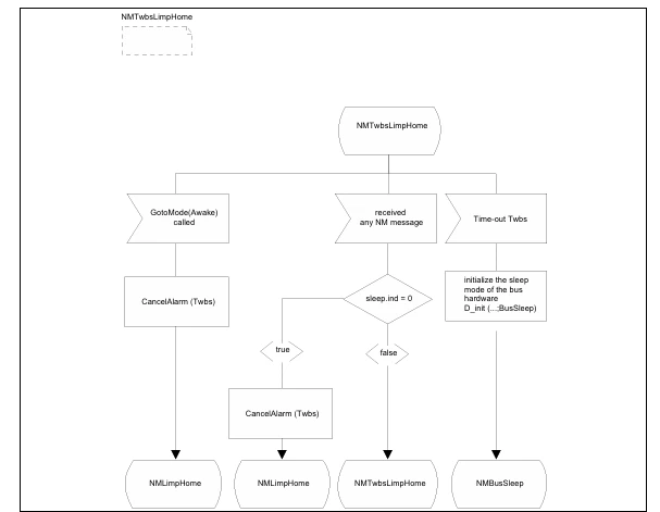
Figure 38 Actions during NMNormalStandard
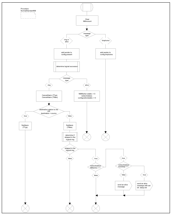
Figure 39 DLL transmit rejection and GotoMode(Awake/BusSleep)
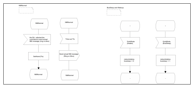
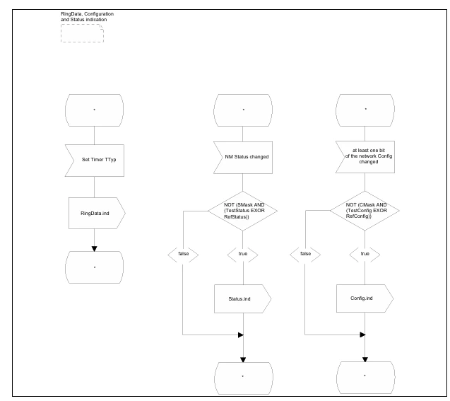
Figure 40 Indication of ring date, configuration and network status
2.2.9. Alarms inside the Network Management
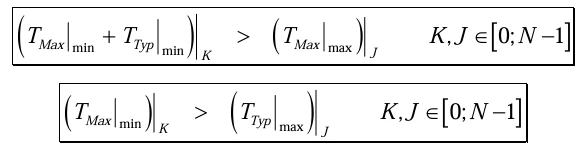
2.2.9.1. Rules to design the alarms TTyp and TMax
Figure 41 TTyp and TMax
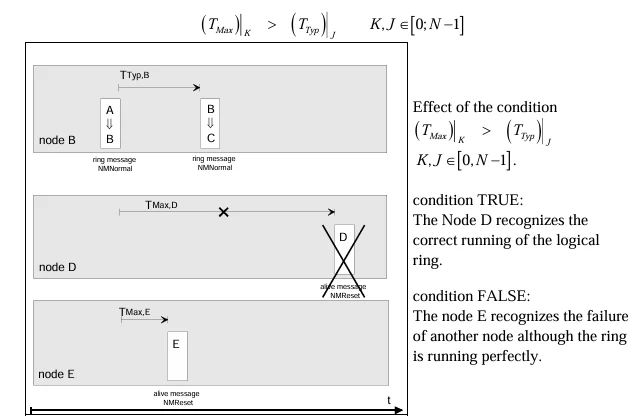
Figure 42
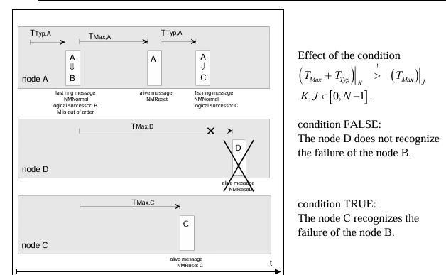
Each of this alarms has to be provided with a tolerance (...⏐min and ...⏐max) for every node. Inside a network all nodes must meet both requirements:
2.2.9.2. Rules to design the alarm TError
2.2.9.3. Rules to design the alarm TWaitBusSleep
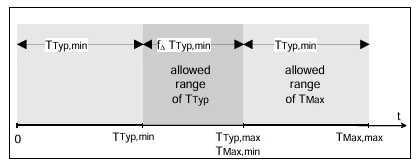
2.2.9.4. Design of a system
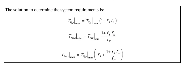
2.2.9.4.1. Worst Case
Figure 43 Worst case system design of the alarms inside the NM.
2.0.1.4.2. Example
Every node has to guarantee that their alarms remain inside the fixed limits.

3. Indirect Network Management
3.1. Concept
3.1.1. Node Monitoring
3.1.1.1. Node states
3.1.1.2. Extended Node states
3.1.2. Configuration-Management
3.1.2.1. Configuration
3.1.2.2. Extended Configuration
3.1.3. Standard Task
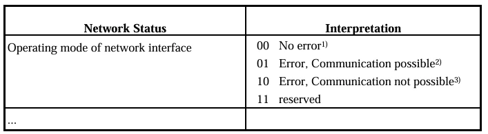
3.1.3.1. Network status
Table 8 Encoding of the network status
- Reception and transmission of application messages successful
- e.g. CAN-busoff
3.1.3.2. Extended network status
Table 9 Example of encoding of the extended network status.
- Reception and transmission of application messages successful
- communication via one wire
- e.g. CAN-busoff for a "long" time
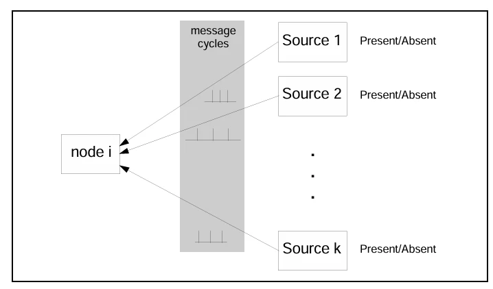
3.1.4. Monitoring Mechanisms
Figure 44 Reception monitoring
3.1.5. Monitoring time-outs
3.1.5.1. One global time-out
3.1.5.2. One monitoring time-out per message
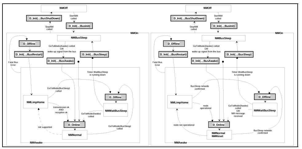
3.1.5.3. Internal Network Management States
Figure 45 Simplified state transition diagram of the indirect NM.
3.1.6. Operating Modes
3.2. Algorithms and behavior
3.2.1. Configuration Management
3.2.1.1. Counter management
Figure 46 Extended configuration illustrated at node k.
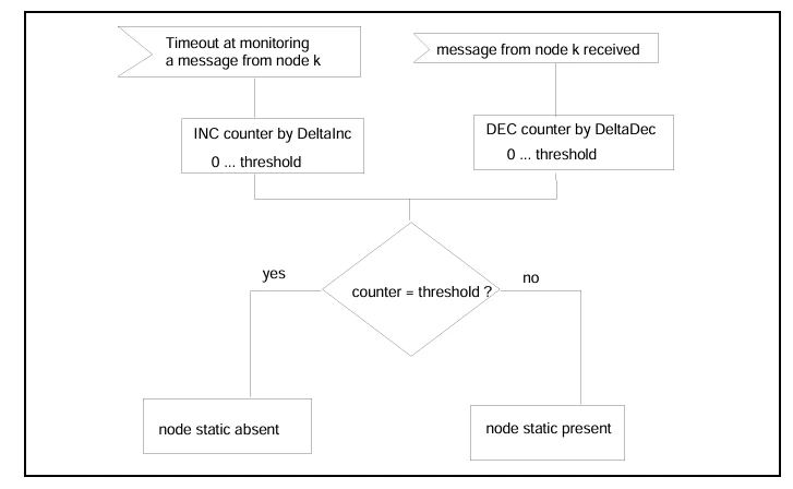
Figure 47 Extended configuration illustrated at node k in the case of a very transient state of the node - the state "static absent" will not be reached.
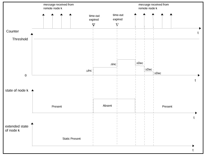
Figure 48 Extended configuration illustrated at node k in the case of a permanent state of the node.
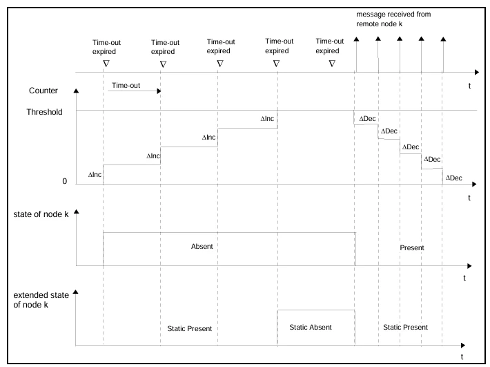
Figure 49 Extended configuration illustrated at node k in case of a repetitive state of the node.

3.2.2. Operating Mode
3.2.2.1. User Guide to handle BusSleep
Table 10 Example of the application behavior to handle NMAwake and NMBusSleep according to a master slave approach.

3.2.3. State Machine in SDL
3.2.3.1. SDL Model for one global time-out TOB
Figure 50 Handling of the services StartNM and StopNM
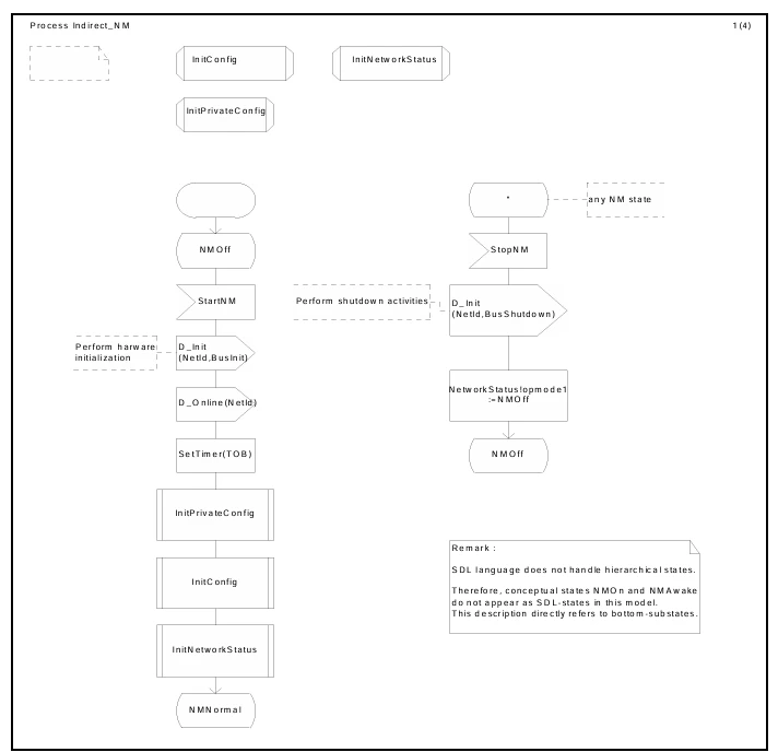
Figure 51 Handling of the events "TOB" and "message received" during state NMNormal
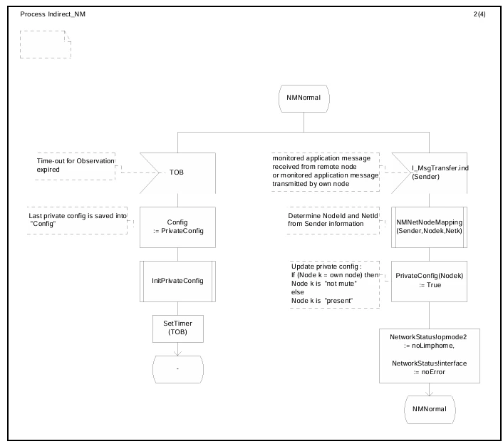
Figure 52 Handling of the events "TOB" and "message received" during NMLimpHome
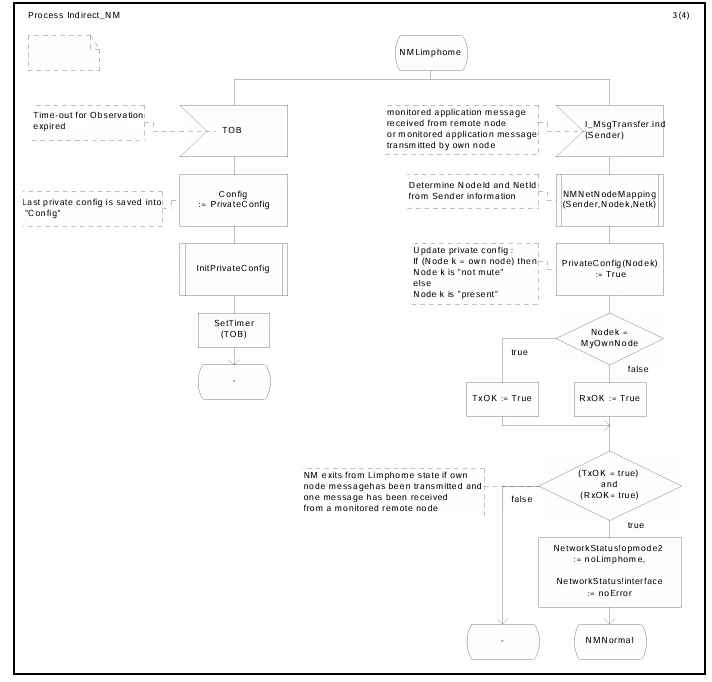
Figure 53 Handling of a fatal bus error
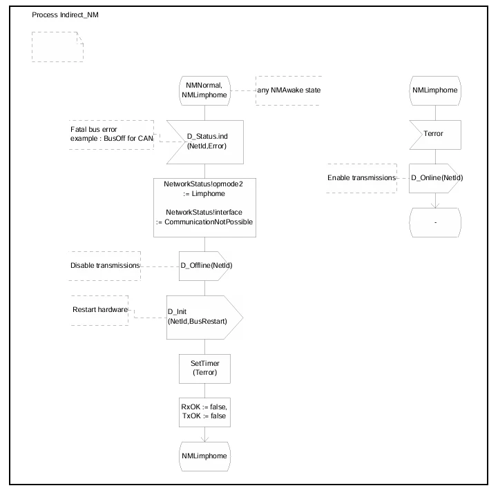
Figure 54 Initialization of the configuration
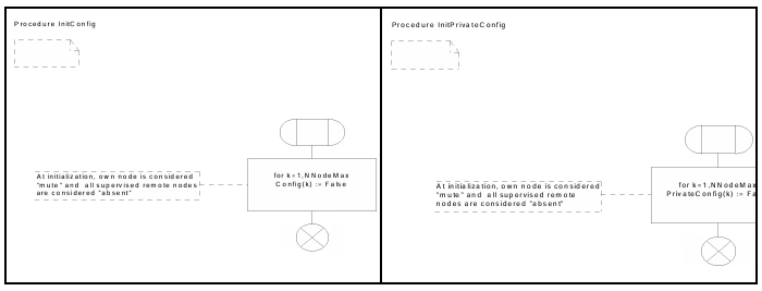
Figure 55 Initialization of the NM status
3.2.3.2. SDL Model for one monitoring time-out per message
Figure 56 Handling of the services StartNM, StopNM and InitConfig

Figure 57 Handling of the events "timeout for message" and "message received" during state NMNormal
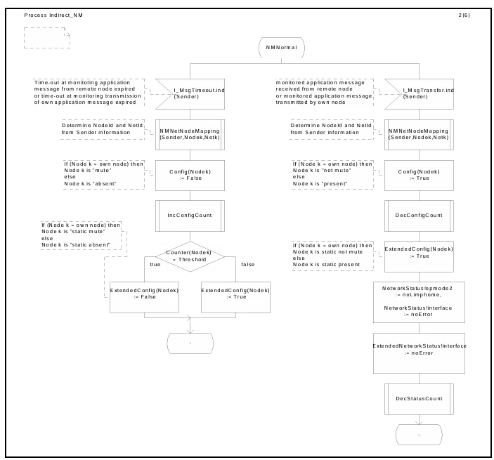
Figure 58 Handling of the events "timeout for message" and "message received" during state NMLimpHome
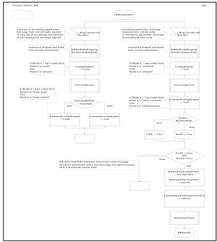
Figure 59 Handling of a fatal bus error
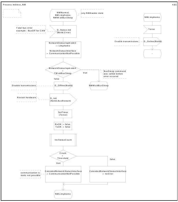
Figure 60 Handle the transition to the state NMBusSleep
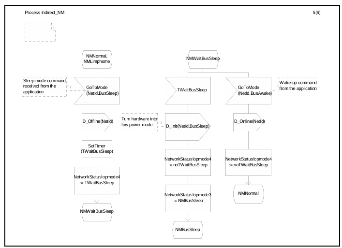
Figure 61 Handle the transition from NMBusSleep into NMNormal
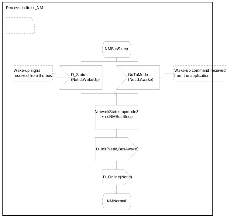
Figure 62 Initialization of the configuration
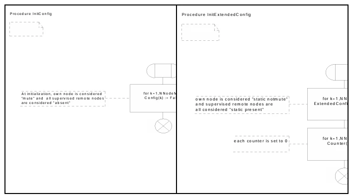
Figure 63 Initialization of the NM status
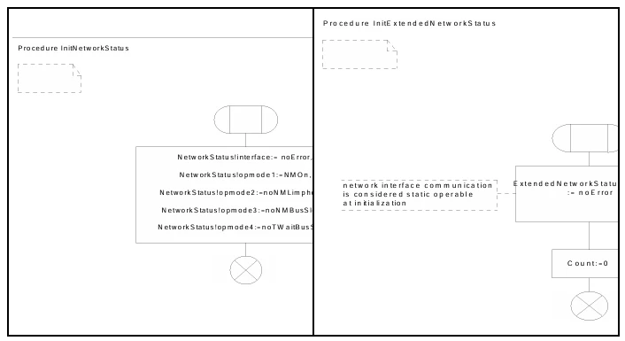
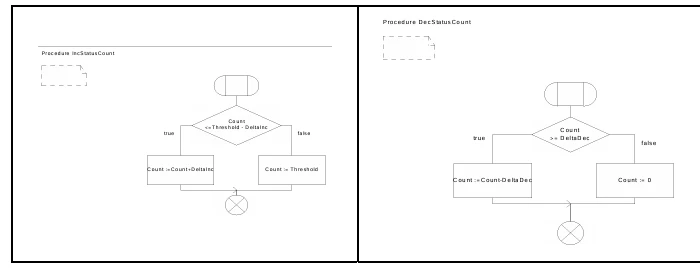
Figure 64 Decrement and increment procedures for the extended configuration

Figure 65 Decrement and increment procedures for the extended network status
4. System generation and API
4.1. Overview
Figure 66 Syntax of a NM service.
Example: GetConfig

Table 11 Breakdown of NM API-services into core services and optional services. Call to the NM service is allowed in this level (Interrupt level ISL, Hook level and Task level)
4.2. Conventions for Service Description
4.2.1. System Generation
4.2.2. Type of Calls
4.2.3. Error Characteristics
4.2.4. Structure of the Description
4.2.4.1. System Generation Support
4.2.4.2. Service Descriptions
4.3. General Data Types
Table 12 General data types

4.4. Common services
4.4.1. Standard Functionality
4.4.1.1. System Generation Support
Figure 67 Routines to initialize, restart and shut down the bus hardware.
The routines depend on the given hardware design and on the behavior of the NM which the application requires.
4.4.2. Configuration Management
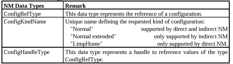
4.4.2.1. Data Types
Table 13 Special data types of the configuration management
4.4.2.2 System Generation Support
4.4.2.3. Services

4.4.3. Operating Modes and Operating Mode Management
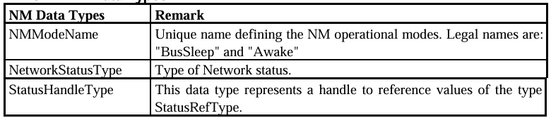
4.4.3.1. Data Types
Table 14 Special data types of the operating mode management
4.4.3.2. System Generation Support
4.4.3.3. Services
4.5. Services for direct NM
4.5.1. Standard Functionality
4.5.2. Operating Modes and Operating Mode Management
4.5.3. Data Field Management
4.5.3.1. Data Types
Table 15 Special data types of the data field management

4.6. Services for indirect NM.106
4.6.1. Standard functionality.106
4.6.1.1. System Generation Support
4.6.2. Configuration Mangement106
4.6.2.1. System Generation Support
5. Impacts upon OS, COM and the data link layer.107
5.1. Error Codes.107
5.2. Common impacts108
5.2.1. Requirements of the data link layer108
Figure 68 Using of DLL services by the NM, left indirect NM, right direct NM
5.2.2. Requirements of OSEK Operating System (OSEK OS).110
5.3. Impacts from direct NM111
5.3.1. Interface to the data link layer111
Table 16 NMPDU - responsible
5.4. Impacts from indirect NM112
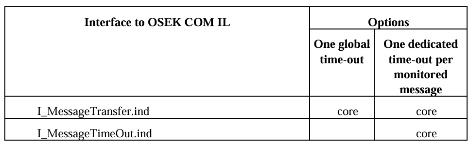
5.4.1. Interface to OSEK Communication (OSEK COM)112
Table 17 Interface of indirect OSEK NM with OSEK IL
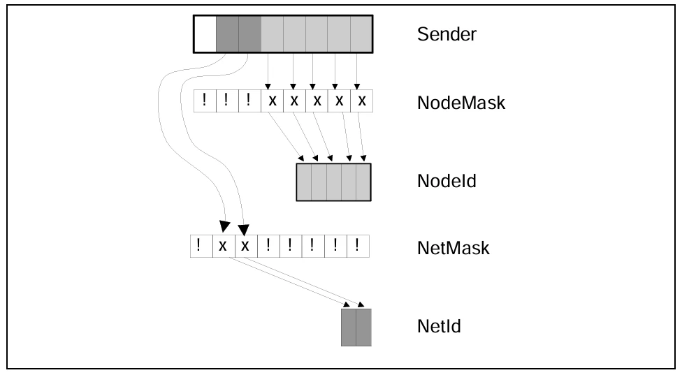
5.0.0.1. Mapping NodeId, NetId ⇔ Sender
Figure 69 Encoding and decoding of sender to a NodeId and a NetId by using a mechanism with a Mask. (x = don't care, take Message bit; ! = do not take this bit)
6. History.115
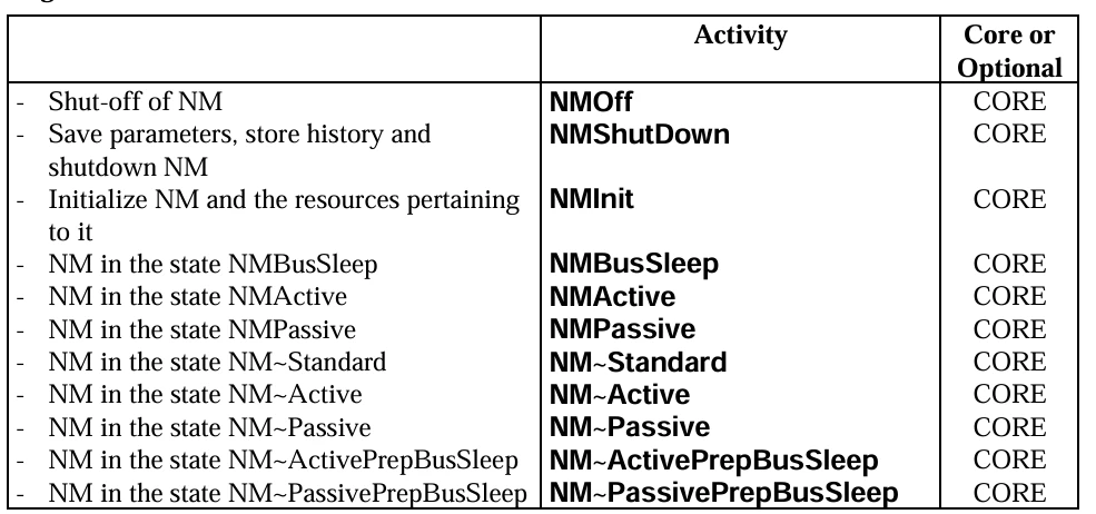
#7. Implementation proposal (direct NM)116
7.0.1. Overview of Internal Activities116
Figure 70 Syntax of the names of internal NM services.
Example: NMShutDown
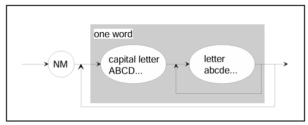
Table 18 Breakdown of internal NM activities into core services and optional services. ~ Reset, Normal or LimpHome

Figure 71 Simplified state transition diagram of the direct NM.
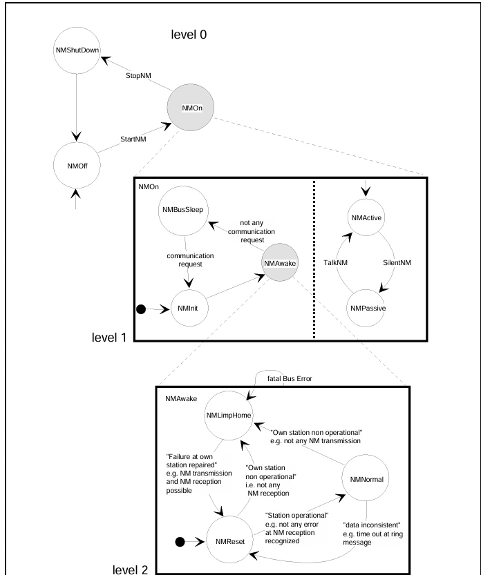
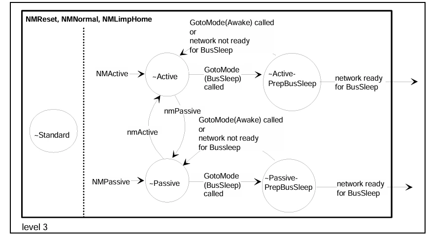
Figure 72 NM internal states "NMNormal" or "NMReset" or "NMLimpHome
7.0.2. Specification of Internal Activities.119
7.0.3. NMPDU
7.0.3.1. OpCode
Figure 73 Implementation of NMPDU

7.0.3.2. Encoding and decoding
Table 19 NMPDU The 1st 5 bits of the OpCode are reserved for future extensions. They should be initialized to logical zero. The data field should be initialized to logical zero
7.0.3.2.1. Addressing Mechanisms
Figure 74 Encoding and decoding of the NMPDU to a message by using the window
mechanism with IdBase and WindowMask.
(x = don't care, take NMPDU bit; ! = take original bit of IdBase)
7.0.3.2.2. Coherent Allocation of NM message Headers
Table 20 Selection of message headers and NodeNumbers
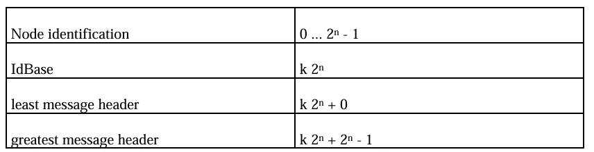
Figure 75 Structure of NM message in case of CAN (6 Byte Data Field).
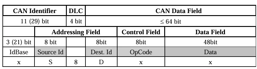
Figure 76 Structure of NM message in case of CAN (without Data Field).
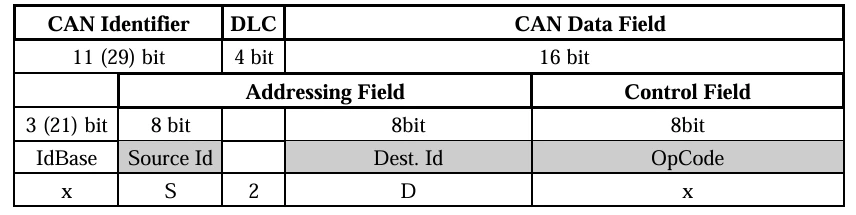
Figure 77 Example of the mapping of the NMPDU to a NM message based on CAN comparable to the DaimlerChrysler encoding, x = reserved

7.0.3.2.3. Non-coherent Allocation of NM message Headers
7.0.3.2.4. Node Identifications
Table 21 Determination of node identifications using the example n=8
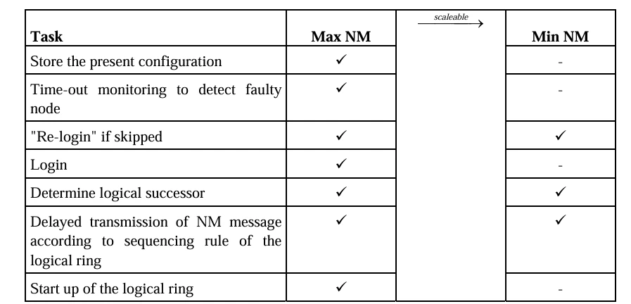
7.0.4. Scalability
Table 22 Functionality of the configuration algorithms of Max NM and Min NM
7.1. Implementation proposal (indirect NM)
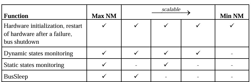
7.1.1. Scalability
Table 23 - Example of functionality for different NM types
7.1.2. Implementation hints
7.1.2.1. Choice one global time-out / one monitoring time-out per message
7.1.2.2. Configuration of extended states detection algorithm
Figure 78 Extended state example one

Table 24 Calculation of DeltaInc and DeltaDec according example one TimeOutk: monitoring time-out for node k
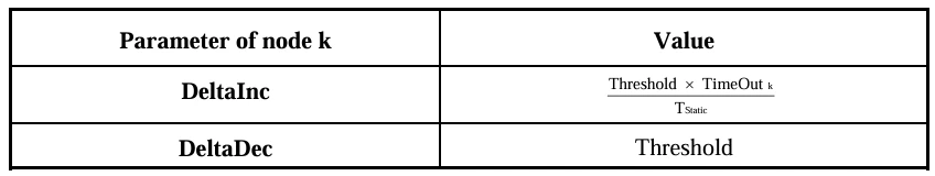
Figure 79 Extended state example two
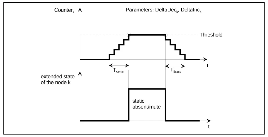
Table 25 Calculation of DeltaInc and DeltaDec according example one TimeOutk: monitoring time-out for node k, Tk: period of the supervised message received from node k

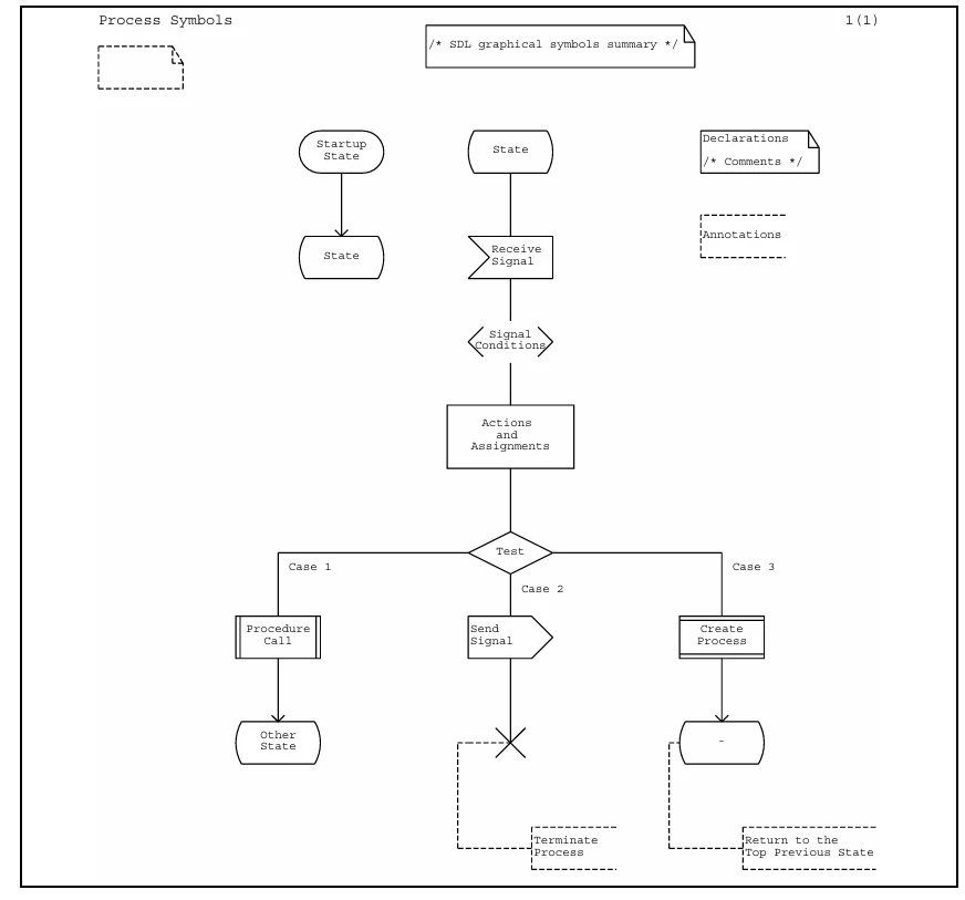
7.1.3. Summary of SDL state diagram graphical notation
Figure 80 Summary of SDL state diagram graphical notation
7.2. Outlook
8. Index
CmpConfig 96
CmpStatus 100
ConfigHandleType 91
ConfigKindName 91
ConfigRefType 91
EventMaskType 89
GetConfig 95
GetStatus 99
GotoMode 98
InitCMaskTable 91
InitConfig 94
InitDirectNMParams 101, 105
InitExtNodeMonitoring 106
InitIndDeltaConfig 92
InitIndDeltaStatus 94
InitIndRingData 103
InitNMScaling 90
InitNMType 89
InitSMaskTable 93
InitTargetConfigTable 92
InitTargetStatusTable 93
NetIdType 89
NetworkStatusType 97
NMActive 118
NMBusSleep 118
NMInit 118
NMLimpHomeActive 121
NMLimpHomeActivePrepBusSleep 119
NMLimpHomePassive 121
NMLimpHomePassivePrepBusSleep 120
NMLimpHomeStandard 122
NMModeName 97
NMNormalActive 120
NMNormalActivePrepBusSleep 119
NMNormalPassive 121
NMNormalPassivePrepBusSleep 120
NMNormalStandard 122
NMOff 117
NMPassive 118
NMResetActive 121
NMResetActivePrepBusSleep 119
NMResetPassive 121
NMResetPassivePrepBusSleep 120
NMResetStandard 122
NMShutDown 117
NodeIdType 89
ReadRingData 104
RingDataType 103
RoutineRefType 89
SelectDeltaConfig 97
SelectDeltaStatus 101
SelectHWRoutines 90
SignallingMode 89
SilentNM 102
StartNM 98
StatusHandleType 97
StatusType 89
StopNM 98
TalkNM 102
TaskRefType 89
TickType 89
TransmitRingData 104
memo
must
Introduction p.3
At a basic configuration stage, NM implementations complying with OSEK specifications must be implemented in all networked nodes.
4 Glossary (INFORMATIVE)
1:1 Connection
logical communication channel between a transmitter and a receiver. A message is sent by exactly
one transmitter and is received by exactly one receiver
1:N Connection
logical communication channel between a transmitter and N receivers. A message is sent by exactly
one transmitter and is received by N receivers
Acceptance Filtering
mechanism which decides whether each received protocol frame is to be taken into account by the
local Node or ignored
Activate
state transition of a task from suspended to ready. The transition is achieved by a system service
Actual Configuration
set of all operable nodes (see operability of a node ) to which communication access is possible
Address-related Communication
special kind of communication between nodes using node addresses (see node addressing). Each
address-related communication message contains certain data and - either explicitly or implicitly - the
node address of the transmitter and the receiver. The communication of the network management is
completely based on address-related communication
Alarm
alarm is an association between a counter and a task, event or callback. An alarm expires when a
predefined counter value is reached. The expiry value can be defined relative to the current counter
value or can be an absolute value. Alarms can be defined to be either single-shot or cyclic. An alarm
is statically assigned at system generation time to: one counter and a task, event or alarm callback
routine
Alarm callback
alarm callback routine is a short function provided by the application that gets called when the alarm
expires but before any task is activated or event set
Alarm Management
alarm management is based on the counter concept. It lets the user link alarm callbacks, task
activation or event setting to counter values. The link is done by use of alarms
Alive Message
dedicated NM message. An alive message is used to announce an initialised and operable node (see
operability of a node ) for integration in the actual configuration
API
Abbreviation of "Application Program Interface", the description of the application's interface to the
operating system, communications and network management functions
Application errors
error where the operating system can not execute the requested service correctly, but assumes the
correctness of its internal data. In this case, centralised error treatment is called
Arbitration
mechanism which guarantees that a simultaneous access made by multiple stations results in
contention where one frame will survive uncorrupted
Basic Conformance Class
conformance Class of the OSEK operating system in which only Basic Tasks are admitted. Two basic
conformance classes are distinguished: BCC1 and BCC2
© by OSEK - 12 -
OSEK/VDX BD 1.4.2
OSEK/VDX
Binding Specification
Basic Task
task that has a defined beginning and a defined end. Basic tasks only release the processor if they are
being terminated, the operating system is executing a higher-priority task or an interrupt occurs. A
Basic Task can only enter the task states suspended, ready and running. It is not possible for a Basic
Task to wait for an event
BCC
abbreviation of "Basic Conformance Class"
Broadcast
special case of multicast, whereby a single message is addressed to all nodes simultaneously
BNF
abbreviation of "Backus-Naur Form"
BT
abbreviation of "Basic Task"
BusOff
node is in the BusOff state when it is switched off from the bus. In the BusOff state a node can neither
send nor receive any protocol frames
CALLOUT
Callouts provide a general mechanism to customise and enhance the behaviour of the Interaction
Layer. Callouts are configured statically, are invoked in response to the passage of a message or I
PDU and cannot be changed at run-time. The prototype for a callout allows it to return a value
CAN
abbreviation of "Controller Area Network". A protocol originally defined for use as a communication
network for control application in vehicles
CC
abbreviation of "Conformance Class"
CCC
abbreviation of “Communication Conformance Class”
Certification
purpose of certification is to determine whether an implementation is consistent with a given reference
model. The scope of this reference model has to be settled according to the objectives of the
OSEK/VDX project. All constraints necessary to fulfil these objectives must be incorporated in the
reference model
COM
abbreviation of "Communication"
COM-callback
A COM-callback routine is a short function provided by the application which can be called by the
Interaction Layer as a notification mechanism (class 1). No parameters are passed to a COM-callback
routine and it does not have a return value. A COM-callback routine runs either on interrupt level or on
task level
Communication Layer
set of all entities and elements which constitute a communication layer based on the ISO/OSI
Reference Model (ISO 7498)
OSEK/VDX BD 1.4.2
© by OSEK
13
Configurability
ability to set the parameters of a system in terms of static values (e.g. number of tasks, RAM size for
stack, size of message buffer, etc.)
Confirmation
service primitive defined in the ISO/OSI Reference model (ISO 7498). With the 'confirmation' service
primitive a service provider informs a service user about the result of a preceding service request of
the service user
Conformance Class
in each module (operating system, communication, network management) a pool of services is
provided, each being divided into a number of subsets. Applications can choose to use different
subsets of the services in order to reduce demands on the CPU and memory. These subsets are
upwardly compatible and are described as conformance classes
Constructional Element
generic term for all definition and declaration services for system objects
Counter
counters are system objects that register recurring events, e.g. time, angle. A counter is represented
by a count and some counter-specific constants
CPU
abbreviation of "Central Processing Unit"
Critical Section
sequence of instructions where mutual exclusion must be ensured. Such a section is called 'critical'
because shared data is modified within it
Data Consistency
data consistency means that the content of a given message correlates unambiguously to the
operation performed onto the message by the application. This means that no unforeseen sequence
of operations may alter the content of a message hence rendering a message inconsistent with
respect to its allowed and expected value
Data Link Layer
communication layer which provides services for the transfer of I-PDUs. The data link layer consists of
the communication hardware and the communication driver software
Deadlock
state in which tasks block one another so that further processing of the tasks concerned is no longer
possible. A deadlock between two tasks occurs, e.g. if both tasks wait for the reception of a message
which is to be sent by the other task before sending its own message
Direct Node Monitoring
active monitoring of a node by another node in the network. For this purpose the monitored node
sends a NM message according to a dedicated and uniform algorithm. For the network-wide
synchronisation of NM messages a logical ring is used
Deadline Monitoring
in deadline monitoring the application is informed via the notification mechanism if: a message is not
received from another node within a specified interval, or if a request to send an I-PDU is not
completed by the DLL within a specified interval
DLL
abbreviation of "Data Link Layer"
ECC
abbreviation of "Extended Conformance Class"
ECU
abbreviation of "Electronic Control Unit" (see station)
© by OSEK - 14 -
OSEK/VDX BD 1.4.2
EPROM
OSEK/VDX
abbreviation of "Erasable Programmable Read Only Memory"
Error Handling
Binding Specification
error service is provided to handle errors detected by the operating system. Its basic framework is
predefined and has to be completed by the user. This gives the user a choice of efficient centralised or
decentralised error handling
Error Hook
the error hook routine (ErrorHook) is called if a system service returns a StatusType value not equal to
E_OK. ErrorHook is also called if an error is detected during task activation or event setting
ET
abbreviation of "Extended Task"
Event
events are a method of task synchronisation. Extended tasks may suspend their execution without
terminating by waiting for events. The task continues when an appropriate event is set. Basic tasks
may not use events
Event Mechanism
means of task synchronisation by using events
Extended Conformance Class
conformance Class of the OSEK operating system in which Basic and Extended Tasks are permitted.
Two extended conformance classes are distinguished: ECC1, ECC2
Extended Task
extended tasks are distinguished from Basic Tasks by being allowed to use additional operating
system services which may result in a waiting state. An Extended Task can enter the task states
suspended, ready, running, and waiting
Fatal Error
error where the operating system can no longer assume correctness of its internal data. In this case
the operating system calls the centralised system shutdown
FIFO
abbreviation of "First In First Out"
Frame
data unit according to the data link protocol specifying the arrangement and meaning of bits or bit
fields in the sequence of transfer across the transfer medium (see data link message)
Full-preemptive Scheduling
full preemptive scheduling means that a task which is presently running may be rescheduled at any
instruction by the occurrence of trigger conditions pre-set by the operating system. Full-preemptive
scheduling will put the running task into the ready state as soon as a higher-priority task has become
ready. The preemptee's context is saved so that it can be continued at the location where it was
preempted2.54
Group Addressing
addressing of several receiver nodes in a single address-related NM message (see address-related
communication). Group addressing is implemented by using multicast connections
the message objects are identified by a local (Node-wide) reference named handle. The handle is
attached to both a logical and physical address
OSEK/VDX BD 1.4.2
© by OSEK
15
Hook Routine
a user defined function which will be called by the operating system under certain circumstances and
in a defined context. Hook routines may be used for tracing or application dependent debugging
purposes, user defined extensions to context switches, and in error handling. Most operating system
services are not allowed in hook routines
IL
abbreviation for Interaction Layer
Indication
service primitive defined in the ISO/OSI Reference Model (ISO 7498). With the service primitive
'indication' a service provider informs a service user about the occurrence of either an internal event or
a service request issued by another service user
Indirect Node Monitoring
monitoring a node by "listening" to dedicated application communication messages. Indirect node
monitoring is based on monitored state messages which are sent periodically
Interaction Layer
communication layer that implements the interface between the application and other potential
communication layers (DLL, Network layers). The communication services of the interaction layer are
independent of both microcontroller and network protocol. The interaction layer enables internal and
network-wide communication by means of UnQueued messages and Queued messages
Internal Communication
exchange of messages between tasks belonging to the same node
Internal resource
internal resources are resources which are not visible to the user and therefore can not be addressed
by the system functions GetResource and ReleaseResource. They are managed strictly internally
within a clearly defined set of system functions
Interrupt
processor-specific event which can interrupt the execution of the current program section
Interrupt Latency
time between the moment an interrupt occurs and the execution of the first instruction of the Interrupt
Service Routine
Interrupt Level
processing level provided for ISRs. To keep the interrupt latency brief, only absolutely indispensable
actions should be performed at interrupt level
Interrupt Service Routine
function that provides the main processing of an interrupt
Intertask Communication
mode of information interchange between tasks. In the course of intertask communication, messages
are logically copied from the local area of a task (transmitter) to the local area of another task
(receiver)
I-PDU
collection of messages for transfer between nodes in a network. At the sending node the IL is
responsible for packing message into an I-PDU and then sending it to the DLL for transmission. At the
receiving node the DLL passes each I-PDU the IL which then unpacks the messages sending their
contents to the application
ISO/OSI Reference Model
model to standardize interfaces and protocols for communication. ISO/OSI is the abbreviation of
"International Organization for Standardization / Open Systems Interconnection" (ISO 7498)
© by OSEK - 16 -
OSEK/VDX BD 1.4.2
ISR
OSEK/VDX
abbreviation of "Interrupt Service Routine"
ISR Category
Binding Specification
interrupt processing is subdivided into two categories of ISRs. ISR category 1 comprises all ISRs
which do not use operating system services and are, therefore, typically faster for entry and exit than
category 2 ISRs. Category 2 ISRs are allowed to use a restricted set of operating system services
Latency Time
time delay between the request of an activity and its execution
LIFO
abbreviation of "Last In First Out"
Limp Home
NM operating mode which is entered in case of an error which cannot be remedied
Limp Home Configuration
set of all nodes which cannot participate in direct node monitoring due to failure
Limp Home Message
dedicated NM message used for notifying a node that the system has entered the Limp Home state
Logical Ring
structure to order the nodes within a network. The nodes are arranged in terms of a ring. The logical
ring is used for the networkwide synchronisation of NM messages. In a logical ring the communication
sequence is defined independent of the network structure. Therefore each node is assigned a logical
successor. The logically first node is the successor of the logically last node in the ring. A ring
message always is sent from a node to its logical successor
Message
the fundamental unit of data transfer between an application and COM's IL, and therefore also of intra
and inter ECU communications. A Message can be 0 or more bits long and may contain some
application-specific data ranging from a bit to a large array or structure. Therefore messages can
support event and signal-based communcation as well as more complex interfaces.
Mixed-preemptive Scheduling
scheduling policy which enables the use of both scheduling policies, full-preemptive and non
preemptive scheduling, for the execution of different tasks on the same system. The distinction is
made via a task attribute (preemptable / non-preemptable)
MSB
abbreviation of "Most Significant Bit"
Multiple Task Requesting
property of a task that allows it to have more than one activation outstanding (see activate). The
operating system receives and records activations. On terminating the task (see terminate), the
operating system checks whether any activations are outstanding. If so, the task immediately re
enters the running state
Mutual Exclusion
to modify shared data, a task must be able to get exclusive access for a limited time, i.e. all other
tasks must be excluded to access this data. All tasks modifying shared data must be able to perform
this exclusion. Therefore it is called mutual exclusion
Network Configuration
set of nodes in the network. Within the NM two configurations are distinguished: actual configuration
and limp home configuration
OSEK/VDX BD 1.4.2
© by OSEK
17
Network Management
network management serves to ensure the safety and availability of the communications network of
autonomous control units. OSEK-NM distinguishes between node-related (local) activities, e.g.
initialisation of the node, and network-related (global) activities, e.g. coordination of global NM
operating modes
NM
abbreviation of "Network Management"
NMBus-Sleep
NM operating mode. A node in NM Bus-Sleep mode does not participate in NM communication. This
mode request must be confirmed by all nodes in the network
NM-callback
An NM-callback routine is a short function provided by the application which can be called by the
Interaction Layer as a notification mechanism (class 1). A parameter can be passed to an NM-callback
routine and it does not have a return value. An NM-callback routine runs either on interrupt level or on
task level
NM Infrastructure
All order structures (e.g. logical ring-) and addressing mechanisms (Window), which are accessed by
the network management. This especially includes a communication infrastructure for the exchange of
NM messages, so that each node is able to communicate with any other node on the network in a
straightforward fashion
NMLimp Home
NM operating mode which is entered in case of an error which cannot be remedied
NM Message
NMPDU exchanged between NM entities. The NM distinguishes between regular ring messages, alive
messages and limp home messages
NM Mode
see NM operating mode
NM Operating Mode
the NM can enter different local operating modes, e.g. NMoff, and global operating modes, e.g. sleep
mode. For each mode a specific behaviour of the NM is defined. The transition to global operating
mode requires a network-wide coordination, i.e. the local NM of all nodes has to enter the same global
mode. Local operating modes only affect the local NM of a node and are transparent for all the other
nodes. Operating modes of the application are not managed by the NM
NMSleep Mode
NM operating mode. A node in NM Sleep mode does not participate in NM communication. The NM
distinguishes between a local sleep mode and a global sleep mode. In both cases the transition into
the sleep mode is notified network-wide. The difference is that a local sleep mode request must not be
confirmed by the other nodes in the network. Whereas a global sleep mode request must be
confirmed by all nodes in the network
NMPDU
abbreviation of NM Protocol Data Unit. A NMPDU represents an NM message communicated
between the sending and receiving NM entities. The NMPDU contains an address field with source
and destination address, a control field with an opcode and an optional data field with application
specific ring data
Node
network topological entity. Nodes are connected by data links forming the network. Each node is
separately addressable on the network
Node Addressing
each node has a unique identification, i.e. an address, which is known in the network. The addresses
are used to transmit NM messages address-related from one node to another node. Individual node
© by OSEK - 18 -
OSEK/VDX BD 1.4.2
OSEK/VDX
Binding Specification
addressing is implemented using 1:1 connections. Several nodes can be addressed using group
addressing
Non-preemptive Scheduling
scheduling policy in which a task switch is only performed via one of a selection of explicitly defined
system services (explicit rescheduling points)
Non-preemptable Task
task which can not be preempted by other tasks (see preempt). Such a task only releases the
processor at rescheduling points
Offline
state of the data link layer. In the Offline state, no application communication is possible. Only the
network management is allowed to communicate
OIL
abbreviation of "OSEK Implementation Language"
Online
(normal) state of the data link layer. Application and network management communication are
possible
Operability of a Node
station is considered operable in terms of NM, if the node participates in direct or indirect node
monitoring
OS
abbreviation of Operating System
OS Processing Level
processing level for the execution of services of the operating system. To enable optimum
coordination between the processing options of various actions, the OS distinguishes three
processing levels which are, by descending priority (high, medium, low): the interrupt level, the OS
processing level and the task level
Overrun
attempting to store data in memory beyond its capacity, e.g. Queued message object
PostTaskHook
system hook routine called upon leaving a task either due to pre-emption by another task or by
termination
Preempt
state transition of a task from running to ready. The scheduler decides to start another task. The
running task is put into the ready state. In case of a non-preemptive scheduling policy, preemption
only occurs at explicit rescheduling points
Preemptable Task
task which can be preempted by any task of higher priority (see preempt)
PreTaskHook
system hook routine called before entering or returning to a task
Priority Ceiling Protocol
mechanism used to prevent deadlocks and priority inversion in the framework of resource
management
OSEK/VDX BD 1.4.2
© by OSEK
19
Protocol
formal set of conventions or rules governing the exchange of information between protocol entities.
Protocol comprises syntax and semantics of the protocol messages as well as the instructions on how
to react to them
Protocol Entity
task or a procedure for handling a protocol
Queued Message
Queued messages are contained in per-message FIFO buffers. Therefore the message at the head
of the buffer is consumed by the receive operation
Ready
task state. All functional prerequisites for a transition into the running state exist, and the task only
waits for allocation of the processor. The scheduler decides which ready task is executed next. The
state is reached via the state transitions Activate, Release and Preempt, and is exited by Start
Re-entrant
function is " re-entrant" if the same function can be called again during an interruption of its execution,
and both calls are executed correctly
Rescheduling Points
operating system calls which cause the activation of the scheduler. Rescheduling points exist not only
in full-preemptive and mixed preemptive systems, but also in non-preemptive systems, e.g. explicit call
of the scheduler, or successful termination of a task
Regular Ring Message
normal NM message containing the network status information. The regular ring message is also used
to indicate a station logoff or local sleep mode or to request for global sleep mode (see NM Sleep
Mode)
Release
state transition of a task from waiting to ready. At least one event has occurred which a task has
waited on
Reply Message
dedicated NM message for replying to the reception of a request message. The reply message can be
used by a slave of a logical star
Request
service primitive in compliance with the ISO/OSI Reference Mode (ISO 7498). With the 'request'
service primitive a service user requests a service from a service provider
Request Message
dedicated NM message for requesting the transmission of a reply message. The request message
can be used by a master of a logical star
Resource
the OSEK operating system provides resources to support task and ISR coordination by mutual
exclusion of critical sections. A task or ISR that locks a resource can not be preempted or interrupted
by any other task or ISR that also might lock that resource. The assignment of resources to tasks and
ISRs is performed at system generation time and cannot be changed by the application
Resource Management
resources are managed either implicitly (in the case of internal resources) or via a set of lock and
unlock calls
Response
service primitive defined in the ISO/OSI Reference Model (ISO 7498). The service primitive 'response'
is used by a service user in order to reply to a preceding indication from service provider
© by OSEK - 20 -
OSEK/VDX BD 1.4.2
Ring data
OSEK/VDX
Binding Specification
(see NMPDU) The application is able to send and receive specific data via the NM infrastructure. The
data consistency of the data is guaranteed
Ring Message
normal NM message containing the network status information. The ring message is also used to
indicate a node local sleep mode or to request for global sleep mode (see NM Sleep Mode)
Running
task state. In the running state, the CPU is assigned to the task, so that its instructions can be
executed. Only one task can be in this state at any point in time. The state is entered by the state
transition Start and can be exited via the state transitions Wait, Preempt or Terminate
Scalability
setting the scope of capabilities of a system as determined by its functionality (see Conformance
Class)
Scheduler
the Scheduler decides whether a task switch should be made according to the selected scheduling
policy. The Scheduler can be considered to occupy a resource which can also be occupied and
released by tasks. Thus a task can block the Scheduler to achieve arbitrary periods where it is the
only task that can run
Scheduling Policy
the scheduling policy is used by the scheduler to determine whether a task may be preempted by
another tasks or not. Three Scheduling policies are distinguished: non-preemptive, full-preemptive and
mixed-preemptive scheduling
Segmented Communication
enables the transfer of application data (see I-PDU) which cannot fit into a single physical bus frame.
Data has to be disassembled into segments that are small enough to fit into bus frames. These
segments are then transferred separately and the message reassembled upon reception
Segmented Data Transfer
see Segmented communication
Semaphore
means for the synchronization of access to shared data. (see resource management)
Severe Error
error where the operating system could not achieve the requested service, but assumes the
correctness of its internal data. In this case centralized error treatment is called. Additionally the
operating system returns the error by the status information for decentralized error handling
Start
state transition of a task from ready to running. A ready task selected by the scheduler is executed
StartupHook
system hook routine called after the operating system start-up and before the scheduler is running
Suspended
task state. In the suspended state, the task is passive and does not occupy any dynamic resource. A
task can be in this state on system start-up, or can reach it via the status transition Terminate. To exit
the state, Activate the task
System Generation Services
definitions and directives which are necessary to set-up OSEK modules at compile time
OSEK/VDX BD 1.4.2
© by OSEK
21
ShutdownHook
system hook routine called when a system shutdown is requested by the application or by the
operating system
Task
a task provides the framework for the execution of the application. A task can be executed
concurrently with other tasks (see Concurrency). A task is executed under the control of the Scheduler
according to the task priority assigned to it and the selected scheduling policy. A distinction is made
between Basic Tasks and Extended Task
Task Level
processing level where most application software is executed, although some is also executed in
ISRs. Tasks are executed according to the priority assigned to them and the selected scheduling
policy. Other processing levels are: Interrupt level and Operating System Level
Task Management
this comprises the following tasks: Activation (see activate) and Termination (see terminate) of tasks
as well as management of task states and task switches
Task Priority
the priority of a task is a measure for the precedence with which the task is to be executed. Initial
priorities are defined statically. However, as the application runs, tasks may change their priority (see
Priority Ceiling Protocol). Depending upon the CC, tasks of the same priority are admissible within a
system. Tasks of equal priority are started according to the order in which they are acivated
Task States
the tasks of the OSEK operating system can assume the states running, ready, waiting, and
suspended. Basic Tasks can not change to the state waiting. A task can only be in one state at any
point in time
Task Switching Time
time between the occurrence of the "task switch event" up to the execution of the first instruction of the
"new" task, i.e. including context switch
Task Switching Mechanism
mechanism, managed by the Scheduler, that performs a context switch to a selected Task
Terminate
state transition of a task from running to suspended. The running task causes its transition into the
suspended state by a system service. A task can only terminate itself
Unacknowledged Communication
the transmitter receives no data from the receiver confirming that the message has been received
Unacknowledged Data Transfer
see Unacknowledged Communication
Unidirectional Communication
data transfer mode characterised by data being exchanged only in one direction
Unqueued Message
an unqueued message is overwritten upon arrival of a new message. The receive operation reads the last occurrence of an unqueued message. Therefore the message data can be read by the application more than once
Unsegmented Communication
the transfer of data that fits within a single bus frame
Unsegmented Data Transfer
see Unsegmented communication
UML
abbreviation of "Unified Modeling Language"
UUDT
abbreviation of "Unacknowledged Unsegmented Data Transfer"
Validation
ensuring the correctness of a specification
Binding Specification
Wait
state transition of a task from running to waiting. The running task requires an event to continue operation. Event reception causes the task to make the transition into the waiting state
Waiting
task state. A task cannot be executed (any longer), because it has to wait for at least one event. The waiting state allows the processor to be freed and to be reassigned to a lower priority task without the need to terminate the Extended Task. Only Extended Tasks can assume this state. The state is reached by the status transition Wait and can be exited by Release of the task
Warning
corresponds to a return value, not equivalent to an error, giving complementary information related to a system service execution
関連資料
' @kazuo_reve 私が効果を確認した「小川メソッド」
https://qiita.com/kazuo_reve/items/a3ea1d9171deeccc04da
' @kazuo_reve 新人の方によく展開している有益な情報
https://qiita.com/kazuo_reve/items/d1a3f0ee48e24bba38f1
' @kazuo_reve Vモデルについて勘違いしていたと思ったこと
https://qiita.com/kazuo_reve/items/46fddb094563bd9b2e1e
Engineering Festa 2024前に必読記事一覧
登壇直後版 色使い(JIS安全色) Qiita Engineer Festa 2023〜私しか得しないニッチな技術でLT〜 スライド編 0.15
https://qiita.com/kaizen_nagoya/items/f0d3070d839f4f735b2b
プログラマが知っていると良い「公序良俗」
https://qiita.com/kaizen_nagoya/items/9fe7c0dfac2fbd77a945
逆も真:社会人が最初に確かめるとよいこと。OSEK(69)、Ethernet(59)
https://qiita.com/kaizen_nagoya/items/39afe4a728a31b903ddc
統計の嘘。仮説(127)
https://qiita.com/kaizen_nagoya/items/63b48ecf258a3471c51b
自分の言葉だけで論理展開できるのが天才なら、文章の引用だけで論理展開できるのが秀才だ。仮説(136)
https://qiita.com/kaizen_nagoya/items/97cf07b9e24f860624dd
参考文献駆動執筆(references driven writing)・デンソークリエイト編
https://qiita.com/kaizen_nagoya/items/b27b3f58b8bf265a5cd1
「何を」よりも「誰を」。10年後のために今見習いたい人たち
https://qiita.com/kaizen_nagoya/items/8045978b16eb49d572b2
Qiitaの記事に3段階または5段階で到達するための方法
https://qiita.com/kaizen_nagoya/items/6e9298296852325adc5e
出力(output)と呼ばないで。これは状態(state)です。
https://qiita.com/kaizen_nagoya/items/80b8b5913b2748867840
coding (101) 一覧を作成し始めた。omake:最近のQiitaで表示しない5つの事象
https://qiita.com/kaizen_nagoya/items/20667f09f19598aedb68
あなたは「勘違いまとめ」から、勘違いだと言っていることが勘違いだといくつ見つけられますか。人間の間違い(human error(125))の種類と対策
https://qiita.com/kaizen_nagoya/items/ae391b77fffb098b8fb4
プログラマの「プログラムが書ける」思い込みは強みだ。3つの理由。仮説(168)統計と確率(17) , OSEK(79)
https://qiita.com/kaizen_nagoya/items/bc5dd86e414de402ec29
出力(output)と呼ばないで。これは状態(state)です。
https://qiita.com/kaizen_nagoya/items/80b8b5913b2748867840
これからの情報伝達手段の在り方について考えてみよう。炎上と便乗。
https://qiita.com/kaizen_nagoya/items/71a09077ac195214f0db
ISO/IEC JTC1 SC7 Software and System Engineering
https://qiita.com/kaizen_nagoya/items/48b43f0f6976a078d907
アクセシビリティの知見を発信しよう!(再び)
https://qiita.com/kaizen_nagoya/items/03457eb9ee74105ee618
統計論及確率論輪講(再び)
https://qiita.com/kaizen_nagoya/items/590874ccfca988e85ea3
読者の心をグッと惹き寄せる7つの魔法
https://qiita.com/kaizen_nagoya/items/b1b5e89bd5c0a211d862
「@kazuo_reve 新人の方によく展開している有益な情報」確認一覧
https://qiita.com/kaizen_nagoya/items/b9380888d1e5a042646b
ソースコードで議論しよう。日本語で議論するの止めましょう(あるプログラミング技術の議論報告)
https://qiita.com/kaizen_nagoya/items/8b9811c80f3338c6c0b0
脳内コンパイラの3つの危険
https://qiita.com/kaizen_nagoya/items/7025cf2d7bd9f276e382
心理学の本を読むよりはコンパイラ書いた方がよくね。仮説(34)
https://qiita.com/kaizen_nagoya/items/fa715732cc148e48880e
NASAを超えるつもりがあれば読んでください。
https://qiita.com/kaizen_nagoya/items/e81669f9cb53109157f6
データサイエンティストの気づき!「勉強して仕事に役立てない人。大嫌い!!」『それ自分かも?』ってなった!!!
https://qiita.com/kaizen_nagoya/items/d85830d58d8dd7f71d07
「ぼくの好きな先生」「人がやらないことをやれ」プログラマになるまで。仮説(37)
https://qiita.com/kaizen_nagoya/items/53e4bded9fe5f724b3c4
なぜ経済学徒を辞め、計算機屋になったか(経済学部入学前・入学後・卒業後対応) 転職(1)
https://qiita.com/kaizen_nagoya/items/06335a1d24c099733f64
プログラミング言語教育のXYZ。 仮説(52)
https://qiita.com/kaizen_nagoya/items/1950c5810fb5c0b07be4
【24卒向け】9ヶ月後に年収1000万円を目指す。二つの関門と三つの道。
https://qiita.com/kaizen_nagoya/items/fb5bff147193f726ad25
「【25卒向け】Qiita Career Meetup for STUDENT」予習の勧め
https://qiita.com/kaizen_nagoya/items/00eadb8a6e738cb6336f
大学入試不合格でも筆記試験のない大学に入って卒業できる。卒業しなくても博士になれる。
https://qiita.com/kaizen_nagoya/items/74adec99f396d64b5fd5
全世界の不登校の子供たち「博士論文」を書こう。世界子供博士論文遠隔実践中心 安全(99)
https://qiita.com/kaizen_nagoya/items/912d69032c012bcc84f2
小川メソッド 覚え(書きかけ)
https://qiita.com/kaizen_nagoya/items/3593d72eca551742df68
DoCAP(ドゥーキャップ)って何ですか?
https://qiita.com/kaizen_nagoya/items/47e0e6509ab792c43327
views 20,000越え自己記事一覧
https://qiita.com/kaizen_nagoya/items/58e8bd6450957cdecd81
Views1万越え、もうすぐ1万記事一覧 最近いいねをいただいた213記事
https://qiita.com/kaizen_nagoya/items/d2b805717a92459ce853
自己記事一覧
Qiitaで逆リンクを表示しなくなったような気がする。時々、スマフォで表示するとあらわっることがあり、完全に削除したのではなさそう。
4月以降、せっせとリンクリストを作り、統計を取って確率を説明しようとしている。
2025年2月末を目標にしている。
物理記事 上位100
https://qiita.com/kaizen_nagoya/items/66e90fe31fbe3facc6ff
量子(0) 計算機, 量子力学
https://qiita.com/kaizen_nagoya/items/1cd954cb0eed92879fd4
数学関連記事100
https://qiita.com/kaizen_nagoya/items/d8dadb49a6397e854c6d
統計(0)一覧
https://qiita.com/kaizen_nagoya/items/80d3b221807e53e88aba
図(0) state, sequence and timing. UML and お絵描き
https://qiita.com/kaizen_nagoya/items/60440a882146aeee9e8f
品質一覧
https://qiita.com/kaizen_nagoya/items/2b99b8e9db6d94b2e971
言語・文学記事 100
https://qiita.com/kaizen_nagoya/items/42d58d5ef7fb53c407d6
医工連携関連記事一覧
https://qiita.com/kaizen_nagoya/items/6ab51c12ba51bc260a82
自動車 記事 100
https://qiita.com/kaizen_nagoya/items/f7f0b9ab36569ad409c5
通信記事100
https://qiita.com/kaizen_nagoya/items/1d67de5e1cd207b05ef7
日本語(0)一欄
https://qiita.com/kaizen_nagoya/items/7498dcfa3a9ba7fd1e68
英語(0) 一覧
https://qiita.com/kaizen_nagoya/items/680e3f5cbf9430486c7d
転職(0)一覧
https://qiita.com/kaizen_nagoya/items/f77520d378d33451d6fe
仮説(0)一覧(目標100現在40)
https://qiita.com/kaizen_nagoya/items/f000506fe1837b3590df
音楽 一覧(0)
https://qiita.com/kaizen_nagoya/items/b6e5f42bbfe3bbe40f5d
「@kazuo_reve 新人の方によく展開している有益な情報」確認一覧
https://qiita.com/kaizen_nagoya/items/b9380888d1e5a042646b
Qiita(0)Qiita関連記事一覧(自分)
https://qiita.com/kaizen_nagoya/items/58db5fbf036b28e9dfa6
鉄道(0)鉄道のシステム考察はてっちゃんがてつだってくれる
https://qiita.com/kaizen_nagoya/items/26bda595f341a27901a0
安全(0)安全工学シンポジウムに向けて: 21
https://qiita.com/kaizen_nagoya/items/c5d78f3def8195cb2409
一覧の一覧( The directory of directories of mine.) Qiita(100)
https://qiita.com/kaizen_nagoya/items/7eb0e006543886138f39
Ethernet 記事一覧 Ethernet(0)
https://qiita.com/kaizen_nagoya/items/88d35e99f74aefc98794
Wireshark 一覧 wireshark(0)、Ethernet(48)
https://qiita.com/kaizen_nagoya/items/fbed841f61875c4731d0
線網(Wi-Fi)空中線(antenna)(0) 記事一覧(118/300目標)
https://qiita.com/kaizen_nagoya/items/5e5464ac2b24bd4cd001
OSEK OS設計の基礎 OSEK(100)
https://qiita.com/kaizen_nagoya/items/7528a22a14242d2d58a3
Error一覧 error(0)
https://qiita.com/kaizen_nagoya/items/48b6cbc8d68eae2c42b8
C++ Support(0)
https://qiita.com/kaizen_nagoya/items/8720d26f762369a80514
Coding(0) Rules, C, Secure, MISRA and so on
https://qiita.com/kaizen_nagoya/items/400725644a8a0e90fbb0
coding (101) 一覧を作成し始めた。omake:最近のQiitaで表示しない5つの事象
https://qiita.com/kaizen_nagoya/items/20667f09f19598aedb68
プログラマによる、プログラマのための、統計(0)と確率のプログラミングとその後
https://qiita.com/kaizen_nagoya/items/6e9897eb641268766909
なぜdockerで機械学習するか 書籍・ソース一覧作成中 (目標100)
https://qiita.com/kaizen_nagoya/items/ddd12477544bf5ba85e2
言語処理100本ノックをdockerで。python覚えるのに最適。:10+12
https://qiita.com/kaizen_nagoya/items/7e7eb7c543e0c18438c4
プログラムちょい替え(0)一覧:4件
https://qiita.com/kaizen_nagoya/items/296d87ef4bfd516bc394
Python(0)記事をまとめたい。
https://qiita.com/kaizen_nagoya/items/088c57d70ab6904ebb53
官公庁・学校・公的団体(NPOを含む)システムの課題、官(0)
https://qiita.com/kaizen_nagoya/items/04ee6eaf7ec13d3af4c3
「はじめての」シリーズ ベクタージャパン
https://qiita.com/kaizen_nagoya/items/2e41634f6e21a3cf74eb
AUTOSAR(0)Qiita記事一覧, OSEK(75)
https://qiita.com/kaizen_nagoya/items/89c07961b59a8754c869
プログラマが知っていると良い「公序良俗」
https://qiita.com/kaizen_nagoya/items/9fe7c0dfac2fbd77a945
LaTeX(0) 一覧
https://qiita.com/kaizen_nagoya/items/e3f7dafacab58c499792
自動制御、制御工学一覧(0)
https://qiita.com/kaizen_nagoya/items/7767a4e19a6ae1479e6b
Rust(0) 一覧
https://qiita.com/kaizen_nagoya/items/5e8bb080ba6ca0281927
100以上いいねをいただいた記事16選
https://qiita.com/kaizen_nagoya/items/f8d958d9084ffbd15d2a
小川清最終講義、最終講義(再)計画, Ethernet(100) 英語(100) 安全(100)
https://qiita.com/kaizen_nagoya/items/e2df642e3951e35e6a53
<この記事は個人の過去の経験に基づく個人の感想です。現在所属する組織、業務とは関係がありません。>
This article is an individual impression based on my individual experience. It has nothing to do with the organization or business to which I currently belong.
文書履歴(document history)
ver. 0.01 初稿 20240831
最後までおよみいただきありがとうございました。
いいね 💚、フォローをお願いします。
Thank you very much for reading to the last sentence.
Please press the like icon 💚 and follow me for your happy life.