はじめに
私がロボットに関して興味を持っている.特にロボットの経路生成に興味がある.
前記事では,干渉物が存在しない環境下での3軸ロボットアームの逆運動学を説明した.
(https://qiita.com/haruhiro1020/items/3d72eddc3f623eee963a)
本記事では,干渉物が存在する環境下での3軸ロボットアームの経路生成を説明する.
2点間の経路生成には,以前に説明した RRT (Rapidly-exploring Random Tree) を使用する.RRT に関する説明は以下で説明した.
(https://qiita.com/haruhiro1020/items/6eaae645bd638c2b8897)
次に,ロボットアームと干渉物との干渉判定処理には,以前に説明した python-fcl を使用する.python-flc の使い方は以下で説明した.
(https://qiita.com/haruhiro1020/items/45e1e0d92c74a3ac5ff9)
また,3軸ロボットアームの順運動学 (関節角度から手先位置を算出する) と逆運動学 (手先位置から関節角度を算出する) は以下で説明した.
(・https://qiita.com/haruhiro1020/items/27c0cf098056dc792ab9
・https://qiita.com/haruhiro1020/items/3d72eddc3f623eee963a)
本記事で経路生成する環境は下図の通りである.
青色の点が3軸ロボットアームの初期位置,赤色の点が3軸ロボットアームの目標位置である.
下図環境下で,干渉しない経路を生成するのが,本記事の目標である.

本記事は,上記で説明したRRT,python-fcl,順運動学,逆運動学を駆使しながら,3軸ロボットアームで,干渉物が存在する環境下での経路生成を実装する.
本記事で実装すること
・3軸ロボットアームで,干渉物が存在する環境下での経路生成を実装する.
本記事では実装できないこと (将来実装したい内容)
・6軸ロボットアームの順運動学,逆運動学
・RRT以外の経路生成手法を使用した,3軸ロボットアームで,干渉物が存在する環境下での経路生成
動作環境
・macOS Sequoia (バージョン15.5)
・Python3 (3.10.9)
・Numpy (1.23.5) (数値計算用ライブラリ)
・Matplotlib (3.7.0) (アニメーション作成用ライブラリ)
・python-fcl (0.7.0.8) (干渉判定用ライブラリ)
経路生成手法のまとめ
経路生成手法をまとめた記事を展開いたします.RRT以外の手法も記載してますので,参照いただけますと幸いです.
(https://qiita.com/haruhiro1020/items/000b3287fce082ae4283)
干渉判定用ライブラリ python-fcl に関して
pythonn-fcl の使い方に関して
python-fclの使い方は下記に記載したため,割愛する.
(https://qiita.com/haruhiro1020/items/d364e4c56b1570e1423a)
経路生成の環境に関して
経路生成したい環境は下図を想定している.
青色の点が3軸ロボットアームの初期位置,赤色の点が3軸ロボットアームの目標位置である.
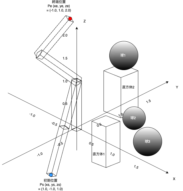
環境内の干渉物の情報は下表の通りである.
| 干渉物名 | 中心点 [m] | 情報1 [m] |
|---|---|---|
| 直方体1 | $(x, y, z) = (1.4, -0.6, 1.5)$ | 箱の長さ$(x, y, z) = (0.4, 0.3, 0.8)$ |
| 直方体2 | $(x, y, z) = (1.2, 0.7, 2.0)$ | 箱の長さ$(x, y, z) = (0.6, 0.8, 1.0)$ |
| 球1 | $(x, y, z) = (0.5, 1.5, 1.5)$ | 半径 $0.5$ |
| 球2 | $(x, y, z) = (1.5, 0.3, 1.5)$ | 半径 $0.3$ |
| 球3 | $(x, y, z) = (1.5, 0.5, 1.0)$ | 半径 $0.5$ |
本環境を定義するソースコード (environment.py)
経路生成したい環境を定義するソースコードを書きに記す.
本記事では,下記の Robot3DEnv() クラスで定義した環境を使用する.
# 環境の作成

# 標準ライブラリの読み込み
import numpy as np

# サードパーティーの読み込み
import fcl

# 自作モジュールの読み込み
from constant import *              # 定数
from rotation import Rotation       # 回転行列


class Base3DEnv:
    """
    経路生成時の3次元環境

    プロパティ
        _distance(float): 干渉物との最短距離
        _inteferences(dist): 干渉物の情報 (名称(球や直方体など) + 形状(半径,中心点など))

    メソッド
        public
            inteferences(): _inteferencesプロパティのゲッター
            distance(): _distanceプロパティのゲッター
            is_collision(): 干渉判定
            is_collision_dist(): 干渉判定 + 最短距離
    """
    # 定数の定義
    _INITIAL_MARGIN = 0.0   # 干渉物とのマージン [m]

    def __init__(self):
        """
        コンストラクタ
        """
        objects = []
        self._interferences = {}

        # 球の干渉物を定義 (球の位置 (x, y, z) と半径を定義)
        balls = [[0.8, 0.8, 0.8, 0.3], [1.2, 0.8, 0.8, 0.3], [1.2, 1.2, 1.2, 0.3], [0.8, 1.2, 1.2, 0.3]]
        for x, y, z, radius in balls:
            # 球の半径を設定
            ball = fcl.Sphere(radius)
            # 球の中心点を平行移動
            translation = fcl.Transform(np.array([x, y, z]))
            obj = fcl.CollisionObject(ball, translation)
            # モデルを追加
            objects.append(obj)
        # 球の干渉物を保存
        self._interferences[INTERFERENCE.BALL] = balls

        # # 直方体の干渉物を定義
        # # 直方体の長さ (x, y, z) と中心点の位置 (x, y, z)
        # cuboids = [[0.2, 0.3, 0.3, 0.6, 0.6, 0.6], [0.4, 0.5, 0.6, 0.8, 1.0, 1.0], [1.0, 1.0, 1.0, 0.8, 0.8, 0.8]]
        # for x, y, z, center_x, center_y, center_z in cuboids:
        #     # 直方体の各辺の長さを設定
        #     cuboid = fcl.Box(x, y, z)
        #     # 長方形の中心点を設定.無回転とする
        #     translation = fcl.Transform(np.array([center_x, center_y, center_z]))
        #     obj = fcl.CollisionObject(cuboid, translation)
        #     # モデルを追加
        #     objects.append(obj)
        # # 直方体の干渉物を保存
        # self._interferences[INTERFERENCE.CUBOID] = cuboids

        # DynamicAABBTreeCollisionManager に登録
        self._manager = fcl.DynamicAABBTreeCollisionManager()
        self._manager.registerObjects(objects)
        self._manager.setup()

        # 最短距離を更新
        self._distance = 0.0

    @property
    def distance(self):
        """
        _distanceプロパティのゲッター
        """
        return self._distance

    @property
    def interferences(self):
        """
        _interferencesプロパティのゲッター (描画で使用する)
        """
        return self._interferences

    def is_collision(self, obj):
        """
        干渉判定

        パラメータ
            obj(fcl.CollisionObject): 干渉物

        戻り値
            is_collision(bool): True / False = 干渉あり / 干渉なし
        """
        # 衝突リクエスト
        # num_max_contacts ... 最大の衝突点数
        # enable_contact ... 衝突点情報の有無
        request  = fcl.CollisionRequest(num_max_contacts=100, enable_contact=True)
        col_data = fcl.CollisionData(request=request)

        # 本環境と干渉物の干渉判定
        self._manager.collide(obj, col_data, fcl.defaultCollisionCallback)

        return col_data.result.is_collision

    def is_collision_dist(self, obj, margin=_INITIAL_MARGIN):
        """
        干渉判定 + 最短距離

        パラメータ
            obj(fcl.CollisionObject): 干渉物
            margin(float): 干渉判定のマージン [m]

        戻り値
            collision(bool): True / False = 干渉あり / 干渉なし
        """
        # 引数確認
        if margin < 0:
            margin = self._INITIAL_MARGIN

        dist_data   = fcl.DistanceData()

        # 最短距離の結果を保存する
        self._manager.distance(obj, dist_data, fcl.defaultDistanceCallback)
        min_dist = dist_data.result.min_distance
        # 最短距離の更新
        self._distance = min_dist
        # print(f"min_dist = {min_dist}")

        if min_dist > margin:
            # 干渉なし
            collision = False
        else:
            # 干渉あり
            collision = True

        return collision


class Robot3DEnv(Base3DEnv):
    """
    経路生成時の3次元環境 (ロボット用)

    プロパティ
        _distance(float): 干渉物との最短距離
        _inteferences(dist): 干渉物の情報 (名称(円や長方形など) + 形状(半径,中心点など))

    メソッド
        public
            inteferences(): _inteferencesプロパティのゲッター
            distance(): _distanceプロパティのゲッター
            is_collision(): 干渉判定
            is_collision_dist(): 干渉判定 + 最短距離
    """
    # 定数の定義

    def __init__(self):
        """
        コンストラクタ
        """
        objects = []
        self._interferences = {}
        self._rot = Rotation()

        # 円形の干渉物を定義 (円の位置 (x, y, z) と半径を定義)
        balls = [[0.5, 1.5, 1.5, 0.5], [1.5, 0.3, 1.5, 0.3], [1.5, 0.5, 1.0, 0.5]]
        for x, y, z, radius in balls:
            # fclに円が定義されていないため,球とする
            ball = fcl.Sphere(radius)
            # 円の中心点が原点であるため,中心点を平行移動させる
            translation = fcl.Transform(np.array([x, y, z]))
            obj = fcl.CollisionObject(ball, translation)
            # モデルを追加
            objects.append(obj)
        # 円形の干渉物を保存
        self._interferences[INTERFERENCE.BALL] = balls

        # 直方体の干渉物を定義
        # 直方体の長さ (x, y, z) と中心点の位置 (x, y, z),x,y,z軸の回転角度 [deg]
        cuboids = [[0.4, 0.3, 0.8, 1.4, -0.6, 1.5, 0, 0, 0], [0.6, 0.8, 1.0, 1.2, 0.7, 2.0, 0, 0, 0]]
        for x, y, z, center_x, center_y, center_z, angle_x, angle_y, angle_z in cuboids:
            # 直方体の長さ (x, y, z) を設定
            cuboid = fcl.Box(x, y, z)
            # 回転行列の作成
            rotation_x = self._rot.rot(np.deg2rad(angle_x), ROTATION_X_AXIS)
            rotation_y = self._rot.rot(np.deg2rad(angle_y), ROTATION_Y_AXIS)
            rotation_z = self._rot.rot(np.deg2rad(angle_z), ROTATION_Z_AXIS)
            rotation = np.dot(rotation_z, np.dot(rotation_y, rotation_x))
            # 長方形の中心点,回転行列を設定
            translation = fcl.Transform(rotation, np.array([center_x, center_y, center_z]))
            obj = fcl.CollisionObject(cuboid, translation)
            # モデルを追加
            objects.append(obj)
        # 長方形の干渉物を保存
        self._interferences[INTERFERENCE.CUBOID] = cuboids

        # DynamicAABBTreeCollisionManager に登録
        self._manager = fcl.DynamicAABBTreeCollisionManager()
        self._manager.registerObjects(objects)
        self._manager.setup()

        # 最短距離を更新
        self._distance = 0.0
姿勢を定義するソースコード (rotation.py)
姿勢(回転行列)を定義するソースコードを下記に示す.
# 回転行列の定義

# 標準ライブラリの読み込み
import numpy as np


# サードパーティーの読み込み


# 自作モジュールの読み込み
from constant import *      # 定数


class Rotation:
    """
    回転行列クラス
    """

    def _rot_x(self, theta):
        """
        x軸方向にtheta[rad]回転させる回転行列

        パラメータ
            theta(float): 回転角度 [rad]

        戻り値
            rotation(numpy.ndarray): 回転行列
        """
        rotation = np.array([[1, 0,              0            ],
                             [0, np.cos(theta), -np.sin(theta)],
                             [0, np.sin(theta),  np.cos(theta)]])

        return rotation

    def _rot_y(self, theta):
        """
        y軸方向にtheta[rad]回転させる回転行列

        パラメータ
            theta(float): 回転角度 [rad]

        戻り値
            rotation(numpy.ndarray): 回転行列
        """
        rotation = np.array([[ np.cos(theta), 0, np.sin(theta)],
                             [ 0,             1, 0            ],
                             [-np.sin(theta), 0, np.cos(theta)]])

        return rotation

    def _rot_z(self, theta):
        """
        z軸方向にtheta[rad]回転させる回転行列

        パラメータ
            theta(float): 回転角度 [rad]

        戻り値
            rotation(numpy.ndarray): 回転行列
        """
        rotation = np.array([[np.cos(theta), -np.sin(theta), 0],
                             [np.sin(theta),  np.cos(theta), 0],
                             [0,              0,             1]])

        return rotation

    def rot(self, theta, axis):
        """
        回転軸に応じた回転行列の取得

        パラメータ
            theta(float): 回転角度 [rad]
            axis(str): 回転軸

        戻り値
            rotation(numpy.ndarray): 回転行列
        """
        if axis == ROTATION_X_AXIS:
            # 回転軸がx軸
            rotation = self._rot_x(theta)
        elif axis == ROTATION_Y_AXIS:
            # 回転軸がy軸
            rotation = self._rot_y(theta)
        elif axis == ROTATION_Z_AXIS:
            # 回転軸がz軸
            rotation = self._rot_z(theta)
        elif axis == ROTATION_Y_NEGATIVE_AXIS:
            # 回転軸がy軸だが,逆回転
            rotation = self._rot_y(-theta)
        elif axis == ROTATION_Z_NEGATIVE_AXIS:
            # 回転軸がz軸だが,逆回転
            rotation = self._rot_z(-theta)
        else:
            # 異常
            raise ValueError(f"axis is abnormal. now is {axis}")

        return rotation
3軸ロボットアームに関して
3軸ロボットアームは下図を想定している.
リンク1はz軸に$\theta_{1}$回転,リンク2はy軸に$\theta_{2}$回転,リンク3はy軸に$\theta_{3}$回転する,3軸ロボットアームを考えている.
$\theta_{1} = 0$かつ$\theta_{2} = 0$かつ$\theta_{3} = 0$の時,ロボットの手先位置は$(x, y, z) = (l_{2} + l_{3}, 0, l_{1})$となる.

3軸ロボットアームの順運動学 (関節角度から手先位置を算出する)
3軸ロボットアームの順運動学は下記に記載したため,割愛する.
・https://qiita.com/haruhiro1020/items/27c0cf098056dc792ab9
3軸ロボットアームの逆運動学 (手先位置から関節角度を算出する)
3軸ロボットアームの逆運動学は下記に記載したため,割愛する.
・https://qiita.com/haruhiro1020/items/3d72eddc3f623eee963a
3軸ロボットアームの直方体化
3軸ロボットアームを干渉判定させるためには,各リンクを直方体と考える必要がある.
各リンクの直方体としての値は下表のように考えている.
| リンク名 | x [m] | y [m] | z [m] |
|---|---|---|---|
| 1 | $0.04$ | $0.04$ | $l_{1}(1.0)$ |
| 2 | $l_{2}(1.0)$ | $0.04$ | $0.04$ |
| 3 | $l_{3}(1.0)$ | $0.04$ | $0.04$ |
3軸ロボットアームを定義するソースコード (robot.py)
3軸ロボットアームを定義するソースコードを下記に記す.
ロボットアームの各リンクの直方体の位置・姿勢を更新する必要があるため,update()メソッドで更新する.
本記事では,下記の Robot3DoF() クラスで定義したロボットを使用する.
# ロボットアームの運動学を記載

# ライブラリの読み込み
import numpy as np

# サードパーティーの読み込み
import fcl

# 自作モジュールの読み込み
from constant import *              # 定数
from rotation import Rotation       # 回転行列


class Robot:
    """
    ロボットのベースクラス(抽象クラス)

    プロパティ
        _links(numpy.ndarray): ロボットのリンク長 [m]
        _rot(Rotation): 回転行列クラス
        _objects(list): 干渉物オブジェクト
        _manager(fcl.DynamicAABBTreeCollisionManager): 干渉判定クラス

    メソッド
        public
            forward_kinematics(): 順運動学 (ロボットの関節角度からロボットの手先位置を算出)
            inverse_kinematics(): 逆運動学 (ロボットの手先位置からロボットの関節角度を算出)
            forward_kinematics_all_pos(): 順運動学で全リンクの位置を取得
            update(): 角度を与えて,各リンクの直方体を更新する
            links(): _linksプロパティのゲッター
            manager(): _managerプロパティのゲッター
    """
    # 定数の定義
    _DIMENTION_POSE  = DIMENTION_NONE       # 手先位置の次元数
    _DIMENTION_THETA = DIMENTION_NONE       # 関節角度の次元数
    _DIMENTION_LINK  = DIMENTION_NONE       # リンク数
    _DIMENTION_AXIS  = DIMENTION_NONE       # 回転軸数

    _INITIAL_THETA   = 0.0                  # 初期回転角度 [rad]


    def __init__(self, links):
        """
        コンストラクタ

        パラメータ
            links(numpy.ndarray): ロボットのリンク長 [m]
        """
        if np.size(links) != self._DIMENTION_LINK:
            # 異常
            raise ValueError(f"links's size is abnormal. correct is {self._DIMENTION_Link}")

        # プロパティの初期化
        self._links = links
        self._rot = Rotation()
        self._objects = []
        self._manager = None

    @property
    def links(self):
        """
        _linksプロパティのゲッター
        """
        return self._links

    @property
    def manager(self):
        """
        _managerプロパティのゲッター
        """
        return self._manager

    def forward_kinematics(self, thetas):
        """
        順運動学 (ロボットの関節角度からロボットの手先位置を算出)

        パラメータ
            thetas(numpy.ndarray): ロボットの関節角度 [rad]

        戻り値
            pose(numpy.ndarray): ロボットの手先位置 (位置 + 姿勢) [m] + [rad]
        """
        raise NotImplementedError("forward_kinematics() is necessary override.")

    def inverse_kinematics(self, pose):
        """
        逆運動学 (ロボットの手先位置からロボットの関節角度を算出)

        パラメータ
            pose(numpy.ndarray): ロボットの手先位置 (位置 + 姿勢) [m] + [rad]

        戻り値
            thetas(numpy.ndarray): ロボットの関節角度 [rad]
        """
        raise NotImplementedError("inverse_kinematics() is necessary override.")

    def forward_kinematics_all_pos(self, thetas):
        """
        順運動学で全リンクの位置を取得

        パラメータ
            thetas(numpy.ndarray): ロボットの関節角度 [rad]

        戻り値
            all_pose(numpy.ndarray): ロボットの全リンク位置 (位置 + 姿勢) [m] + [rad]
        """
        raise NotImplementedError("forward_kinematics() is necessary override.")

    def update(self, thetas):
        """
        角度を与えて,各リンクの直方体を更新する

        パラメータ
            thetas(numpy.ndarray): ロボットの関節角度 [rad]
        """
        raise NotImplementedError("update() is necessary override.")


class Robot3DoF(Robot):
    """
    3軸ロボットクラス

    プロパティ
        _links(numpy.ndarray): ロボットのリンク長
        _rot(Rotation): 回転行列クラス
        _axiss(list): 関節の回転軸

    メソッド
        public
            forward_kinematics(): 順運動学 (ロボットの関節角度からロボットの手先位置を算出)
            inverse_kinematics(): 逆運動学 (ロボットの手先位置からロボットの関節角度を算出)
            forward_kinematics_all_pos(): 順運動学で全リンクの位置を取得
            update(): 角度を与えて,各リンクの直方体を更新する
    """
    # 定数の定義
    _DIMENTION_POSE  = DIMENTION_3D         # 手先位置の次元数
    _DIMENTION_THETA = DIMENTION_3D         # 関節角度の次元数
    _DIMENTION_LINK  = DIMENTION_3D         # リンク数

    _DETERMINANT_THRESHOLD = 1e-4           # 行列式の閾値
    _THETA1_XY_THRESHOLD   = 1e-4           # theta1算出時のx, y閾値
    _BOX_WIDTH = 1e-1                       # 各リンクの幅を定義


    def __init__(self, links):
        """
        コンストラクタ

        パラメータ
            links(numpy.ndarray): ロボットのリンク長 [m]
        """
        # 親クラスの初期化
        super().__init__(links)
        # ロボットの各リンクを直方体として定義する
        self._objects = []

        # リンク1は回転軸がz軸,リンク2とリンク3は回転軸がy軸である
        self._axiss = [ROTATION_Z_AXIS, ROTATION_Y_NEGATIVE_AXIS, ROTATION_Y_NEGATIVE_AXIS]
        # 初期角度
        initial_thetas = np.zeros(self._DIMENTION_THETA)
        # 順運動学により,全リンク(ベースリンク,リンク1,リンク2,リンク3)の位置を計算
        all_link_pose = self.forward_kinematics_all_link_pos(initial_thetas)

        # 1つ前のリンクの回転行列を更新
        prev_rotation = np.eye(3)

        # 各リンクの角度が全部0の時のx, y, zを定義
        box_xyz = [[self._BOX_WIDTH * 2, self._BOX_WIDTH * 2, self._links[0]     ],
                   [self._links[1],      self._BOX_WIDTH * 2, self._BOX_WIDTH * 2],
                   [self._links[2],      self._BOX_WIDTH * 2, self._BOX_WIDTH * 2]]

        # ロボットの各リンクを直方体として定義する
        for i in range(self._DIMENTION_THETA):
            # 各リンクの回転行列を定義
            rotation = self._rot.rot(initial_thetas[i], self._axiss[i])
            rotation = np.dot(prev_rotation, rotation)
            # 各リンクの中心位置 (x, y, z) を定義
            center = (all_link_pose[i + 1] - all_link_pose[i]) / 2 + all_link_pose[i]
            # 直方体の定義 (x, y, zの長さを保存)
            x, y, z = box_xyz[i]
            box = fcl.Box(x, y, z)
            # 直方体の中心を定義 (位置・姿勢)
            translation = fcl.Transform(rotation, center)
            obj = fcl.CollisionObject(box, translation)
            # モデルを追加
            self._objects.append(obj)
            # 1つ前のリンクの回転行列を更新
            prev_rotation = rotation

        # 直方体をAABBとして,定義
        # DynamicAABBTreeCollisionManager に登録
        self._manager = fcl.DynamicAABBTreeCollisionManager()
        self._manager.registerObjects(self._objects)
        self._manager.setup()

    def forward_kinematics(self, thetas):
        """
        順運動学 (ロボットの関節角度からロボットの手先位置を算出)

        パラメータ
            thetas(numpy.ndarray): ロボットの関節角度 [rad]

        戻り値
            pose(numpy.ndarray): ロボットの手先位置 (位置) [m]
        """
        # パラメータの次元数を確認
        if np.size(thetas) != self._DIMENTION_THETA:
            raise ValueError(f"thetas's size is abnormal. thetas's size is {np.size(thetas)}")

        # あらかじめ三角関数を算出する
        sin1  = np.sin(thetas[0])
        sin2  = np.sin(thetas[1])
        sin23 = np.sin(thetas[1] + thetas[2])
        cos1  = np.cos(thetas[0])
        cos2  = np.cos(thetas[1])
        cos23 = np.cos(thetas[1] + thetas[2])

        # ロボットの手先位置を算出
        pxy_common = self._links[1] * cos2 + self._links[2] * cos23
        px = cos1 * pxy_common
        py = sin1 * pxy_common
        pz = self._links[0] + self._links[1] * sin2 + self._links[2] * sin23
        pose = np.array([px, py, pz])

        return pose

    def inverse_kinematics(self, pose, upper=False, front=True):
        """
        逆運動学 (ロボットの手先位置からロボットの関節角度を算出)

        パラメータ
            pose(numpy.ndarray): ロボットの手先位置 (位置) [m]
            upper(bool): 腕が上向かどうか
            front(bool): 正面かどうか

        戻り値
            thetas(numpy.ndarray): ロボットの関節角度 [rad]
        """
        # パラメータの次元数を確認
        if np.size(pose) != self._DIMENTION_POSE:
            raise ValueError(f"parameter pose's size is abnormal. pose's size is {np.size(pose)}")

        # はじめにtheta3を算出する
        # c3 = {(px ** 2 + py ** 2 + (pz - l1) ** 2) - (l2 ** 2 + l3 ** 2)} / (2 * l2 * l3)
        px = pose[0]
        py = pose[1]
        pz = pose[2]
        l1 = self._links[0]
        l2 = self._links[1]
        l3 = self._links[2]
        cos3  = ((px ** 2 + py ** 2 + (pz - l1) ** 2) - (l2 ** 2 + l3 ** 2)) / (2 * l2 * l3)
        # cosの範囲は-1以上1以下である
        if abs(cos3) > 1:
            # 異常
            raise ValueError(f"cos3 is abnormal. cos3 is {cos3}")

        # sinも求めて,theta3をatan2(sin2, cos2)より算出する
        sin3 = np.sqrt(1 - cos3 ** 2)
        theta3 = np.arctan2(sin3,  cos3)
        if not upper:
            # 下向きの角度のため,三角関数も更新
            theta3 = -theta3
            sin3 = np.sin(theta3)
            cos3 = np.cos(theta3)

        # 次にtheta1を算出する
        # theta1 = atan2(py, px)
        # py, pxが0近傍なら失敗
        if abs(py) <= self._THETA1_XY_THRESHOLD and abs(px) <= self._THETA1_XY_THRESHOLD:
            # 近傍のため,エラー
            raise ValueError(f"abs(py) and abs(px) is abnormal. py is {py}, px is {px}")
        if front:
            # 位置(pose)に対して正面向き
            theta1 = np.arctan2( py,  px)
        else:
            # 位置(pose)に対して後ろ向き
            theta1 = np.arctan2(-py, -px)

        # 最後にtheta2を算出する
        # 行列計算
        # [c2, s2] = [[l2 + l3 * c3, -l3 * s3], [l3 * s3, l2 + l3 * c3]] ** -1 * [root(px ** 2 + py ** 2), pz - l1]
        element1 =  l2 + l3 * cos3
        element2 = -l3 * sin3
        matrix = np.array([[ element1, element2],
                           [-element2, element1]])
        # 行列式を計算
        det = np.linalg.det(matrix)
        # 0近傍の確認
        if abs(det) <= self._DETERMINANT_THRESHOLD:
            # 0近傍 (異常)
            raise ValueError(f"det is abnormal. det is {det}")

        # 位置を保存 ([root(px ** 2 + py ** 2), pz - l1])
        position = np.array([np.sqrt(px ** 2 + py ** 2), pz - l1])

        # [c2, s2]の計算
        cos2_sin2 = np.dot(np.linalg.inv(matrix), position)
        # theta2をatan2()より算出する
        theta2 = np.arctan2(cos2_sin2[1], cos2_sin2[0])

        thetas = np.array([theta1, theta2, theta3])

        return thetas

    def forward_kinematics_all_link_pos(self, thetas):
        """
        順運動学で全リンクの位置を取得 (グラフの描画で使用する)

        パラメータ
            thetas(numpy.ndarray): ロボットの関節角度 [rad]

        戻り値
            all_link_pose(numpy.ndarray): ロボットの全リンク位置 (位置 + 姿勢) [m] + [rad]
        """
        # パラメータの次元数を確認
        if np.size(thetas) != self._DIMENTION_THETA:
            raise ValueError(f"thetas's size is abnormal. thetas's size is {np.size(thetas)}")

        # 回転角度とリンク長をローカル変数に保存
        theta1 = thetas[0]
        theta2 = thetas[1]
        theta3 = thetas[2]
        link1  = self._links[0]
        link2  = self._links[1]
        link3  = self._links[2]

        # 三角関数を計算
        s1  = np.sin(theta1)
        c1  = np.cos(theta1)
        s2  = np.sin(theta2)
        c2  = np.cos(theta2)
        s3  = np.sin(theta3)
        c3  = np.cos(theta3)
        s12 = np.sin(theta1 + theta2)
        c12 = np.cos(theta1 + theta2)
        s23 = np.sin(theta2 + theta3)
        c23 = np.cos(theta2 + theta3)

        # 各リンクの位置を算出
        base_pos  = np.zeros(self._DIMENTION_POSE)
        link1_pos = np.array([0, 0, link1])
        link2_xy_common = link2 * c2
        link2_pos = np.array([c1 * link2_xy_common, s1 * link2_xy_common, link1 + link2 * s2])
        link3_xy_common = link2 * c2 + link3 * c23
        link3_pos = np.array([c1 * link3_xy_common, s1 * link3_xy_common, link1 + link2 * s2 + link3 * s23])

        # 全リンクの位置を算出
        all_link_pose = np.array([base_pos, link1_pos, link2_pos, link3_pos])

        return all_link_pose

    def update(self, thetas):
        """
        角度を与えて,各リンクの直方体を更新する

        パラメータ
            thetas(numpy.ndarray): ロボットの関節角度 [rad]
        """
        # パラメータの次元数を確認
        if np.size(thetas) != self._DIMENTION_THETA:
            raise ValueError(f"thetas's size is abnormal. thetas's size is {np.size(thetas)}")

        # 順運動学により,全リンク(ベースリンク,リンク1,リンク2,リンク3)の位置を計算
        all_link_pose = self.forward_kinematics_all_link_pos(thetas)
        # 1つ前のリンクの回転行列を定義
        prev_rotation = np.eye(3)

        # ロボットの各リンクを直方体として定義する
        for i in range(self._DIMENTION_THETA):
            # 各リンクの回転行列を定義
            rotation = self._rot.rot(thetas[i], self._axiss[i])
            # 1つ前のリンクの回転も考慮する
            rotation = np.dot(prev_rotation, rotation)
            # 各リンクの中心位置 (x, y, z) を定義
            center = (all_link_pose[i + 1] - all_link_pose[i]) / 2 + all_link_pose[i]
            # print(f"center = {center}")
            # 直方体の中心を定義 (位置・姿勢)
            translation = fcl.Transform(rotation, center)
            # モデルの位置を更新
            self._objects[i].setTransform(translation)
            # 1つ前のリンクの回転行列を更新
            prev_rotation = rotation

        # AABBを更新
        self._manager.update()
RRTに関して
RRTのアルゴリズムに関して
RRTのアルゴリズムに関しての説明は下記で説明したため,割愛する.
・https://qiita.com/haruhiro1020/items/6eaae645bd638c2b8897
RRTで探索する空間に関して
以前の"2軸ロボットアームでRRTによる経路生成(https://qiita.com/haruhiro1020/items/b42725df00e13ddcb5af)" 記事にて,軌道生成には関節空間(始点位置と終点位置を逆運動学にて,角度に変換して,始点角度から終点角度への経路を探索する)と位置空間(始点位置から終点位置への経路を生成する)での探索があることを説明した.
今回は,探索空間を関節または位置と選択できるようにする.
RRTに環境と3軸ロボットアームを使用できるようにするソースコード (rrt.py)
RRTを定義するソースコードを書きに記す.
本記事では,下記の RRTRobot() クラスで定義したRRTを使用する.
# 経路生成手法であるRRT (Rapidly-exploring Random Tree) の実装

# ライブラリの読み込み
import numpy as np
import time

# 自作モジュールの読み込み
from constant import *              # 定数
from environment import Robot3DEnv  # 環境


class Tree:
    """
    ツリークラス

    プロパティ
        _nodes(numpy.ndarray): ノード
        _near_node_idx(int): _nodes内の最短ノードを保存している列番号

    メソッド
        public
            nodes(): _nodesプロパティのゲッター
            add_node(): ノードの追加
            get_near_node(): 最短距離のノードを取得
    """
    # 定数の定義

    def __init__(self, near_node_idx):
        """
        コンストラクタ
        """
        # プロパティの初期化
        self._nodes = []
        self._near_node_idx = near_node_idx

    @property
    def nodes(self):
        """
        _nodesプロパティのゲッター
        """
        return self._nodes

    def reset(self):
        """
        データの初期化
        """
        if len(self._nodes) != 0:
            # 何かしらのデータが保存
            del self._nodes
        self._nodes  =[]

    def add_node(self, node):
        """
        ノードの追加

        パラメータ
            node(numpy.ndarray): ノード
        """
        if len(self._nodes) == 0:       # 初回だけ実行
            self._nodes = node
        else:
            self._nodes = np.append(self._nodes, node, axis=0)

    def _chk_node_exist(self):
        """
        ノードが存在するかの確認
        """
        if len(self._nodes) == 0:
            # 存在しない
            raise ValueError("self_nodes is not exist")

    def get_near_node(self, pos):
        """
        最短距離のノードを取得

        パラメータ
            pos(numpy.ndarray): 位置

        戻り値
            min_dist_idx(int): 最短距離のノード番号
        """
        # ノードの存在確認
        self._chk_node_exist()

        # ノードから位置を取得
        nodes_pos  = self._nodes[:, :self._near_node_idx]
        # 差分を計算
        difference = nodes_pos - pos
        # 距離を計算
        distance   = np.linalg.norm(difference, axis=1)
        # 最短距離ノードを取得
        min_dist_idx = np.argmin(distance)

        return min_dist_idx

    def get_near_node_list(self, pos, radius):
        """
        ノードと近傍ノードをリストで取得

        パラメータ
            pos(numpy.ndarray): ノード位置
            radius(float): 半径

        戻り値
            near_node_list(list): 近傍ノードリスト
        """
        # ノードの存在確認
        self._chk_node_exist()

        near_node_list = []
        # ツリー内全ノード位置を取得
        all_node_pos = self._nodes[:, :self._near_node_idx]
        # ノードとツリー内全ノードの差分を計算
        difference   = all_node_pos - pos
        # 差分から距離(ユークリッド距離)を計算
        distance     = np.linalg.norm(difference, axis=1)

        # 距離が一定以内のノードだけを保存
        near_node_list = [idx for idx, dist in enumerate(distance) if dist <= radius]

        return near_node_list


class RRTRobot:
    """
    RRTにロボットを追加したクラス

    プロパティ
        _pathes(numpy.ndarray): 始点から終点までの経路
        _start_tree(Tree): 始点ツリー
        _start_random_tree(Tree): ランダムな位置を保存した始点ツリー
        _strict_min_pos(numpy.ndarray): 探索の最小範囲
        _strict_max_pos(numpy.ndarray): 探索の最大範囲
        _environment(Base2DEnv): 経路生成したい環境
        _debug(bool): デバッグフラグ (グラフやアニメーションでデータを確認したいかどうか)
        _robot(Robot): ロボットクラス
        _moving_value(float): 1回あたりの移動量 [rad] or [m]

    メソッド
        public
            planning(): 経路生成の実装
            pathes(): _pathesプロパティのゲッター
            start_tree(): _treeプロパティのゲッター
            start_random_tree(): _random_treeプロパティのゲッター
            strict_min_pos(): _strict_min_posプロパティのゲッター
            strict_max_pos(): _strict_max_posプロパティのゲッター
            environment(): _environmentプロパティのゲッター

        protected
            _reset(): データの初期化
            _add_node(): ツリーにノードを追加する
            _chk_end_pos_dist(): 終点との距離が一定範囲内であるかの確認
            _fin_planning(): 経路生成の終了処理
            _calc_new_pos(): 最短ノードからランダムな値方向へ新しいノード(位置)を作成
            _strict_planning_pos(): 探索範囲を制限する
            _get_random_pos(): ランダムな位置を取得
            _line_interference(): 2点間の干渉チェック
            _is_interference_pos(): 干渉判定処理
            _save(): データの保存
    """
    # 定数の定義
    # ファイル名の定義
    _FILE_NAME_PATHES = "rrt_pathes.csv"                        # _pathesプロパティを保存するファイル名
    _FILE_NAME_START_TREE = "rrt_start_tree.csv"                # _start_treeプロパティを保存するファイル名
    _FILE_NAME_START_RANDOM_TREE = "rrt_start_random_tree.csv"  # _start_random_treeプロパティを保存するファイル名

    # ツリーの要素番号を定義
    _NODE_NEAR_NODE_IDX = RRT_NEAR_NODE_IDX     # ノード内の最短ノード要素

    # 干渉判定の定義
    _DEVIDED_DISTANCE_POS   = 0.05      # 2点間を分割する際の基準距離 [m]
    _DEVIDED_DISTANCE_JOINT = 0.01      # 2点間を分割する際の基準距離 [rad]
    _INTERFERENCE_MARGIN    = 0.2      # 干渉物とのマージン (最短距離がマージンよりも小さかったら干渉ありとする) [m]

    # 探索に関する定義
    _MOVING_VALUE_JOINT = 0.1         # 1回の移動量 [rad] (ロボットの関節空間)
    _MOVING_VALUE_POS   = 0.2         # 1回の移動量 [m] (ロボットの位置空間)
    _STRICT_PLANNING_ROB_JOINT = 1.5  # 探索範囲の制限 [rad] (ロボットの関節空間)
    _STRICT_PLANNING_ROB_POS   = 0.5  # 探索範囲の制限 [m] (ロボットの位置空間)

    _TIMEOUT_VALUE = 10         # タイムアウト時間 [second]
    _GOAL_SAMPLE_RATE = 0.1     # ランダムな値を取るときに,終点を選択する確率


    def __init__(self):
        """
        コンストラクタ
        """
        self._start_tree = Tree(self._NODE_NEAR_NODE_IDX)
        self._start_random_tree = Tree(self._NODE_NEAR_NODE_IDX)
        self._pathes = []
        self._environment = None
        self._debug = False
        self._robot = None
        self._interpolation = INTERPOLATION.JOINT
        self._moving_value  = self._MOVING_VALUE_JOINT

    @property
    def start_tree(self):
        """
        _start_treeプロパティのゲッター
        """
        return self._start_tree

    @property
    def start_random_tree(self):
        """
        _start_random_treeプロパティのゲッター
        """
        return self._start_random_tree

    @property
    def pathes(self):
        """
        _pathesプロパティのゲッター
        """
        return self._pathes

    @property
    def strict_min_pos(self):
        """
        _strict_min_posプロパティのゲッター
        """
        return self._strict_min_pos

    @property
    def strict_max_pos(self):
        """
        _strict_max_posプロパティのゲッター
        """
        return self._strict_max_pos

    def _add_node_start_tree(self, pos, random_pos, near_node):
        """
        始点ツリーにノードを追加

        パラメータ
            pos(numpy.ndarray): 位置
            random_pos(numpy.ndarray): ランダムな位置
            near_node(int): 最短ノード
        """
        # _start_treeにノードを追加
        node = np.append(pos, near_node).reshape(1, -1)
        self._start_tree.add_node(node)

        # デバッグ有効の時しか,ランダムなツリーにデータを保存したくない (処理時間の短縮)
        if self._debug:
            # _start_random_treeにノードを追加
            random_node = np.append(random_pos, near_node).reshape(1, -1)
            self._start_random_tree.add_node(random_node)

    def _reset(self):
        """
        データの初期化
        """
        self._start_tree.reset()
        self._start_random_tree.reset()

        if len(self._pathes) != 0:
            # 何かしらのデータが保存
            del self._pathes
        self._pathes = []

        if self._environment is None:
            del self._environment
        self._environment = None

        if self._robot is None:
            del self._robot
        self._robot = None
        self._interpolation = INTERPOLATION.JOINT

    def _set_robot(self, robot, interpolation):
        """
        経路生成したいロボット情報を設定

        パラメータ
            robot(Robot): ロボットクラス
            interpolation(int): 補間の種類 (関節補間/位置補間)
        """
        self._robot = robot
        if interpolation == INTERPOLATION.POSITION:
            # 位置空間
            self._interpolation = INTERPOLATION.POSITION
            self._moving_value  = self._MOVING_VALUE_POS
        else:
            # 関節空間
            self._interpolation = INTERPOLATION.JOINT
            self._moving_value  = self._MOVING_VALUE_JOINT

    def planning(self, start_pos, end_pos, environment, robot, interpolation, debug=False):
        """
        経路生成

        パラメータ
            start_pos(list): 経路生成の始点
            end_pos(list): 経路生成の終点
            environment(Base2DEnv): 環境
            robot(Robot): ロボットクラス
            interpolation(int): 補間方法 (関節空間/位置空間)
            debug(bool): デバッグフラグ

        戻り値
            result(bool): True / False = 成功 / 失敗
        """
        # 処理結果
        result = False

        # デバッグフラグの更新
        self._debug = debug
        # データの初期化
        self._reset()

        # 始点と終点の次元数が一致しているかの確認
        start_pos_dim = np.size(start_pos)
        end_pos_dim   = np.size(end_pos)
        if start_pos_dim != end_pos_dim:
            # 次元数が異なるので異常
            raise ValueError(f"start_pos_dim and end_pos_dim are not matched. start_pos_dim is {start_pos_dim}, end_pos_dim is {end_pos_dim}")

        self._dim = start_pos_dim

        # 環境を設定
        self._environment = environment
        # ロボットの設定
        self._set_robot(robot, interpolation)

        # 始点と終点の干渉判定
        if self._interference_pos(start_pos):
            # 干渉ありまたは逆運動学の解が求まらない
            raise ValueError(f"start_pos is interference. please change start_pos")

        if self._interference_pos(end_pos):
            # 干渉ありまたは逆運動学の解が求まらない
            raise ValueError(f"end_pos is interference. please change end_pos")

        # 始点ノードを設定
        self._add_node_start_tree(start_pos, start_pos, INITIAL_NODE_NEAR_NODE)
        # 探索する範囲を設定
        self._strict_planning_pos(start_pos, end_pos)

        # 経路生成は一定時間内に終了させる
        start_time = time.time()

        # 終点までの経路生成が終わるまでループ
        while True:
        # for _ in range(1000):
            # ランダムな値を取得
            random_pos = self._get_random_pos(end_pos)
            # ランダムな値と最短ノードを計算
            near_node = self._start_tree.get_near_node(random_pos)
            # 最短ノードの位置
            near_node_pos = self._start_tree.nodes[near_node, :self._NODE_NEAR_NODE_IDX]
            # 最短ノードからランダムな値方向へ新しいノード(位置)を作成
            new_pos = self._calc_new_pos(random_pos, near_node_pos)

            # 新規ノードと最短ノード間での干渉判定
            is_interference = self._line_interference(new_pos, near_node_pos)
            if not is_interference:
                # 干渉なしのため,ノードを設定する
                self._add_node_start_tree(new_pos, random_pos, near_node)

                # 終点との距離が一定範囲内であるかの確認
                if self._chk_end_pos_dist(new_pos, end_pos):
                    # 一定範囲内のため,経路生成の完了
                    result = True
                    break

            now_time = time.time()
            if now_time - start_time >= self._TIMEOUT_VALUE:
                # タイムアウト
                break

        if result:
            # 経路生成に成功のため,経路生成の終了処理
            self._fin_planning(start_pos, end_pos)
            # ファイルに保存する
            self._save()

        return result

    def _line_interference(self, pos1, pos2):
        """
        2点間の干渉チェック

        パラメータ
            pos1(numpy.ndarray): 位置1/関節1
            pos2(numpy.ndarray): 位置2/関節2

        戻り値
            is_interference(bool): True / False = 干渉あり / 干渉なし
        """
        is_interference = False

        # 差分を計算
        difference = pos2 - pos1
        # 距離を計算
        distance = np.linalg.norm(difference)

        if self._interpolation == INTERPOLATION.POSITION:
            # 位置空間 (分割時の距離を保存)
            devided_dist = self._DEVIDED_DISTANCE_POS
        else:
            # 関節空間 (分割時の距離を保存)
            devided_dist = self._DEVIDED_DISTANCE_JOINT

        # 2点間の分割数を算出
        n_devided = max(int(distance / devided_dist), 1)
        for i in range(n_devided + 1):
            direct_pos  = i / n_devided * difference
            devided_pos = pos1 + direct_pos
            if self._interference_pos(devided_pos):
                # 干渉あり
                is_interference = True
                break

        return is_interference

    def _interference_pos(self, pos):
        """
        干渉判定

        パラメータ
            pos(numpy.ndarray): 位置/関節

        戻り値
            is_interference(bool): True / False = 干渉あり / 干渉なし
        """
        is_interference = False

        if self._interpolation == INTERPOLATION.POSITION:
            # 位置空間の場合は,逆運動学を計算
            try:
                thetas = self._robot.inverse_kinematics(pos)
                # ロボットの位置を更新
                self._robot.update(thetas)
                # 干渉判定
                if self._environment.is_collision_dist(self._robot.manager, margin=self._INTERFERENCE_MARGIN):
                    # 干渉あり
                    is_interference = True

            except Exception as e:
                # 逆運動学の解が得られないから,干渉ありとする
                is_interference = True

        else:
            # 関節空間
            # ロボットの位置を更新
            self._robot.update(pos)
            # 干渉判定
            if self._environment.is_collision_dist(self._robot.manager, margin=self._INTERFERENCE_MARGIN):
                # 干渉あり
                is_interference = True

        return is_interference

    def _chk_end_pos_dist(self, pos, end_pos):
        """
        終点との距離が一定範囲内であるかの確認

        パラメータ
            pos(numpy.ndarray): ノード位置
            end_pos(numpy.ndarray): 経路生成の終点

        戻り値
            is_near(bool): True / False = 一定範囲内である / でない
        """
        is_near = False
        # 距離を計算
        dist = np.linalg.norm(end_pos - pos)
        # 一定範囲内であるかの確認
        if dist <= self._moving_value:
            if not self._line_interference(pos, end_pos):
                # 干渉しない
                is_near = True

        return is_near

    def _fin_planning(self, start_pos, end_pos):
        """
        経路生成の終了処理

        パラメータ
            start_pos(list): 経路生成の始点
            end_pos(list): 経路生成の終点
        """
        # 始点から終点までの経路に関係するノードを選択
        revers_path = end_pos.reshape(1, -1)
        near_node = -1

        while True:
            # 終点から始点方向へノードを取得
            node = self._start_tree.nodes[near_node]
            pos  = node[:self._NODE_NEAR_NODE_IDX].reshape(1, -1)
            # 浮動小数型になっているので,整数型に型変換
            near_node = int(node[self._NODE_NEAR_NODE_IDX])
            revers_path = np.append(revers_path, pos, axis=0)
            if near_node == INITIAL_NODE_NEAR_NODE:
                # 始点ノードまで取得できたため,処理終了
                break

        # 経路が終点からの順番になっているため,始点から終点とする
        self._pathes = revers_path[::-1]
        # ツリーに終点を追加 (要素番号を指定するため -1)
        self._add_node_start_tree(end_pos, end_pos, self._start_tree.nodes.shape[0] - 1)

    def _calc_new_pos(self, random_pos, near_node_pos):
        """
        最短ノードからランダムな値方向へ新しいノード(位置)を作成

        パラメータ
            random_pos(numpy.ndarray): ランダムな位置
            near_node_pos(numpy.ndarray): 最短ノード位置

        戻り値
            new_pos(numpy.ndarray): 新しいノード
        """
        # 方向を計算
        direction = random_pos - near_node_pos
        # 方向の大きさを1にする
        norm_direction = direction / (np.linalg.norm(direction) + EPSILON)
        # 新しいノードを作成
        new_pos = near_node_pos + norm_direction * self._moving_value

        return new_pos

    def _strict_planning_pos(self, start_pos, end_pos):
        """
        探索範囲を制限する

        パラメータ
            start_pos(numpy.ndarray): 始点
            end_pos(numpy.ndarray): 終点
        """
        all_pos = np.array([start_pos, end_pos])
        # 各列の最大/最小値を取得
        min_pos = np.min(all_pos, axis=0)
        max_pos = np.max(all_pos, axis=0)

        if self._interpolation == INTERPOLATION.POSITION:
            # 位置空間の探索
            strict_planning_pos = self._STRICT_PLANNING_ROB_POS
            self._strict_min_pos = min_pos - strict_planning_pos
            self._strict_max_pos = max_pos + strict_planning_pos
        else:
            # 関節空間の探索
            strict_planning_pos = self._STRICT_PLANNING_ROB_JOINT
            self._strict_min_pos = min_pos - strict_planning_pos
            self._strict_max_pos = max_pos + strict_planning_pos
            # self._strict_min_pos = np.ones(self._dim) * np.pi * -1
            # self._strict_max_pos = np.ones(self._dim) * np.pi

        # print(f"self._strict_min_pos = {self._strict_min_pos}")
        # print(f"self._strict_max_pos = {self._strict_max_pos}")

    def _get_random_pos(self, target_pos):
        """
        ランダムな位置を取得

        パラメータ
            target_pos(numpy.ndarray): 目標点

        戻り値
            random_pos(numpy.ndarray): ランダムな位置
        """
        # 乱数を取って,目標点を選択するかランダムを選択するか
        select_goal = np.random.rand()
        if select_goal < self._GOAL_SAMPLE_RATE:
            # 目標点を選択s
            random_pos = target_pos
        else:
            random_pos = np.random.uniform(self._strict_min_pos, self._strict_max_pos)

        return random_pos

    def _save(self):
        """
        生成した経路をファイル保存
        """
        if self._debug:
            np.savetxt(self._FILE_NAME_PATHES,              self._pathes)
            np.savetxt(self._FILE_NAME_START_TREE,          self._start_tree.nodes)
            np.savetxt(self._FILE_NAME_START_RANDOM_TREE,   self._start_random_tree.nodes)
経路生成のアニメーションに関して
干渉物が存在する環境下で,3軸ロボットアームで経路生成が成功したかを確認するために,アニメーションを作成する必要がある.
アニメーションを作成するにあたり,下表の情報が必要となる.
| No | 情報 |
|---|---|
| 1 | 干渉物が保存されている環境 |
| 2 | RRTで生成された始点から終点までの経路 |
| 3 | ロボットアームの情報 |
経路生成のアニメーションを定義するソースコード (animation.py)
経路生成のアニメーションを定義するソースコードを下記に記す.
本記事では,下記の RRTRobotAnimation() クラスで定義したアニメーションを使用する.
# ロボットのアニメーションを実施

# ライブラリの読み込み
import numpy as np      # 数値計算
import matplotlib.pyplot as plt     # 描画用
import matplotlib.animation as ani  # アニメーション用
import matplotlib.patches as patches    # 2次元形状の描画
from mpl_toolkits.mplot3d.art3d import Poly3DCollection     # 3次元形状の描画

# 自作モジュールの読み込み
from constant import *      # 定数
from environment import Robot3DEnv  # 経路生成の環境
from rotation import Rotation   # 回転行列


class RRTRobotAnimation:
    """
    RRTによるロボットの経路生成アニメーション

    プロパティ
        _figure: 描画枠
        _axis: 描画内容

    publicメソッド (全てのクラスから参照可能)
        plot_Animation(): アニメーション作成

    protectedメソッド (自クラスまたは子クラスが参照可能)
        _reset2D(): 2次元データのリセット
    """
    # 定数の定義
    _ANIMATION_NAME = "robot_animation.gif"
    _PLOT_NAME      = "robot_plot.gif"
    _STRICT_POS     = 0.2

    def __init__(self):
        """
        コンストラクタ
        """
        self._rot = Rotation()
        pass

    def _reset2D(self):
        """
        2次元データのリセット
        """
        self._figure = plt.Figure()
        self._axis = self._figure.add_subplot(111)

        # X/Y軸に文字を記載
        self._axis.set_xlabel("X")
        self._axis.set_ylabel("Y")

        self._axis.grid()
        self._axis.set_aspect("equal")

    def _plot_circle(self, x, y, radius):
        """
        円の描画

        パラメータ
            x(float): 中心点 (x)
            y(float): 中心点 (y)
            radius(float): 半径
        """
        circle = patches.Circle((x, y), radius, color="gray", alpha=0.5)
        self._axis.add_patch(circle)

    def _plot_rectangle(self, center, width, height, angle):
        """
        長方形の描画

        パラメータ
            center(numpy.ndarray): 中心の座標 (x, y)
            width(float): 幅
            height(float): 高さ
            angle(float): 角度 [deg]
        """
        # 左下隅の座標
        xy = np.array([center[0] - width / 2, center[1] - height / 2])
        rect = patches.Rectangle(xy, width, height, angle=angle, color="gray", alpha=0.5)
        # 長方形を軸に追加
        self._axis.add_patch(rect)

    def _plot_ball(self, center, radius):
        """
        円の描画

        パラメータ
            center(np.ndarray): 中心位置 (x, y, z)
            radius(float): 半径
        """
        self._axis.plot_wireframe(self._x * radius + center[0], self._y * radius + center[1], self._z * radius + center[2], color="gray", alpha=0.5)

    def _plot_cuboid(self, center, x, y, z, rotation):
        """
        直方体の描画

        パラメータ
            center(numpy.ndarray): 中心位置 (x, y, z)
            x(float): 直方体のx軸の長さ
            y(float): 直方体のy軸の長さ
            z(float): 直方体のz軸の長さ
            rotation(numpy.ndarray): 回転行列
        """
        # 直方体の頂点を算出する
        points =  np.array([[center[0] - x / 2, center[1] - y / 2, center[2] - z / 2],
                            [center[0] + x / 2, center[1] - y / 2, center[2] - z / 2],
                            [center[0] + x / 2, center[1] + y / 2, center[2] - z / 2],
                            [center[0] - x / 2, center[1] + y / 2, center[2] - z / 2],
                            [center[0] - x / 2, center[1] - y / 2, center[2] + z / 2],
                            [center[0] + x / 2, center[1] - y / 2, center[2] + z / 2],
                            [center[0] + x / 2, center[1] + y / 2, center[2] + z / 2],
                            [center[0] - x / 2, center[1] + y / 2, center[2] + z / 2]])

        # 頂点の4点から面を算出する
        verts =    [[points[0], points[1], points[2], points[3]],
                    [points[4], points[5], points[6], points[7]],
                    [points[0], points[1], points[5], points[4]],
                    [points[2], points[3], points[7], points[6]],
                    [points[1], points[2], points[6], points[5]],
                    [points[4], points[7], points[3], points[0]]]

        # 直方体の描画
        self._axis.add_collection3d(Poly3DCollection(verts, facecolors='gray', edgecolors='gray', alpha=0.5))

    def _plot_environment(self, environment):
        """
        アニメーション作成

        パラメータ
            environment(Robot2DEnv): 経路生成時の環境
        """
        for name, datas in environment.interferences.items():
            # 干渉物の名称
            if name == INTERFERENCE.CIRCLE:
                # 円
                for x, y, radius in datas:
                    self._plot_circle(x, y, radius)
            elif name == INTERFERENCE.RECTANGLE:
                # 長方形
                for x, y, center_x, center_y, angle in datas:
                    # 中心点から左隅の点に移動させるために,-x/2,-y/2を実施
                    self._plot_rectangle(np.array([center_x, center_y]), x, y, angle)
            elif name == INTERFERENCE.BALL:
                # 球
                for x, y, z, radius in datas:
                    self._plot_ball(np.array([x, y, z]), radius)
            elif name == INTERFERENCE.CUBOID:
                # 直方体
                for x, y, z, center_x, center_y, center_z, angle_x, angle_y, angle_z in datas:
                    # 中心点から左隅の点に移動させるために,-x/2,-y/2, -z/2を実施
                    # 回転行列の作成
                    rotation_x = self._rot.rot(np.deg2rad(angle_x), ROTATION_X_AXIS)
                    rotation_y = self._rot.rot(np.deg2rad(angle_y), ROTATION_Y_AXIS)
                    rotation_z = self._rot.rot(np.deg2rad(angle_z), ROTATION_Z_AXIS)
                    rotation = np.dot(rotation_z, np.dot(rotation_y, rotation_x))
                    self._plot_cuboid(np.array([center_x, center_y, center_z]), x, y, z, rotation)
            else:
                # 何もしない
                pass

    def _plot_2DAnimation(self, robot, all_link_thetas, environment, anime_file_name=""):
        """
        2次元アニメーションの作成

        パラメータ
            dimention(int): 次元数
            robot(Robot2DoF): ロボットクラス
            all_link_thetas(numpy.ndarray): 全リンクの回転角度
            environment(Robot2DEnv): 経路生成時の環境
            anime_file_name(str): アニメーションのファイル名
        """
        # データをリセットする
        self._reset2D()

        # 全画像を保存する
        imgs = []

        # 環境の描画
        self._plot_environment(environment)

        # 手先位置の軌跡を保存
        position_trajectory = np.zeros((all_link_thetas.shape[0], DIMENTION_2D))

        # 始点と終点をプロット
        # 始点位置を取得
        start_pos   = robot.forward_kinematics(all_link_thetas[0])
        start_image = self._axis.scatter(start_pos[0], start_pos[1], color="cyan")
        end_pos   = robot.forward_kinematics(all_link_thetas[-1])
        end_image = self._axis.scatter(end_pos[0], end_pos[1], color="red")

        # 軌道生成
        for i, thetas in enumerate(all_link_thetas):
            path_images = []
            # 順運動学により,全リンク (ベースリンク, リンク1,手先位置) の位置を計算
            all_link_pos = robot.forward_kinematics_all_link_pos(thetas)
            # 線プロット
            image = self._axis.plot(all_link_pos[:, 0], all_link_pos[:, 1], color="blue")
            path_images.extend(image)
            # 点プロット
            image = self._axis.scatter(all_link_pos[:, 0], all_link_pos[:, 1], color="black", alpha=0.5)
            path_images.extend([image])

            # 手先位置を保存
            position_trajectory[i] = all_link_pos[-1]
            # 手先位置の軌跡をプロット
            image = self._axis.plot(position_trajectory[:i + 1, 0], position_trajectory[:i + 1, 1], color="lime")
            path_images.extend(image)

            # 始点と終点の画像を保存
            path_images.extend([start_image])
            path_images.extend([end_image])

            # 画像を1枚にまとめて保存
            imgs.append(path_images)

        # アニメーション作成
        animation = ani.ArtistAnimation(self._figure, imgs)
        if anime_file_name:
            # ファイル名が存在する
            animation.save(anime_file_name, writer='imagemagick')
        else:
            # ファイル名が存在しない
            animation.save(self._ANIMATION_NAME, writer='imagemagick')
        plt.show()

    def _reset3D(self):
        """
        3次元データのリセット
        """
        self._figure = plt.figure()
        self._axis = self._figure.add_subplot(111, projection="3d")

        # 0 ~ 2piまでの範囲とする
        theta_1_0 = np.linspace(0, np.pi * 2, 20)
        theta_2_0 = np.linspace(0, np.pi * 2, 20)
        theta_1, theta_2 = np.meshgrid(theta_1_0, theta_2_0)

        # x, y, zの曲座標表示 (中心点が原点である半径1の球)
        self._x = np.cos(theta_2) * np.sin(theta_1)
        self._y = np.sin(theta_2) * np.sin(theta_1)
        self._z = np.cos(theta_1)

    def _set_3DAxis(self, robot):
        """
        3次元データのラベルや範囲を設定
        """
        # X/Y/Z軸に文字を記載
        self._axis.set_xlabel("X")
        self._axis.set_ylabel("Y")
        self._axis.set_zlabel("Z")

        self._axis.grid()
        self._axis.set_aspect("equal")

    def _update_3Ddata(self, i, robot, all_link_thetas, all_link_poses, environment):
        """
        3D(3次元)各データの更新

        パラメータ
            i(int): フレーム番号
            robot(Robot3DoF): ロボットクラス
            all_link_thetas(numpy.ndarray): 始点から終点までの全角度
            all_link_poses(numpy.ndarray): 始点から終点までの全位置
            environment(Robot3DEnv): 経路生成時の環境
        """
        # 以前のプロットをクリアする
        self._axis.clear()
        self._set_3DAxis(robot)

        # 環境をプロット
        self._plot_environment(environment)

        # 始点と終点をプロット
        # 始点位置を取得
        start_pos = robot.forward_kinematics(all_link_thetas[0])
        self._axis.scatter(start_pos[0], start_pos[1], start_pos[2], color="cyan")
        end_pos   = robot.forward_kinematics(all_link_thetas[-1])
        self._axis.scatter(end_pos[0], end_pos[1], end_pos[2], color="red")

        # 順運動学により,全リンク (ベースリンク, リンク1,手先位置) の位置を計算
        all_link_pos = robot.forward_kinematics_all_link_pos(all_link_thetas[i])
        # 線プロット
        self._axis.plot(all_link_pos[:, 0], all_link_pos[:, 1], all_link_pos[:, 2], color="blue")
        # 点プロット
        self._axis.scatter(all_link_pos[:, 0], all_link_pos[:, 1], all_link_pos[:, 2], color="black", alpha=0.5)
        # 手先位置の軌跡をプロット
        self._axis.plot(all_link_poses[:i + 1, 0], all_link_poses[:i + 1, 1], all_link_poses[:i + 1, 2], color="lime")

    def _plot_3DAnimation(self, robot, all_link_thetas, environment, anime_file_name):
        """
        3次元アニメーションの作成

        パラメータ
            robot(Robot3DoF): ロボットクラス
            all_link_thetas(numpy.ndarray): 全リンクの回転角度
            environment(Robot3DEnv): 経路生成時の環境
            anime_file_name(str): アニメーションのファイル名
        """
        # データをリセットする
        self._reset3D()

        # 全位置を計算する
        all_link_poses = np.zeros((all_link_thetas.shape[0], DIMENTION_3D))
        for i, thetas in enumerate(all_link_thetas):
            # 順運動学による位置の計算
            poses = robot.forward_kinematics(thetas)
            all_link_poses[i] = poses

        # アニメーションのフレーム数
        n_frame = all_link_thetas.shape[0]
        animation = ani.FuncAnimation(self._figure, self._update_3Ddata, fargs=(robot, all_link_thetas, all_link_poses, environment), interval=100, frames=n_frame)

        # アニメーション
        if anime_file_name:
            animation.save(anime_file_name, writer="imagemagick")
        else:
            animation.save(self._ANIMATION_NAME, writer="imagemagick")
        plt.show()

    def plot_Animation(self, dimention, robot, all_link_thetas, environment, anime_file_name=""):
        """
        アニメーション作成

        パラメータ
            dimention(int): 次元数
            robot(Robot2DoF): ロボットクラス
            all_link_thetas(numpy.ndarray): 全リンクの回転角度
            environment(Robot2DEnv): 経路生成時の環境
            anime_file_name(str): アニメーションのファイル名
        """
        # 引数の確認
        if all_link_thetas.size == 0:
            raise ValueError(f"all_link_thetas's size is abnormal. all_link_thetas's size is {all_link_thetas.size}")

        if dimention == DIMENTION_2D:
            # 2次元アニメーション
            self._plot_2DAnimation(robot, all_link_thetas, environment, anime_file_name)
        elif dimention == DIMENTION_3D:
            # 3次元アニメーション
            self._plot_3DAnimation(robot, all_link_thetas, environment, anime_file_name)
        else:
            # 異常
            raise ValueError(f"dimention is abnormal. dimention is {dimention}")
メイン処理を定義するソースコード (main.py)
メイン処理を定義するソースコードを下記に記す.
本記事では,下記の main() を使用する.
# メイン処理

# ライブラリの読み込み
import numpy as np                  # 数値計算
import matplotlib.pyplot as plt     # 描画

# 自作モジュールの読み込み
from constant import *              # 定数
from robot import Robot3DoF         # ロボットクラス
from animation import RRTRobotAnimation    # ロボットのアニメーション
from rrt import RRTRobot            # 経路生成
from environment import Robot3DEnv   # 経路生成の環境


LINE_WIDTH = 3                      # プロット時の線の太さ


def main():
    """
    メイン処理
    """
    # 3軸ロボットのリンク長
    links = np.array([1.0, 1.0, 1.0])
    # 3軸ロボットのインスタンスを作成
    robot = Robot3DoF(links)

    # 始点
    # start_pos = np.array([1.0, 0.0])
    start_pos = np.array([1.0, -1.0, 1.0])
    # 終点
    # end_pos = np.array([0.0, 1.0])
    end_pos = np.array([-1.0, 1.0, 2.0])

    try:
        # 始点と終点の逆運動学
        start_theta = robot.inverse_kinematics(start_pos)
        end_theta   = robot.inverse_kinematics(end_pos)
    except Exception as e:
        # 逆運動学の解が存在しない (始点または終点が異常な値)
        raise ValueError(f"please start_pos or end_pos is change. pos is singularity")

    # print(f"start_theta = {np.rad2deg(start_theta)}")
    # print(f"end_theta = {np.rad2deg(end_theta)}")

    # 環境
    environment = Robot3DEnv()
    # 補間の種類 (位置空間/関節空間)
    interpolations = [INTERPOLATION.JOINT, INTERPOLATION.POSITION]
    for interpolation in interpolations:
        # RRTによる経路生成
        rrt = RRTRobot()
        if interpolation == INTERPOLATION.POSITION:
            # 位置空間での経路生成の実行
            planning_result = rrt.planning(start_pos,   end_pos,   environment, robot, interpolation)
        else:
            # 関節空間での経路生成の実行
            planning_result = rrt.planning(start_theta, end_theta, environment, robot, interpolation)

        print(f"planning_result = {planning_result}")
        if not planning_result:
            # 経路生成の失敗
            return

        # アニメーション作成
        robotAnime = RRTRobotAnimation()

        if interpolation == INTERPOLATION.POSITION:
            # 位置空間による RRT 経路生成
            # 逆運動学による関節を取得
            thetas = np.zeros((rrt.pathes.shape[0], DIMENTION_3D))
            for i, pos in enumerate(rrt.pathes):
                # 逆運動学
                theta = robot.inverse_kinematics(pos)
                thetas[i] = theta
            # ファイル名
            file_name = "rrt_robot_pos_anime.gif"
            robotAnime.plot_Animation(DIMENTION_3D, robot,     thetas, environment, file_name)
        else:
            # 関節空間による RRT 経路生成
            # ファイル名
            file_name = "rrt_robot_joint_anime.gif"
            robotAnime.plot_Animation(DIMENTION_3D, robot, rrt.pathes, environment, file_name)


if __name__ == "__main__":
    # 本ファイルがメインで呼ばれた時の処理
    main()
作成したアニメーション
上記のメイン処理で実行したら,関節空間内と位置空間内を探索する,アニメーションが作成される.
アニメーションの凡例は下記の通りとなる.
・灰色の球:干渉物
・灰色の直方体:干渉物
・水色の点(下側):ロボットの初期位置
・赤色の点(上側):ロボットの目標位置
・緑色の軌跡:始点から終点までのロボットの手先の軌跡
・青色の線:ロボットアームの各リンク
・黒色の点:ロボットアームの各リンクのジョイント
関節空間内での経路生成アニメーションを下記に記す.

位置空間内での経路生成アニメーションを下記に記す.
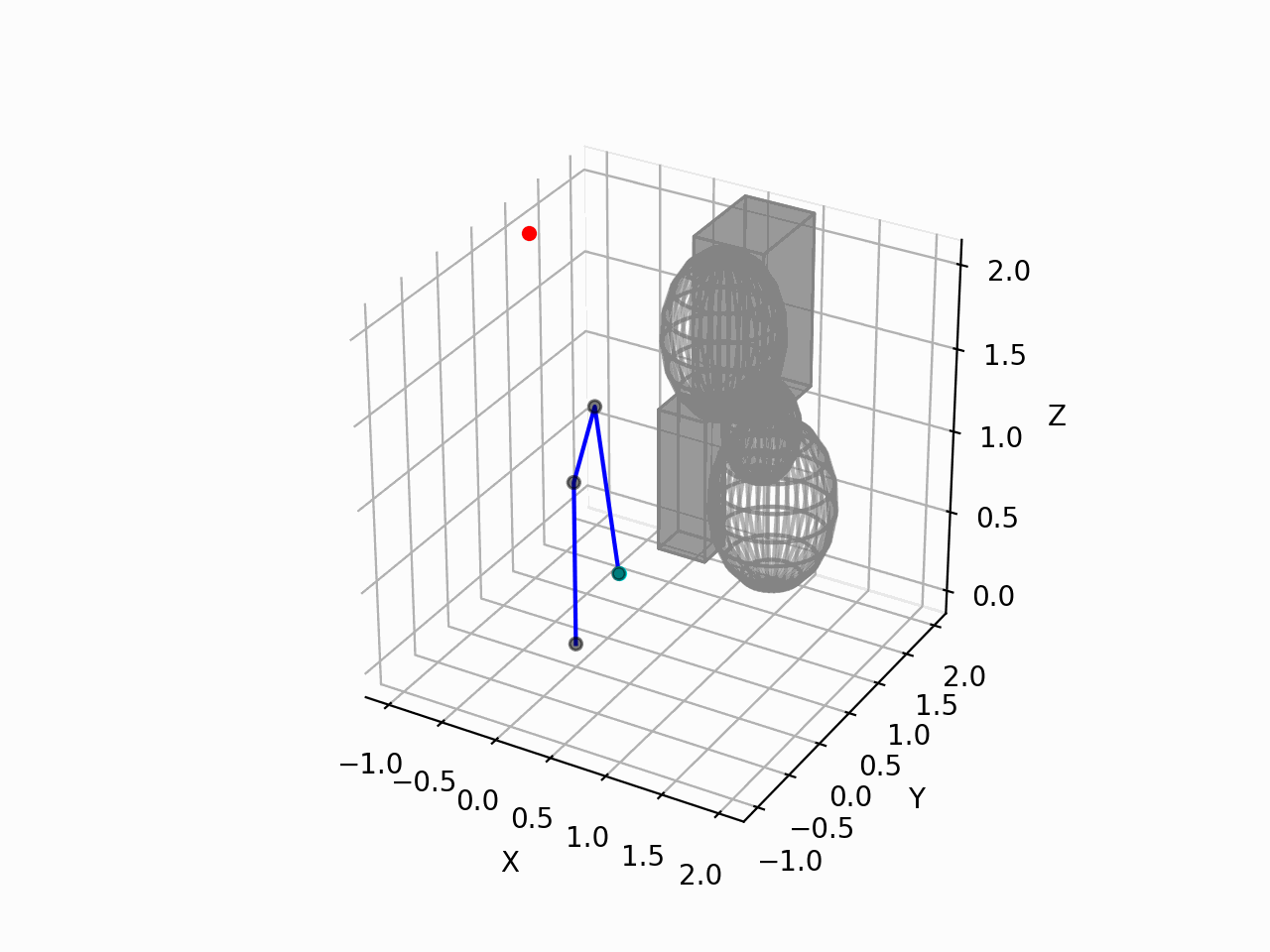
ロボットアームが干渉物と当たらないような経路を生成することが確認できた.
しかしながら,生成した経路は最短な経路でない.
今回は,関節空間よりも,位置空間を探索した方が,最短な経路となった.RRTで探索する範囲をうまく調整すれば関節空間でも短い経路となるかもしれない.
今回は経路生成手法に RRT を採用しているが,RRT 以外の経路生成を使用すると,最短な経路になると思われる.
今回は3軸ロボットアームであったが,6軸ロボットアームでの経路生成を実行したい.
おわりに
本記事では,Pythonを使用して,下記内容を実装しました.
・干渉物が存在する環境下で,3軸ロボットアームの経路生成 + アニメーション
次記事では,下記内容を実装していきます.
・6軸ロボットアームの順運動学
(https://qiita.com/haruhiro1020/items/a240f8c8e538e75473a3)
・ロボットの手先位置・姿勢を算出するための同時変換行列
(https://qiita.com/haruhiro1020/items/424f5d38861c32038636)
・2軸ロボットアーム微分逆運動学