はじめに
私がロボットに関して興味を持っている.特にロボットの経路生成に興味がある.
前記事では,同時変換行列を使用して,2軸ロボットアームと3軸ロボットアームの順運動学を実装した.
(https://qiita.com/haruhiro1020/items/424f5d38861c32038636)
本記事では,6軸ロボットアームの順運動学を説明する.
順運動学とは,関節角度から手先位置を計算することです.
手先位置を算出するために,三角関数(sin, cos, tan)を使用する.以下サイトはわかりやすいです.
・https://www.meikogijuku.jp/meiko-plus/study/trigonometric-function.html
本記事で実装すること
・同時変換行列を使用して,6軸ロボットアームの順運動学を算出する.
本記事では実装できないこと (将来実装したい内容)
・6軸ロボットアームの逆運動学
動作環境
・macOS Sequoia (バージョン15.5)
・Python3 (3.10.9)
・Numpy (1.23.5) (数値計算用ライブラリ)
・Matplotlib (3.7.0) (アニメーション作成用ライブラリ)
6軸ロボットアームの順運動学
6軸ロボットアームの順運動学を実施する.
今回は下図のような6軸ロボットアームを考える.
関節$1$はz軸周りに$\theta_{1}$で回転し,関節$2$はy軸周りに$\theta_{2}$で回転し,関節$3$はy軸周りに$\theta_{3}$で回転し,関節$4$はz軸周りに$\theta_{4}$で回転し,関節$5$はy軸周りに$\theta_{5}$で回転し,関節$6$はz軸周りに$\theta_{6}$で回転する.

関節$1$ ~ $6$全部が角度$0[rad]$の時は,下図のようになる6軸ロボットアームを考える.
(全関節の座標系がワールド座標系と同じになる)

ワールド座標系から見た関節6の同時変換行列を算出
ワールド座標系から見た関節6の同時変換行列を算出する.
同時変換行列を算出するための準備をする.
今回,関節$1$,$4$,$6$はz軸周りに回転し,関節$2$,$3$,$5$はy軸周りに回転するため,回転行列は下式の通りとなる.
\displaylines{

{}^{w}R_{1}
=
\begin{pmatrix}
\cos\theta_{1} & -\sin\theta_{1} & 0 \\
\sin\theta_{1} &  \cos\theta_{1} & 0 \\
0              &  0              & 1 \\
\end{pmatrix} ,

{}^{1}R_{2}
=
\begin{pmatrix}
 \cos\theta_{2} & 0 & \sin\theta_{2} \\
 0              & 1 & 0              \\
-\sin\theta_{2} & 0 & \cos\theta_{2} \\
\end{pmatrix} \\

{}^{2}R_{3}
=
\begin{pmatrix}
 \cos\theta_{3} & 0 & \sin\theta_{3} \\
 0              & 1 & 0              \\
-\sin\theta_{3} & 0 & \cos\theta_{3} \\
\end{pmatrix} ,

{}^{3}R_{4}
=
\begin{pmatrix}
\cos\theta_{4} & -\sin\theta_{4} & 0 \\
\sin\theta_{4} &  \cos\theta_{4} & 0 \\
0              &  0              & 1 \\
\end{pmatrix} \\

{}^{4}R_{5}
=
\begin{pmatrix}
 \cos\theta_{5} & 0 & \sin\theta_{5} \\
 0              & 1 & 0              \\
-\sin\theta_{5} & 0 & \cos\theta_{5} \\
\end{pmatrix} ,

{}^{5}R_{6}
=
\begin{pmatrix}
\cos\theta_{6} & -\sin\theta_{6} & 0 \\
\sin\theta_{6} &  \cos\theta_{6} & 0 \\
0              &  0              & 1 \\
\end{pmatrix} \\
}
各座標系の相対位置は下式の通りとなる.
\displaylines{

{}^{w}p_{1}
=
\begin{pmatrix}
0 \\
0 \\
0 \\
\end{pmatrix} ,

{}^{1}p_{2}
=
\begin{pmatrix}
0 \\
0 \\
l_{1} \\
\end{pmatrix} ,

{}^{2}p_{3}
=
\begin{pmatrix}
0 \\
0 \\
l_{2} \\
\end{pmatrix} \\

{}^{3}p_{4}
=
\begin{pmatrix}
0 \\
0 \\
l_{3} \\
\end{pmatrix} ,

{}^{4}p_{5}
=
\begin{pmatrix}
0 \\
0 \\
l_{4} \\
\end{pmatrix} ,

{}^{5}p_{6}
=
\begin{pmatrix}
0 \\
0 \\
l_{5} \\
\end{pmatrix} ,

{}^{6}p_{e}
=
\begin{pmatrix}
0 \\
0 \\
l_{6} \\
\end{pmatrix} \\

}
各座標系の同時変換行列を計算してみる.
\displaylines{

{}^{w}T_{1}
=
\begin{pmatrix}
{}^{w}R_{1} & {}^{w}p_{1} \\
0 & 1 \\
\end{pmatrix}
=
\begin{pmatrix}
\cos\theta_{1} & -\sin\theta_{1} & 0 & 0 \\
\sin\theta_{1} &  \cos\theta_{1} & 0 & 0 \\
0              &  0              & 1 & 0 \\
0              &  0              & 0 & 1 \\
\end{pmatrix} \\

{}^{1}T_{2}
=
\begin{pmatrix}
{}^{1}R_{2} & {}^{1}p_{2} \\
0 & 1 \\
\end{pmatrix}
=
\begin{pmatrix}
 \cos\theta_{2} & 0 & \sin\theta_{2} & 0 \\
 0              & 1 & 0              & 0 \\
-\sin\theta_{2} & 0 & \cos\theta_{2} & l_{1} \\
 0              & 0 & 0              & 1 \\
\end{pmatrix} \\

{}^{2}T_{3}
=
\begin{pmatrix}
{}^{2}R_{3} & {}^{2}p_{3} \\
0 & 1 \\
\end{pmatrix}
=
\begin{pmatrix}
 \cos\theta_{3} & 0 & \sin\theta_{3} & 0 \\
 0              & 1 & 0              & 0 \\
-\sin\theta_{3} & 0 & \cos\theta_{3} & l_{2} \\
 0              & 0 & 0              & 1 \\
\end{pmatrix} \\

{}^{3}T_{4}
=
\begin{pmatrix}
{}^{3}R_{4} & {}^{3}p_{4} \\
0 & 1 \\
\end{pmatrix}
=
\begin{pmatrix}
\cos\theta_{4} & -\sin\theta_{4} & 0 & 0 \\
\sin\theta_{4} &  \cos\theta_{4} & 0 & 0 \\
0              &  0              & 1 & l_{3} \\
0              &  0              & 0 & 1 \\
\end{pmatrix} \\

{}^{4}T_{5}
=
\begin{pmatrix}
{}^{4}R_{5} & {}^{4}p_{5} \\
0 & 1 \\
\end{pmatrix}
=
\begin{pmatrix}
 \cos\theta_{5} & 0 & \sin\theta_{5} & 0 \\
 0              & 1 & 0              & 0 \\
-\sin\theta_{5} & 0 & \cos\theta_{5} & l_{4} \\
 0              & 0 & 0              & 1 \\
\end{pmatrix} \\

{}^{5}T_{6}
=
\begin{pmatrix}
{}^{5}R_{6} & {}^{5}p_{6} \\
0 & 1 \\
\end{pmatrix}
=
\begin{pmatrix}
\cos\theta_{6} & -\sin\theta_{6} & 0 & 0 \\
\sin\theta_{6} &  \cos\theta_{6} & 0 & 0 \\
0              &  0              & 1 & l_{5} \\
0              &  0              & 0 & 1 \\
\end{pmatrix} \\

}
同時変換行列の掛け合わせにより,ワールド座標系から見たリンク6の同時変換行列を算出する.
\displaylines{
{}^{w}T_{6} = {}^{w}T_{1} * {}^{1}T_{2} * {}^{2}T_{3} * {}^{3}T_{4} * {}^{4}T_{5} * {}^{5}T_{6} \\
}
ロボットの手先位置を算出
同時変換行列より,ロボットの手先位置を算出する.
ワールド座標系から見たロボット手先位置を,上記で算出した同時変換行列を使用して算出する.
\displaylines{
{}^{w}\tilde P_{e} = {}^{w}T_{6} * {}^{6}\tilde P_{e} \\
{}^{6}\tilde P_{e}
=
\begin{pmatrix}
0 \\
0 \\
l_{6} \\
1 \\
\end{pmatrix} \\

{}^{w}\tilde P_{e}
=
\begin{pmatrix}
{}^{w}P_{e, x} \\
{}^{w}P_{e, y} \\
{}^{w}P_{e, z} \\
1 \\
\end{pmatrix} \\
}
ロボットの手先姿勢を算出
同時変換行列より,ロボットの手先姿勢を算出する.
ワールド座標系から見たロボット手先姿勢を,上記で算出した同時変換行列を使用して算出する.
\displaylines{
{}^{w}\tilde R_{e} = {}^{w}T_{6} * {}^{6}\tilde R_{e} \\
ロボット手先姿勢は関節6と同じ姿勢であるから,\\
{}^{6}\tilde R_{e}
=
\begin{pmatrix}
1 & 0 & 0 & 0 \\
0 & 1 & 0 & 0 \\
0 & 0 & 1 & 0 \\
0 & 0 & 0 & 1 \\
\end{pmatrix} \\

{}^{w}\tilde R_{e}
=
\begin{pmatrix}
{}^{w}R_{e} & 0 \\
0 & 1 \\
\end{pmatrix} \\

ロボット手先姿勢は関節6と同じ姿勢であるから,以下として簡単に表せれる.\\
{}^{w}R_{e} = {}^{w}R_{6} \\
{}^{w}T_{6}
=
\begin{pmatrix}
{}^{w}R_{6} & {}^{w}p_{6} \\
0 & 1 \\
\end{pmatrix} \\
{}^{w}R_{e}は{}^{w}T_{6}の回転行列成分である.\\
}
同時変換行列を使用することで,ロボットの手先位置・姿勢を算出することが可能となる.
手先姿勢は回転行列の3 * 3行列で表すことができる.
ただ,9個(3 * 3)のパラメータを保持していても直感的にどの軸にどれくらい回転しているかがわかりにくい.
そのため,3個のパラメータで姿勢を表現できかつ直感的にわかりやすいZ-Y-Xオイラー角を採用する.
回転行列とオイラー角との関係性は下記を参考とした.
(https://qiita.com/aa_debdeb/items/3d02e28fb9ebfa357eaf)
Z-Y-Xオイラー角の回転行列
Z-Y-Xオイラー角の回転行列は下式の通りとなる.
\displaylines{

R_{z-y-x} = R_{z}(\theta_{1}) * R_{y}(\theta_{2}) * R_{x}(\theta_{3}) \\

R_{z}(\theta_{1}), R_{y}(\theta_{2}), R_{x}(\theta_{3})は下記の通りとなる. \\
R_{z}(\theta_{1})
=
\begin{pmatrix}
\cos\theta_{1} & -\sin\theta_{1} & 0 \\
\sin\theta_{1} &  \cos\theta_{1} & 0 \\
0              &  0              & 1 \\
\end{pmatrix} \\

R_{y}(\theta_{2})
=
\begin{pmatrix}
 \cos\theta_{2} & 0 & \sin\theta_{2} \\
 0              & 1 & 0 \\
-\sin\theta_{2} & 0 & \cos\theta_{2} \\
\end{pmatrix} \\

R_{x}(\theta_{3})
=
\begin{pmatrix}
1 & 0 & 0 \\
0 & \cos\theta_{3} & -\sin\theta_{3} \\
0 & \sin\theta_{3} &  \cos\theta_{3} \\
\end{pmatrix} \\

上記より,R_{z-y-x}は以下のようになる.\\
R_{z-y-x}
=
\begin{pmatrix}
 \cos\theta_{1} * \cos\theta_{2}
& -\sin\theta_{1} * \cos\theta_{3} + \cos\theta_{1} * \sin\theta_{2} * \sin\theta_{3}
&  \sin\theta_{1} * \sin\theta_{3} + \cos\theta_{1} * \sin\theta_{2} * \cos\theta_{3} \\

 \sin\theta_{1} * \cos\theta_{2}
&  \cos\theta_{1} * \cos\theta_{3} + \sin\theta_{1} * \sin\theta_{2} * \sin\theta_{3}
& -\cos\theta_{1} * \sin\theta_{3} + \sin\theta_{1} * \sin\theta_{2} * \cos\theta_{3} \\

-\sin\theta_{2}
& \cos\theta_{2} * \sin\theta_{3}
& \cos\theta_{2} * \cos\theta_{3} \\
\end{pmatrix} \\
}
回転行列からZ-Y-Xオイラー角への変換
回転行列からZ-Y-Xオイラー角の変換は下式の通りとなる.
\displaylines{

R_{z-y-x}
=
\begin{pmatrix}
 \cos\theta_{1} * \cos\theta_{2}
& -\sin\theta_{1} * \cos\theta_{3} + \cos\theta_{1} * \sin\theta_{2} * \sin\theta_{3}
&  \sin\theta_{1} * \sin\theta_{3} + \cos\theta_{1} * \sin\theta_{2} * \cos\theta_{3} \\

 \sin\theta_{1} * \cos\theta_{2}
&  \cos\theta_{1} * \cos\theta_{3} + \sin\theta_{1} * \sin\theta_{2} * \sin\theta_{3}
& -\cos\theta_{1} * \sin\theta_{3} + \sin\theta_{1} * \sin\theta_{2} * \cos\theta_{3} \\

-\sin\theta_{2}
& \cos\theta_{2} * \sin\theta_{3}
& \cos\theta_{2} * \cos\theta_{3} \\
\end{pmatrix} \\ ... ①

R_{z-y-x}を以下のように置き換える\\
R_{z-y-x}
=
\begin{pmatrix}
r11 & r12 & r13 \\
r21 & r22 & r23 \\
r31 & r32 & r33 \\
\end{pmatrix} \\ ... ②
}
theta2の計算
①と②よりはじめに,$theta_{2}$を計算する.
\displaylines{
r31 = -\sin\theta_{2}より \\
\sin\theta_{2} = -r31 \\
r32^2 + r33^2 = \cos^2\theta_{2} * \sin^2\theta_{3} + \cos^2\theta_{2} * \cos^2\theta_{3} \\
r32^2 + r33^2 = \cos^2\theta_{2}より \\
\cos\theta_{2} = +-\sqrt(r32^2 + r33^2) \\
\sin\theta_{2}と\cos\theta_{2}より,\theta_{2}を算出する \\
\theta_{2} = atan2(\sin\theta_{2}, \cos\theta_{2}) \\
\theta_{2} = atan2(-r31, +-\sqrt(r32^2 + r33^2)) \\
}
$\theta_{2}$が$+-\pi/2$の時に,ジンバルロック(特異点)となる.
そのため,$\theta_{2}$が$+-\pi/2$で場合分けする必要がある.
theta2が+-pi/2の時のtheta1とtheta3の計算
$theta_{2}$が$+-\pi/2$の時の$theta_{1}$と$theta_{3}$の計算を説明する.
はじめに,$theta_{2}$が$+\pi/2$の時,①と②を使用して,下式のように計算できる.
\displaylines{
r13 = \sin\theta_{1} * \sin\theta_{3} + \cos\theta_{1} * \sin\theta_{2} * \cos\theta_{3} \\
\theta_{2}が\pi/2より,\sin\theta_{2} = 1となるため \\
r13 = \sin\theta_{1} * \sin\theta_{3} + \cos\theta_{1} * \cos\theta_{3} \\
三角関数の公式より \\
r13 = \cos(\theta_{1} - \theta_{3}) \\

r23 = -\cos\theta_{1} * \sin\theta_{3} + \sin\theta_{1} * \sin\theta_{2} * \cos\theta_{3} \\
\theta_{2}が\pi/2より,\sin\theta_{2} = 1となるため \\
r23 = -\cos\theta_{1} * \sin\theta_{3} + \sin\theta_{1} * \cos\theta_{3} \\
三角関数の公式より \\
r23 = \sin(\theta_{1} - \theta_{3}) \\

\theta_{1} - \theta_{3} = atan2(\sin(\theta_{1} - \theta_{3}), \cos(\theta_{1} - \theta_{3}) )より \\
\theta_{1} - \theta_{3} = atan2(r23, r13) \\

\theta_{1} = 0.0と固定すると \\
\theta_{3} = -atan2(r23, r13)となる \\

}
次に,$theta_{2}$が$-\pi/2$の時,①と②を使用して,下式のように計算できる.
\displaylines{
r13 = \sin\theta_{1} * \sin\theta_{3} + \cos\theta_{1} * \sin\theta_{2} * \cos\theta_{3} \\
\theta_{2}が-\pi/2より,\sin\theta_{2} = -1となるため \\
r13 = \sin\theta_{1} * \sin\theta_{3} - \cos\theta_{1} * \cos\theta_{3} \\
三角関数の公式より \\
r13 = -\cos(\theta_{1} + \theta_{3}) \\

r23 = -\cos\theta_{1} * \sin\theta_{3} + \sin\theta_{1} * \sin\theta_{2} * \cos\theta_{3} \\
\theta_{2}が-\pi/2より,\sin\theta_{2} = -1となるため \\
r23 = -\cos\theta_{1} * \sin\theta_{3} - \sin\theta_{1} * \cos\theta_{3} \\
三角関数の公式より \\
r23 = -\sin(\theta_{1} + \theta_{3}) \\

\theta_{1} + \theta_{3} = atan2(\sin(\theta_{1} + \theta_{3}), \cos(\theta_{1} + \theta_{3}) )より \\
\theta_{1} + \theta_{3} = atan2(-r23, -r13) \\

\theta_{1} = 0.0と固定すると \\
\theta_{3} = atan2(-r23, -r13)となる \\

}
特異点であっても,オイラー角を算出することは可能である.
ただ,今回は特異点時に$\theta_{1} = 0.0$固定としていることに注意しないといけない.
theta2が+-pi/2ではない時のtheta1とtheta3の計算
①と②より次に,$theta_{3}$を計算する.
\displaylines{
r32 = \cos\theta_{2} * \sin\theta_{3}より \\
\sin\theta_{3} = r32 / \cos\theta_{2} \\
r33 = \cos\theta_{2} * \cos\theta_{3}より \\
\cos\theta_{3} = r33 / \cos\theta_{2} \\
\sin\theta_{3}と\cos\theta_{3}より,\theta_{3}を算出する \\
\theta_{3} = atan2(\sin\theta_{3}, \cos\theta_{3}) \\
\theta_{3} = atan2(r32, r33) \\
}
①と②より最後に,$theta_{1}$を計算する.
\displaylines{
r11 = \cos\theta_{1} * \cos\theta_{2}より \\
\cos\theta_{1} = r11 / \cos\theta_{2} \\
r21 = \sin\theta_{1} * \cos\theta_{2}より \\
\sin\theta_{1} = r21 / \cos\theta_{2} \\
\sin\theta_{1}と\cos\theta_{1}より,\theta_{1}を算出する \\
\theta_{1} = atan2(\sin\theta_{1}, \cos\theta_{1}) \\
\theta_{1} = atan2(r21, r11) \\
}
以上より,回転行列からZ-Y-Xオイラー角への変換が可能となる.
順運動学のソースコード
定数を定義するファイル (constant.py)
定数を定義するファイルを下記に記載する.
# 複数ファイルで使用する定数の定義


# 次元数を定義
DIMENTION_NONE  = -1    # 未定義
DIMENTION_2D    =  2    # 2次元
DIMENTION_3D    =  3    # 3次元
DIMENTION_6D    =  6    # 3次元

# 回転軸
ROTATION_X_AXIS = "rot_x"   # x軸周りに回転
ROTATION_Y_AXIS = "rot_y"   # y軸周りに回転
ROTATION_Z_AXIS = "rot_z"   # z軸周りに回転
ROTATION_X_NEGATIVE_AXIS = "rot_neg_x"  # x軸周りに逆回転
ROTATION_Y_NEGATIVE_AXIS = "rot_neg_y"  # y軸周りに逆回転
ROTATION_Z_NEGATIVE_AXIS = "rot_neg_z"  # z軸周りに逆回転

# 0割を防ぐための定数
EPSILON                   = 1e-6
回転行列を定義するファイル (rotation.py)
回転行列を定義するファイルを下記に記載する.
# 回転行列の定義

# 標準ライブラリの読み込み
import numpy as np


# サードパーティーの読み込み


# 自作モジュールの読み込み
from constant import *      # 定数


class MyRotation:
    """
    回転行列クラス
    """
    _PITCH_THRESHOLD = 1e-4             # ピッチ角の閾値
    _ZERO_NEAR = 1e-4                   # 0近傍の閾値
    _EPSILON   = 1e-5                   # 微小値

    _ROT_MAX_VALUE =  1.0           # 回転行列の最大値
    _ROT_MIN_VALUE = -1.0           # 回転行列の最小値


    def _rot_x(self, theta):
        """
        x軸方向にtheta[rad]回転させる回転行列

        パラメータ
            theta(float): 回転角度 [rad]

        戻り値
            rotation(numpy.ndarray): 回転行列
        """
        rotation = np.array([[1, 0,              0            ],
                             [0, np.cos(theta), -np.sin(theta)],
                             [0, np.sin(theta),  np.cos(theta)]])

        return rotation

    def _rot_y(self, theta):
        """
        y軸方向にtheta[rad]回転させる回転行列

        パラメータ
            theta(float): 回転角度 [rad]

        戻り値
            rotation(numpy.ndarray): 回転行列
        """
        rotation = np.array([[ np.cos(theta), 0, np.sin(theta)],
                             [ 0,             1, 0            ],
                             [-np.sin(theta), 0, np.cos(theta)]])

        return rotation

    def _rot_z(self, theta):
        """
        z軸方向にtheta[rad]回転させる回転行列

        パラメータ
            theta(float): 回転角度 [rad]

        戻り値
            rotation(numpy.ndarray): 回転行列
        """
        rotation = np.array([[np.cos(theta), -np.sin(theta), 0],
                             [np.sin(theta),  np.cos(theta), 0],
                             [0,              0,             1]])

        return rotation

    def rot(self, theta, axis):
        """
        回転軸に応じた回転行列の取得

        パラメータ
            theta(float): 回転角度 [rad]
            axis(str): 回転軸

        戻り値
            rotation(numpy.ndarray): 回転行列
        """
        if axis == ROTATION_X_AXIS:
            # 回転軸がx軸
            rotation = self._rot_x(theta)
        elif axis == ROTATION_Y_AXIS:
            # 回転軸がy軸
            rotation = self._rot_y(theta)
        elif axis == ROTATION_Z_AXIS:
            # 回転軸がz軸
            rotation = self._rot_z(theta)
        elif axis == ROTATION_X_NEGATIVE_AXIS:
            # 回転軸がx軸だが,逆回転
            rotation = self._rot_x(-theta)
        elif axis == ROTATION_Y_NEGATIVE_AXIS:
            # 回転軸がy軸だが,逆回転
            rotation = self._rot_y(-theta)
        elif axis == ROTATION_Z_NEGATIVE_AXIS:
            # 回転軸がz軸だが,逆回転
            rotation = self._rot_z(-theta)
        else:
            # 異常
            raise ValueError(f"axis is abnormal. now is {axis}")

        return rotation

    def rot_from_zyx_euler(self, euler):
        """
        Z(theta1)-Y(theta2)-X(theta3)オイラー角による回転行列の計算

        パラメータ
            euler(float): Z(theta1)-Y(theta2)-X(theta3)オイラー角 [rad]

        戻り値
            rotation(numpy.ndarray): 回転行列
        """
        # 引数を分解する
        theta1 = euler[0]
        theta2 = euler[1]
        theta3 = euler[2]

        # 回転行列を計算
        rot_z  = self._rot_z(theta1)
        rot_y  = self._rot_y(theta2)
        rot_x  = self._rot_x(theta3)

        # Z-Y-X軸に順番に回転させた時の回転行列を計算
        rotation = np.dot(rot_z, rot_y)
        rotation = np.dot(rotation, rot_x)

        return rotation

    def rot_to_zyx_euler(self, rotation, y_cos_plus=True):
        """
        回転行列からZ(theta1)-Y(theta2)-X(theta3)オイラー角を取得

        パラメータ
            rotation(numpy.ndarray): 回転行列
            y_cos_plus(bool): Y(theta2)を+にするか

        戻り値
            zyx_euler(numpy.ndarray): Z(theta1)-Y(theta2)-X(theta3)オイラー角 [rad] の順番にデータを保存
        """
        # 引数の確認
        if rotation.shape != (3, 3):
            # 回転行列ではない
            raise ValueError(f"rotation's shape is abnormal. rotaton'shape is {rotation.shape}")

        # 回転行列の要素を一度,ローカル変数に保存
        # r11 =  cos(theta1) * cos(theta2)
        # r12 = -sin(theta1) * cos(theta3) + cos(theta1) * sin(theta2) * sin(theta3)
        # r13 =  sin(theta1) * sin(theta3) + cos(theta1) * sin(theta2) * cos(theta3)
        r11, r12, r13 = rotation[0, :]

        # r21 =  sin(theta1) * cos(theta2)
        # r22 =  cos(theta1) * cos(theta3) + sin(theta1) * sin(theta2) * sin(theta3)
        # r23 = -cos(theta1) * sin(theta3) + sin(theta1) * sin(theta2) * cos(theta3)
        r21, r22, r23 = rotation[1, :]

        # r31 = -sin(theta2)
        # r32 =  cos(theta2) * sin(theta3)
        # r33 =  cos(theta2) * cos(theta3)
        r31, r32, r33 = rotation[2, :]

        # はじめにtheta2から求める
        # r32 ** 2 + r33 * 2 = cos^2(theta2)
        # r31 = -sin(theta2)
        # theta2 = np.atan2(sin(theta2), cos(theta2)) = np.atan2(-r31, root(r32 ** 2 + r33 ** 2))
        theta2_sin = -r31
        if y_cos_plus:
            theta2_cos =  np.sqrt(r32 ** 2 + r33 ** 2)
        else:
            theta2_cos = -np.sqrt(r32 ** 2 + r33 ** 2)
        theta2 = np.arctan2(theta2_sin, theta2_cos)

        if abs(theta2 - np.pi / 2) <= self._PITCH_THRESHOLD:
            # theta2がpi/2付近では特異点となる
            # cos(theta2) = 0でsin(theta2) = 1となる
            # r13 =  sin(theta1) * sin(theta3) + cos(theta1) * sin(theta2) * cos(theta3) =  sin(theta1) * sin(theta3) + cos(theta1) * cos(theta3) = cos(theta1 - theta3)
            # r23 = -cos(theta1) * sin(theta3) + sin(theta1) * sin(theta2) * cos(theta3) = -cos(theta1) * sin(theta3) + sin(theta1) * cos(theta3) = sin(theta1 - theta3)
            # theta1 - theta3 = np.atan2(sin(theta1 - theta3), cos(theta1 - theta3)) = np.atan2(r23, r13)
            # theta1 = 0とすると theta3 = -np.atan2(r23, r13)となる
            theta1 = 0.0
            theta3 = -np.arctan2(r23, r13)
        elif abs(theta2 + np.pi / 2) <= self._PITCH_THRESHOLD:
            # theta2が-pi/2付近では特異点となる
            # cos(theta2) = 0でsin(theta2) = -1となる
            # r13 =  sin(theta1) * sin(theta3) + cos(theta1) * sin(theta2) * cos(theta3) =  sin(theta1) * sin(theta3) - cos(theta1) * cos(theta3) = -cos(theta1 + theta3)
            # r23 = -cos(theta1) * sin(theta3) + sin(theta1) * sin(theta2) * cos(theta3) = -cos(theta1) * sin(theta3) - sin(theta1) * cos(theta3) = -sin(theta1 + theta3)
            # theta1 + theta3 = np.atan2(sin(theta1 + theta3), cos(theta1 + theta3)) = np.atan2(-r23, -r13)
            # theta1 = 0とすると theta3 = np.atan2(-r23, -r13)となる
            theta1 = 0.0
            theta3 = np.arctan2(-r23, -r13)
        else:
            # 特異点付近ではない場合
            # r21 = sin(theta1) * cos(theta2)
            # r11 = cos(theta1) * cos(theta2)
            # theta1 = np.atan2(sin(theta1), cos(theta1)) = np.atan2(r21/cos(theta2), r11/cos(theta2)) = np.atan2(r21, r11)
            theta1 = np.arctan2(r21, r11)

            # r32 = cos(theta2) * sin(theta3)
            # r33 = cos(theta2) * cos(theta3)
            # theta3 = np.atan2(sin(theta3), cos(theta3)) = np.atan2(r32/cos(theta2), r33/cos(theta2)) = np.atan2(r32, r33)
            theta3 = np.arctan2(r32, r33)

        # Z(theta1)-Y(theta2)-X(theta3)オイラー角の順番に保存
        euler = np.array([theta1, theta2, theta3])

        return euler
ロボットアームを定義するファイル (robot.py)
ロボットアームを定義するファイルを下記に記載する.
# ロボットアームの運動学を記載

# ライブラリの読み込み
import numpy as np

# サードパーティーの読み込み
import fcl

# 自作モジュールの読み込み
from constant import *              # 定数
from rotation import MyRotation       # 回転行列


class Robot:
    """
    ロボットのベースクラス(抽象クラス)

    プロパティ
        _links(numpy.ndarray): ロボットのリンク長 [m]
        _rot(Rotation): 回転行列クラス
        _objects(list): 干渉物オブジェクト
        _manager(fcl.DynamicAABBTreeCollisionManager): 干渉判定クラス

    メソッド
        public
            forward_kinematics(): 順運動学 (ロボットの関節角度からロボットの手先位置を算出)
            inverse_kinematics(): 逆運動学 (ロボットの手先位置からロボットの関節角度を算出)
            forward_kinematics_all_pos(): 順運動学で全リンクの位置を取得
            update(): 角度を与えて,各リンクの直方体を更新する
            links(): _linksプロパティのゲッター
            manager(): _managerプロパティのゲッター

        protected
            _calc_homogeneou_matrix(): 同時変換行列の計算
    """
    # 定数の定義
    _DIMENTION_POSE  = DIMENTION_NONE       # 手先位置の次元数
    _DIMENTION_THETA = DIMENTION_NONE       # 関節角度の次元数
    _DIMENTION_LINK  = DIMENTION_NONE       # リンク数
    _DIMENTION_AXIS  = DIMENTION_NONE       # 回転軸数

    _INITIAL_THETA   = 0.0                  # 初期回転角度 [rad]
    _HOMOGENEOU_MAT_ELEMENT = 4             # 同時変換行列の次元数
    _ROTATION_MAT_ELEMENT   = 3             # 回転行列の次元数


    def __init__(self, links):
        """
        コンストラクタ

        パラメータ
            links(numpy.ndarray): ロボットのリンク長 [m]
        """
        if np.size(links) != self._DIMENTION_LINK:
            # 異常
            raise ValueError(f"links's size is abnormal. correct is {self._DIMENTION_Link}")

        # プロパティの初期化
        self._links = links
        self._rot = MyRotation()
        self._objects = []
        self._manager = None

    @property
    def links(self):
        """
        _linksプロパティのゲッター
        """
        return self._links

    @property
    def manager(self):
        """
        _managerプロパティのゲッター
        """
        return self._manager

    def forward_kinematics(self, thetas):
        """
        順運動学 (ロボットの関節角度からロボットの手先位置を算出)

        パラメータ
            thetas(numpy.ndarray): ロボットの関節角度 [rad]

        戻り値
            pose(numpy.ndarray): ロボットの手先位置 (位置 + 姿勢) [m] + [rad]
        """
        raise NotImplementedError("forward_kinematics() is necessary override.")

    def inverse_kinematics(self, pose):
        """
        逆運動学 (ロボットの手先位置からロボットの関節角度を算出)

        パラメータ
            pose(numpy.ndarray): ロボットの手先位置 (位置 + 姿勢) [m] + [rad]

        戻り値
            thetas(numpy.ndarray): ロボットの関節角度 [rad]
        """
        raise NotImplementedError("inverse_kinematics() is necessary override.")

    def forward_kinematics_all_pos(self, thetas):
        """
        順運動学で全リンクの位置を取得

        パラメータ
            thetas(numpy.ndarray): ロボットの関節角度 [rad]

        戻り値
            all_pose(numpy.ndarray): ロボットの全リンク位置 (位置 + 姿勢) [m] + [rad]
        """
        raise NotImplementedError("forward_kinematics() is necessary override.")

    def update(self, thetas):
        """
        角度を与えて,各リンクの直方体を更新する

        パラメータ
            thetas(numpy.ndarray): ロボットの関節角度 [rad]
        """
        raise NotImplementedError("update() is necessary override.")

    def _calc_homogeneou_matrix(self, thetas):
        """
        同時変換行列の計算

        パラメータ
            thetas(numpy.ndarray): 関節角度 [rad]

        戻り値
            homogeneou_matix(numpy.ndarray): 全リンクの同時変換行列
        """
        # パラメータの次元数を確認
        if np.size(thetas) != self._DIMENTION_THETA:
            raise ValueError(f"thetas's size is abnormal. thetas's size is {np.size(thetas)}")

        homogeneou_matix = np.zeros((self._DIMENTION_LINK, self._HOMOGENEOU_MAT_ELEMENT, self._HOMOGENEOU_MAT_ELEMENT))

        # 1リンク前の同時変換行列
        prev_homogeneou_matrix = np.eye(self._HOMOGENEOU_MAT_ELEMENT)
        for i in range(self._DIMENTION_THETA):
            # 4行4列の要素を1に更新
            homogeneou_matix[i, -1, -1] = 1
            # 回転行列の計算
            rotation_matrix   = self._rot.rot(thetas[i], self._axiss[i])
            # リンク間の相対位置を取得
            relative_position = self._relative_positions[i].reshape(1, -1)
            # 同時変換行列に回転行列を保存
            homogeneou_matix[i, :self._ROTATION_MAT_ELEMENT, :self._ROTATION_MAT_ELEMENT] = rotation_matrix
            # 同時変換行列に相対位置を保存
            homogeneou_matix[i, :self._ROTATION_MAT_ELEMENT,  self._ROTATION_MAT_ELEMENT] = relative_position
            # 1リンク前の同時変換行列と組み合わせる
            homogeneou_matix[i] = np.dot(prev_homogeneou_matrix, homogeneou_matix[i])
            # 1リンク前の同時変換行列の更新
            prev_homogeneou_matrix = homogeneou_matix[i]

        return homogeneou_matix


class Robot6DoF(Robot):
    """
    6軸ロボットクラス

    プロパティ
        _links(numpy.ndarray): ロボットのリンク長
        _rot(Rotation): 回転行列クラス
        _axiss(list): 関節の回転軸

    メソッド
        public
            forward_kinematics(): 順運動学 (ロボットの関節角度からロボットの手先位置を算出)
            inverse_kinematics(): 逆運動学 (ロボットの手先位置からロボットの関節角度を算出)
            forward_kinematics_all_pos(): 順運動学で全リンクの位置を取得
            update(): 角度を与えて,各リンクの直方体を更新する
    """
    # 定数の定義
    _DIMENTION_POSE  = DIMENTION_6D         # 手先位置・姿勢の次元数
    _DIMENTION_THETA = DIMENTION_6D         # 関節角度の次元数
    _DIMENTION_LINK  = DIMENTION_6D         # リンク数

    _DETERMINANT_THRESHOLD = 1e-4           # 行列式の閾値
    _THETA1_XY_THRESHOLD   = 1e-4           # theta1算出時のx, y閾値
    _BOX_WIDTH = 1e-2                       # 各リンクの幅を定義


    def __init__(self, links):
        """
        コンストラクタ

        パラメータ
            links(numpy.ndarray): ロボットのリンク長 [m]
        """
        # 親クラスの初期化
        super().__init__(links)

        # (全リンクの角度を0とした時の) 各リンク間の相対位置
        self._relative_positions = np.zeros((self._DIMENTION_LINK + 1, 3))
        self._relative_positions[0] = np.array([0, 0, 0])
        self._relative_positions[1] = np.array([0, 0, self._links[0]])
        self._relative_positions[2] = np.array([0, 0, self._links[1]])
        self._relative_positions[3] = np.array([0, 0, self._links[2]])
        self._relative_positions[4] = np.array([0, 0, self._links[3]])
        self._relative_positions[5] = np.array([0, 0, self._links[4]])
        self._relative_positions[6] = np.array([0, 0, self._links[5]])

        # リンク1,リンク4,リンク6は回転軸がz軸,リンク2,リンク3,リンク5は回転軸がy軸である
        self._axiss = [ROTATION_Z_AXIS, ROTATION_Y_AXIS, ROTATION_Y_AXIS, ROTATION_Z_AXIS, ROTATION_Y_AXIS, ROTATION_Z_AXIS]

    def forward_kinematics(self, thetas):
        """
        順運動学 (ロボットの関節角度からロボットの手先位置を算出)

        パラメータ
            thetas(numpy.ndarray): ロボットの関節角度 [rad]

        戻り値
            pose(numpy.ndarray): ロボットの手先位置・姿勢(RPY) [m] / [rad]
        """
        # パラメータの次元数を確認
        if np.size(thetas) != self._DIMENTION_THETA:
            raise ValueError(f"thetas's size is abnormal. thetas's size is {np.size(thetas)}")

        # 同時変換行列(6 * 4 * 4)を計算する
        homogeneou_matrix = self._calc_homogeneou_matrix(thetas)

        # 最終リンクの同時変換行列(最終リンク座標の位置・姿勢)より,手先位置を計算する
        final_link_matrix = homogeneou_matrix[self._DIMENTION_LINK - 1]
        # 最終リンクから手先位置までの早退位置(4ベクトル)を定義
        relative_pos = np.ones(self._HOMOGENEOU_MAT_ELEMENT)
        relative_pos[:self._HOMOGENEOU_MAT_ELEMENT - 1] = self._relative_positions[-1]
        # 手先位置(x, y, z)・姿勢(Z-Y-Xオイラー角)を保存する
        pose = np.zeros(self._DIMENTION_POSE)
        # 手先位置(x, y, z)を保存
        pose[:DIMENTION_3D] = np.dot(final_link_matrix, relative_pos)[:DIMENTION_3D]
        # 最終リンクの回転行列からZ-Y-Xオイラー角を計算
        zyx_euler = self._rot.rot_to_zyx_euler(final_link_matrix[:self._ROTATION_MAT_ELEMENT, :self._ROTATION_MAT_ELEMENT])
        # 手先位置姿勢を保存(手先姿勢は最終リンクと同じ姿勢と仮定する)
        pose[DIMENTION_3D:] = zyx_euler

        return pose

    def forward_kinematics_all_link_pos(self, thetas):
        """
        順運動学で全リンクの位置を取得 (グラフの描画で使用する)

        パラメータ
            thetas(numpy.ndarray): ロボットの関節角度 [rad]

        戻り値
            all_link_pose(numpy.ndarray): ロボットの全リンク位置 (位置 + 姿勢) [m] + [rad]
        """
        # パラメータの次元数を確認
        if np.size(thetas) != self._DIMENTION_THETA:
            raise ValueError(f"thetas's size is abnormal. thetas's size is {np.size(thetas)}")

        # 同時変換行列(6 * 4 * 4)を計算する
        homogeneou_matix = self._calc_homogeneou_matrix(thetas)

        # 全リンクの座標系の原点を取得
        all_link_pose = np.zeros((self._DIMENTION_LINK + 1, self._DIMENTION_POSE))
        for i, matrix in enumerate(homogeneou_matix):
            # 同時変換行列から位置を取得
            all_link_pose[i, :DIMENTION_3D] = matrix[:self._ROTATION_MAT_ELEMENT, self._ROTATION_MAT_ELEMENT].reshape(1, -1)
            # 同時変換行列から回転行列を取得して,Z-Y-Xオイラー角に変換する
            zyx_euler = self._rot.rot_to_zyx_euler(matrix[:self._ROTATION_MAT_ELEMENT, :self._ROTATION_MAT_ELEMENT])
            all_link_pose[i, DIMENTION_3D:] = zyx_euler

        # 最後のリンクの座標
        # 最後のリンクの座標系の原点から,手先の位置を計算する
        pos = np.ones(self._HOMOGENEOU_MAT_ELEMENT)
        pos[:DIMENTION_3D] = self._relative_positions[-1]
        all_link_pose[-1, :DIMENTION_3D] = np.dot(homogeneou_matix[-1], pos)[:DIMENTION_3D].reshape(1, -1)
        # 手先姿勢は最終リンクの姿勢と一致していると考え,最終リンクの回転行列をZ-Y-Xオイラー角に変換する
        zyx_euler = self._rot.rot_to_zyx_euler(homogeneou_matix[-1, :self._ROTATION_MAT_ELEMENT, :self._ROTATION_MAT_ELEMENT])
        all_link_pose[-1, DIMENTION_3D:] = zyx_euler

        return all_link_pose
メイン処理を実施するファイル (main.py)
メイン処理を実施するファイルを下記に記載する.
# メイン処理

# ライブラリの読み込み
import numpy as np                  # 数値計算
import matplotlib.pyplot as plt     # 描画

# 自作モジュールの読み込み
from constant import *              # 定数
from robot import Robot6DoF         # ロボットクラス


LINE_WIDTH = 3                      # プロット時の線の太さ
GRAPH_FORWARD_FILE_NAME = "plot_6drob_forward_kinematics.png"


def forward(robot, thetas, axis, plot_flg=True, label=True):
    """
    順運動学

    パラメータ
        robot(Robot3DoF): ロボットクラス
        thetas(numpy.ndarray): 関節角度 [rad]
        axis(figure.add_subplot): 3次元の描画軸
        plot_flg(bool): 描画の有無 (True / False = 描画する / しない)
        label(bool): 描画時のラベルの有無

    戻り値
        pose(numpy.ndarray): 手先位置
    """
    # 順運動学により,位置を算出
    pose = robot.forward_kinematics(thetas)

    if plot_flg:
        plot(robot, thetas, axis, label=label)
    else:
        # print(f"forward theta = {thetas}")
        # print(f"forward pose  = {pose}")
        pass

    return pose


def inverse(robot, pose, axis, plot_flg=True, upper=True, label=True):
    """
    逆運動学

    パラメータ
        robot(Robot3DoF): ロボットクラス
        pose(numpy.ndarray): 手先位置 [m]
        axis(figure.add_subplot): 3次元の描画軸
        plot_flg(bool): 描画の有無 (True / False = 描画する / しない)
        upper(bool): 関節が上向きとするかどうか (True / False = Yes / No)
        label(bool): 描画時のラベルの有無

    戻り値
        thetas(list): 関節角度
    """
    # 順運動学により,位置を算出
    thetas = robot.inverse_kinematics(pose, upper=upper)
    if plot_flg:
        plot(robot, thetas, axis)
    else:
        # print(f"inverse pose  = {pose}")
        # print(f"inverse theta = {thetas}")
        pass

    return thetas


def main():
    """
    メイン処理
    """
    # 3軸ロボットのリンク長
    links = np.array([1.0, 1.0, 1.0, 0.1, 0.1, 0.1])
    # 3軸ロボットのインスタンスを作成
    robot = Robot6DoF(links)
    # プロット有無
    plot_flg = True
    # ラベル有無
    label = False

    # 順運動学で使用する関節角度 [deg] を定義
    deg_thetas = [0, 60]
    candidate = np.deg2rad(deg_thetas)
    all_thetas = np.array([[theta1, theta2, theta3, theta4, theta5, theta6] for theta1 in candidate for theta2 in candidate for theta3 in candidate for theta4 in candidate for theta5 in candidate for theta6 in candidate])

    # 3次元グラフの作成
    fig = plt.figure()
    axis = fig.add_subplot(111, projection="3d")

    # 順運動学
    file_name = GRAPH_FORWARD_FILE_NAME
    for thetas in all_thetas:
        pose = forward(robot, thetas, axis, plot_flg=plot_flg, label=label)
        print(f"thetas = {thetas}")
        print(f"pose = {pose}")
        print()

    if plot_flg:
        show(axis, file_name)


def show(axis, graph_file_name):
    """
    描画する

    パラメータ
        axis(figure.add_subplot): 3次元の描画軸
        graph_file_name(str): 描画ファイル名
    """
    # X軸,Y軸,Z軸の名称
    axis.set_xlabel("X [m]")
    axis.set_ylabel("Y [m]")
    axis.set_zlabel("Z [m]")

    axis.grid()
    axis.set_aspect("equal")
    plt.legend(fontsize=5, loc='center left', bbox_to_anchor=(0.8, .5))
    # # 凡例を見切れないようにするために,plt.tight_layout()
    plt.tight_layout()
    plt.savefig(graph_file_name)
    plt.show()


def plot(robot, thetas, axis, label=True):
    """
    ロボットをプロット (将来的にはクラス化する)

    パラメータ
        robot(Robot3DoF): ロボット
        thetas(numpy.ndarray): 回転角度
        axis(figure.add_subplot): 3次元の描画軸
        label(bool): 描画時のラベルの有無
    """
    # 全リンクの位置を算出
    all_link_pos = robot.forward_kinematics_all_link_pos(thetas)

    # 線プロット
    if label:
        axis.plot(all_link_pos[:, 0], all_link_pos[:, 1], all_link_pos[:, 2], linewidth=LINE_WIDTH, label=f"theta1={np.rad2deg(thetas[0]):.1f} [deg], theta2={np.rad2deg(thetas[1]):.1f} [deg], theta3={np.rad2deg(thetas[2]):.1f} [deg], theta4={np.rad2deg(thetas[3]):.1f} [deg], theta5={np.rad2deg(thetas[4]):.1f} [deg], theta6={np.rad2deg(thetas[5]):.1f} [deg]")
    else:
        axis.plot(all_link_pos[:, 0], all_link_pos[:, 1], all_link_pos[:, 2], linewidth=LINE_WIDTH)

    # 点プロット
    axis.scatter(all_link_pos[:, 0], all_link_pos[:, 1], all_link_pos[:, 2])


if __name__ == "__main__":
    # 本ファイルがメインで呼ばれた時の処理
    main()
順運動学の結果
上記のmain.pyを実行した時の結果を下図に示す.
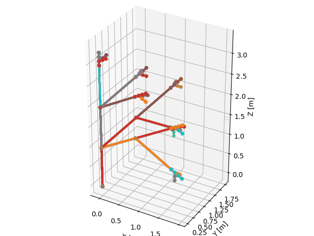
図を見る限りでは,順運動学が上手く実装できていると考えられる.
おわりに
本記事では,下記内容を実装しました.
・同時変換行列を使用して,6軸ロボットアームの順運動学
次記事では,下記内容を実装していきます.
・6軸ロボットアームの逆運動学
(https://qiita.com/haruhiro1020/items/af1d404b518aa6e13468)