このページ / About this page
このページはMini Pupperを動かそうの4/6ページです。
This is page 4 of How to get Mini Pupper walking.
工具 / Tools
キットに同梱されている工具の他に、組み立てには以下の物が必要です。
In addition to the tools included in the kit, the following items are required for assembly
- プラスドライバー / Screwdriver
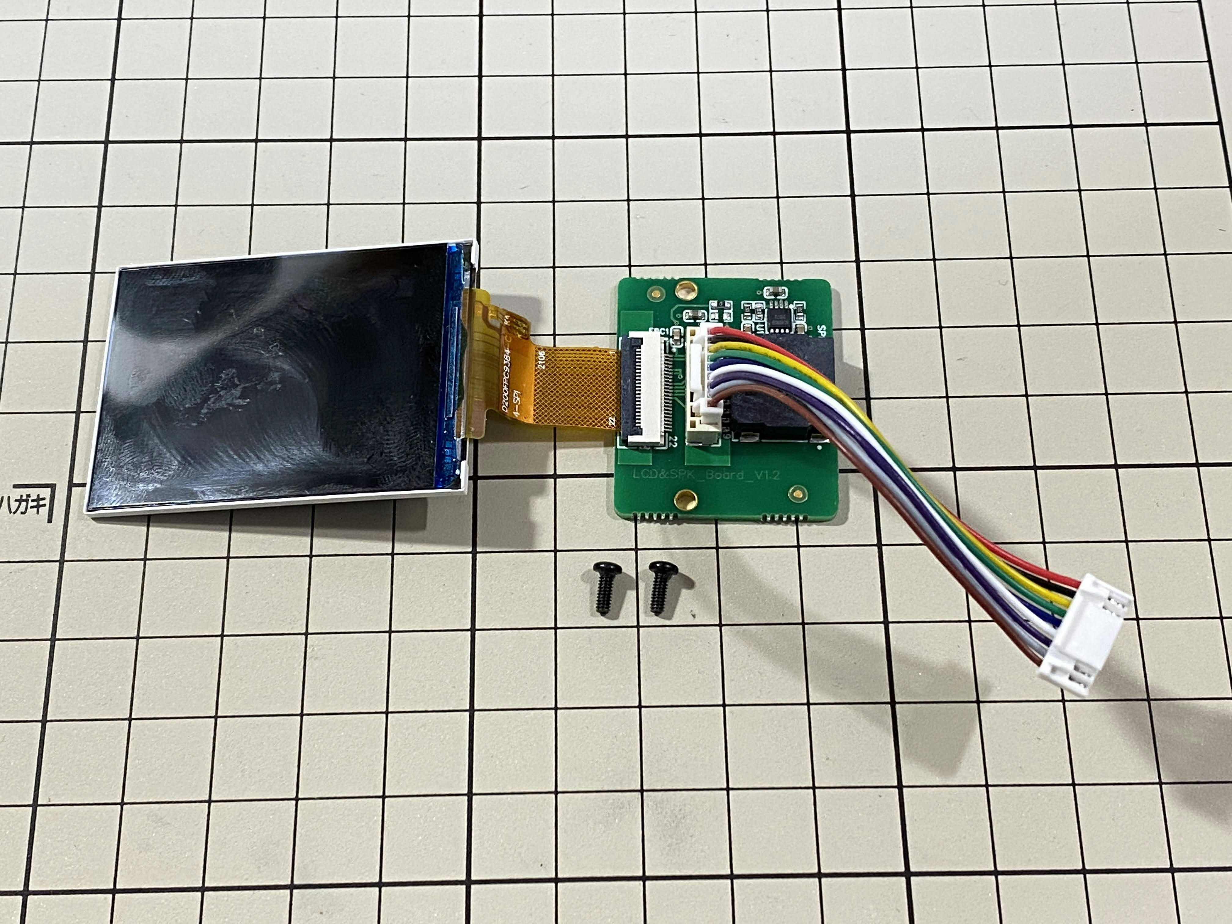
使用するボルト
(更新情報: Kickstarter版に合わせました)
| ボルト | 本数 | 使用箇所 |
|---|---|---|
| M2x5mm | 2 | 画面 |
| M1.4x3mm(皿) | 4 | 顔の枠 |
| M2x8mm | 2 | ファン |
機能コンポーネントの組み立て / Assemble the function component
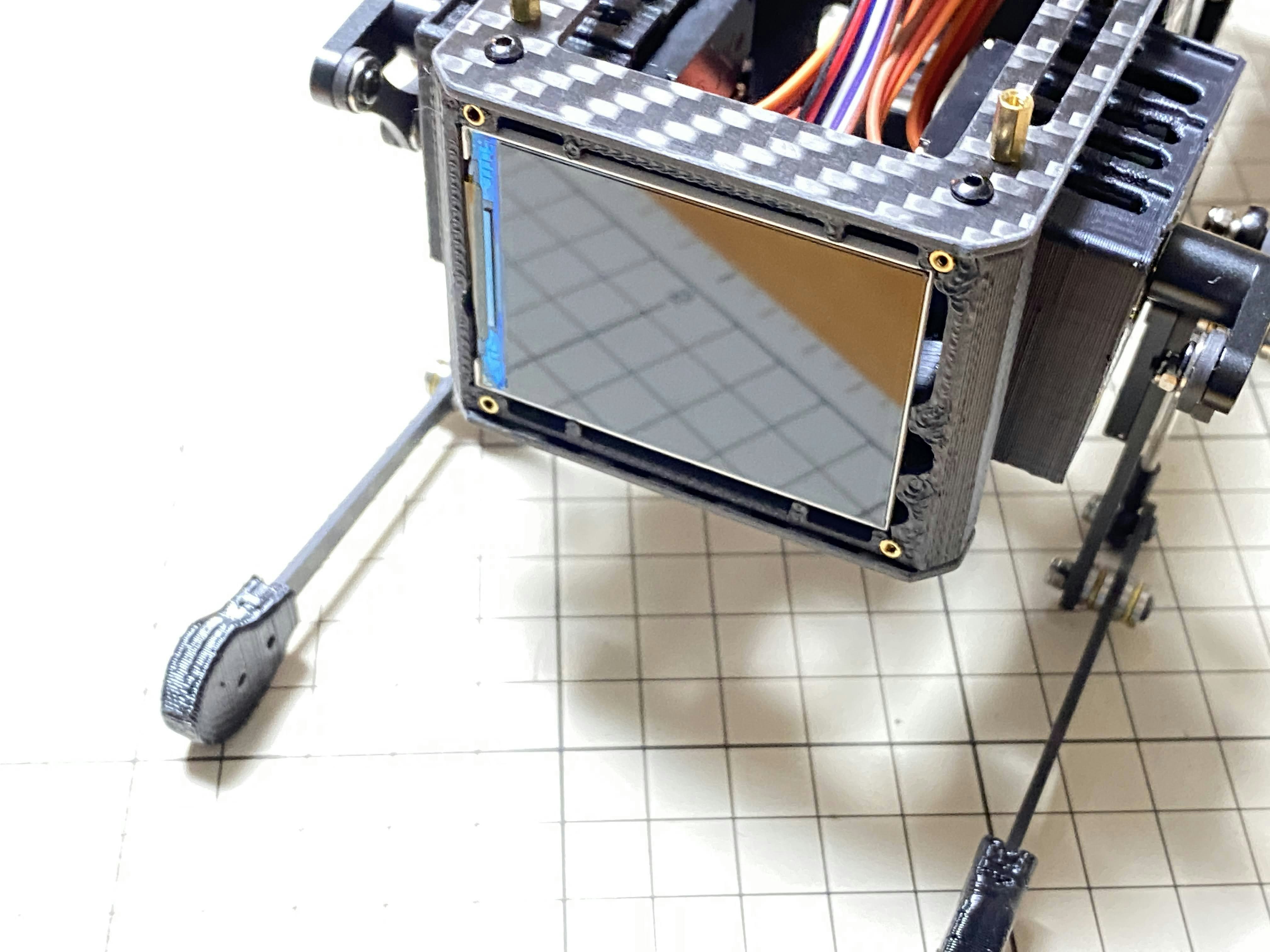
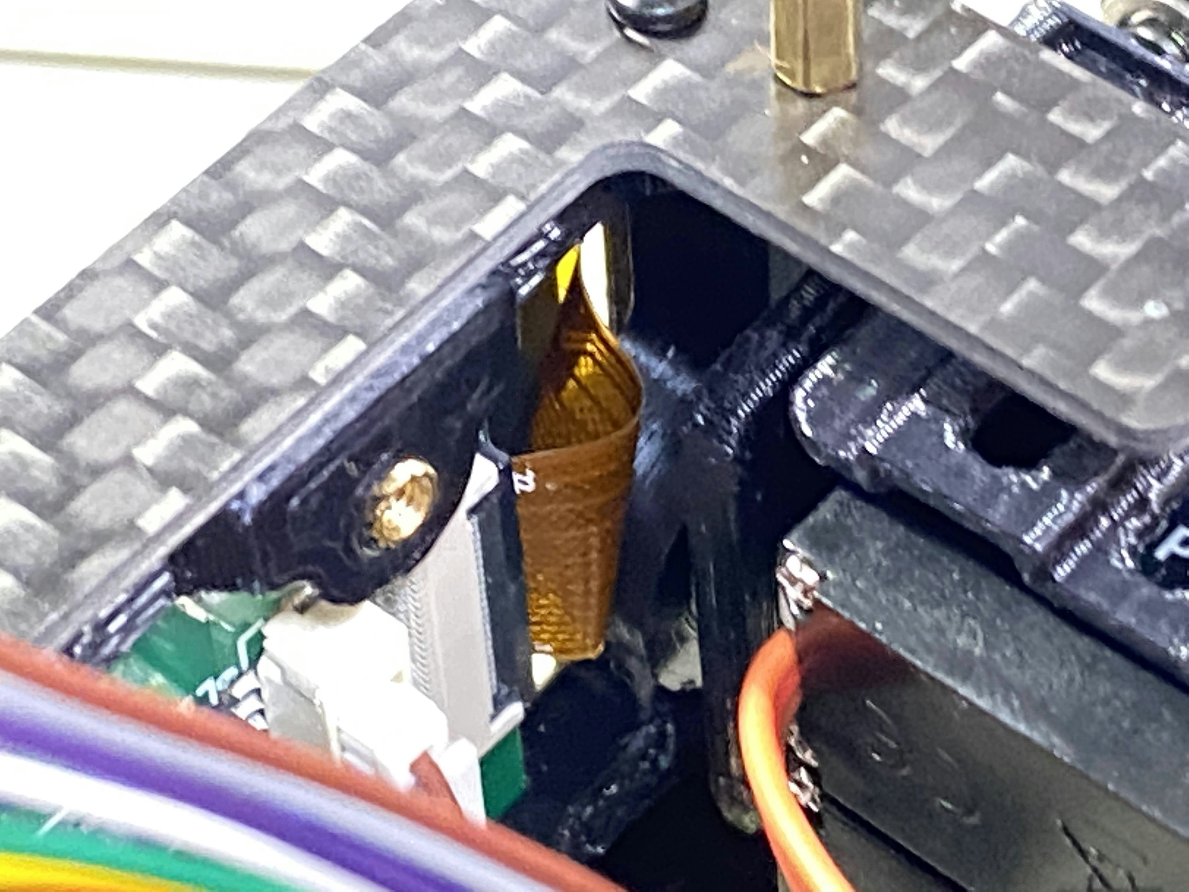
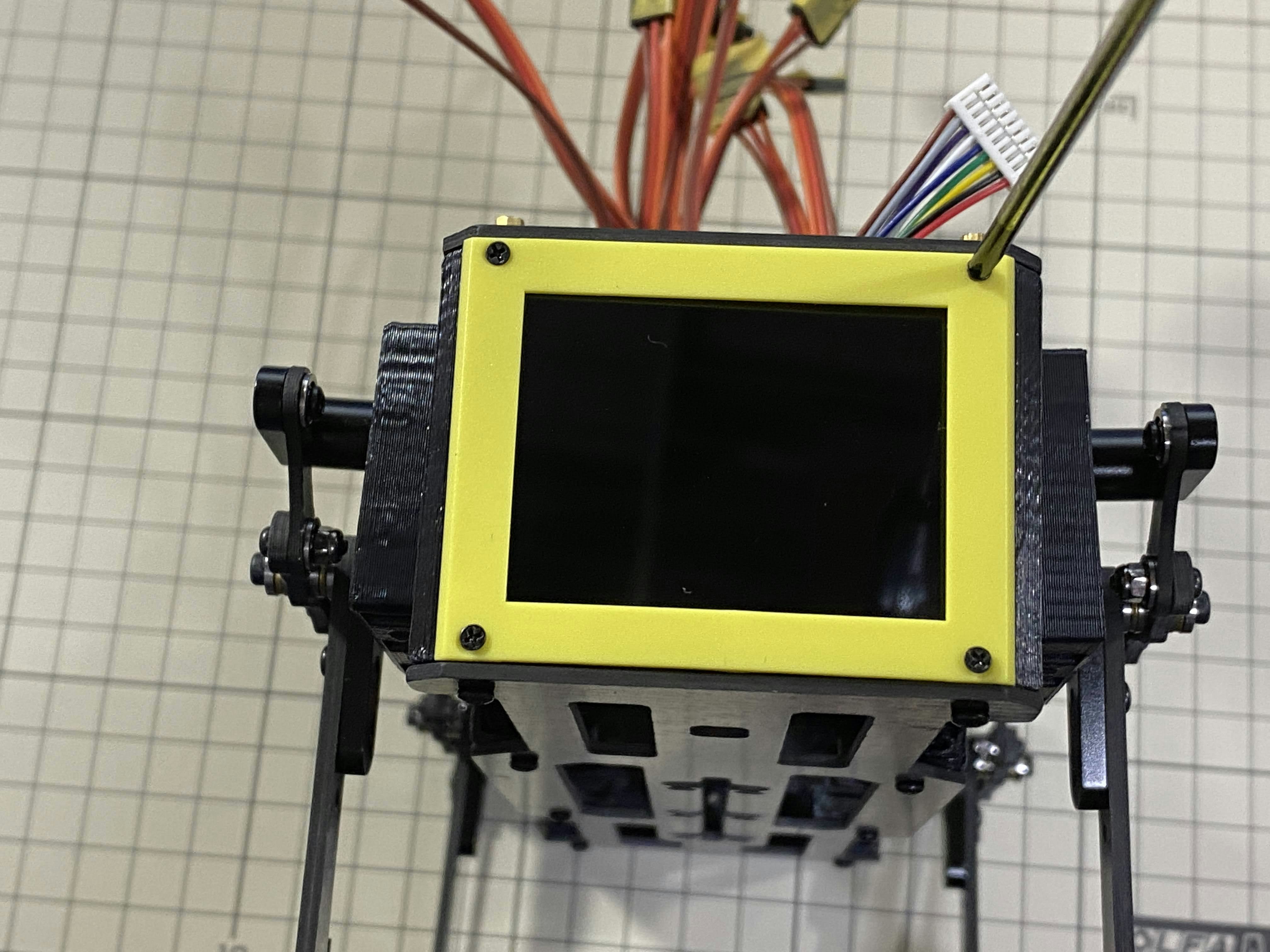
画面 / Display
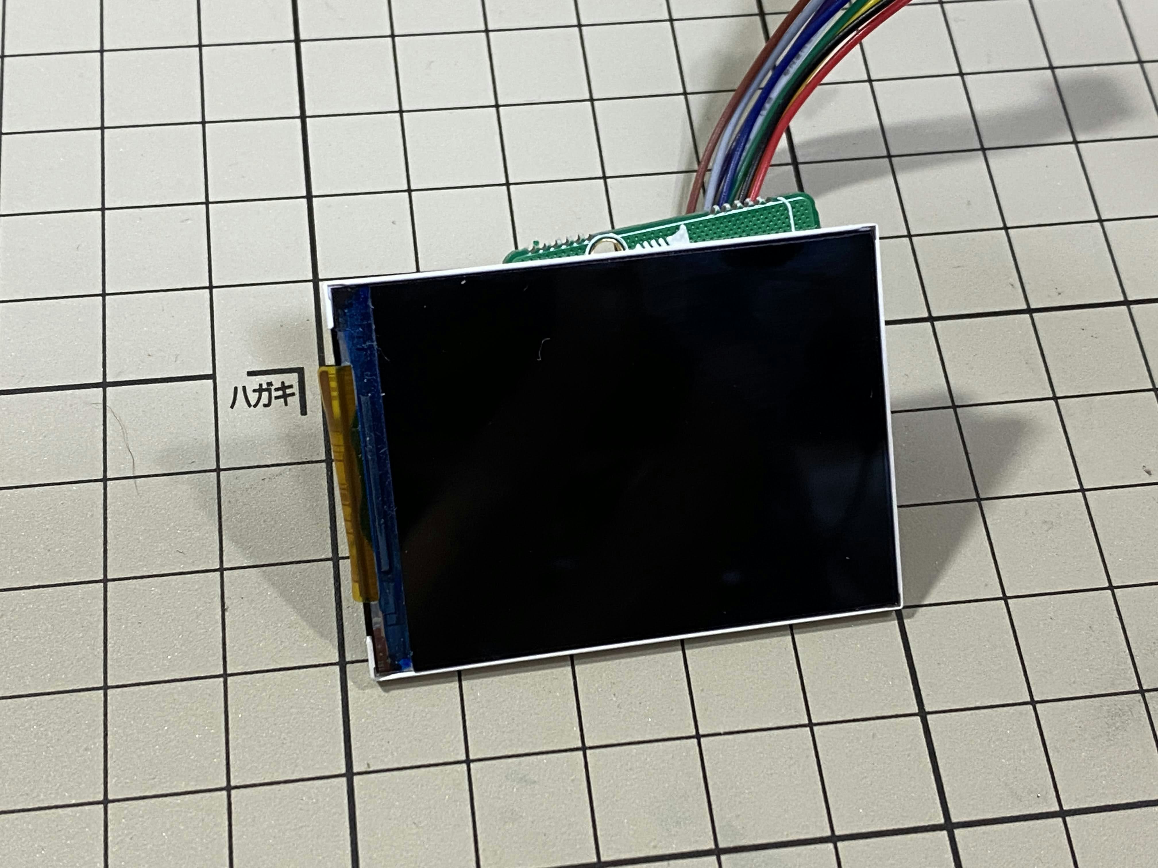
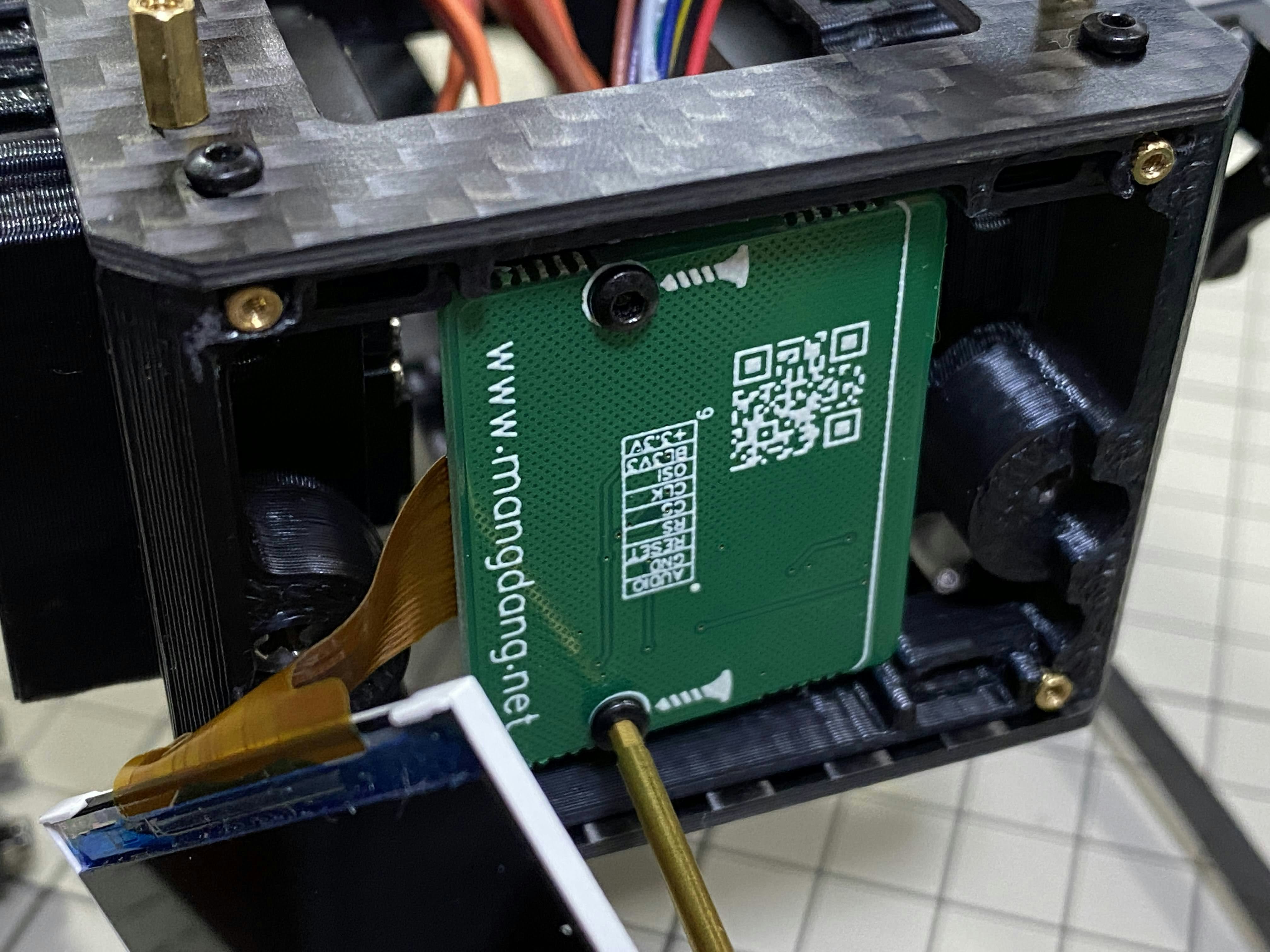
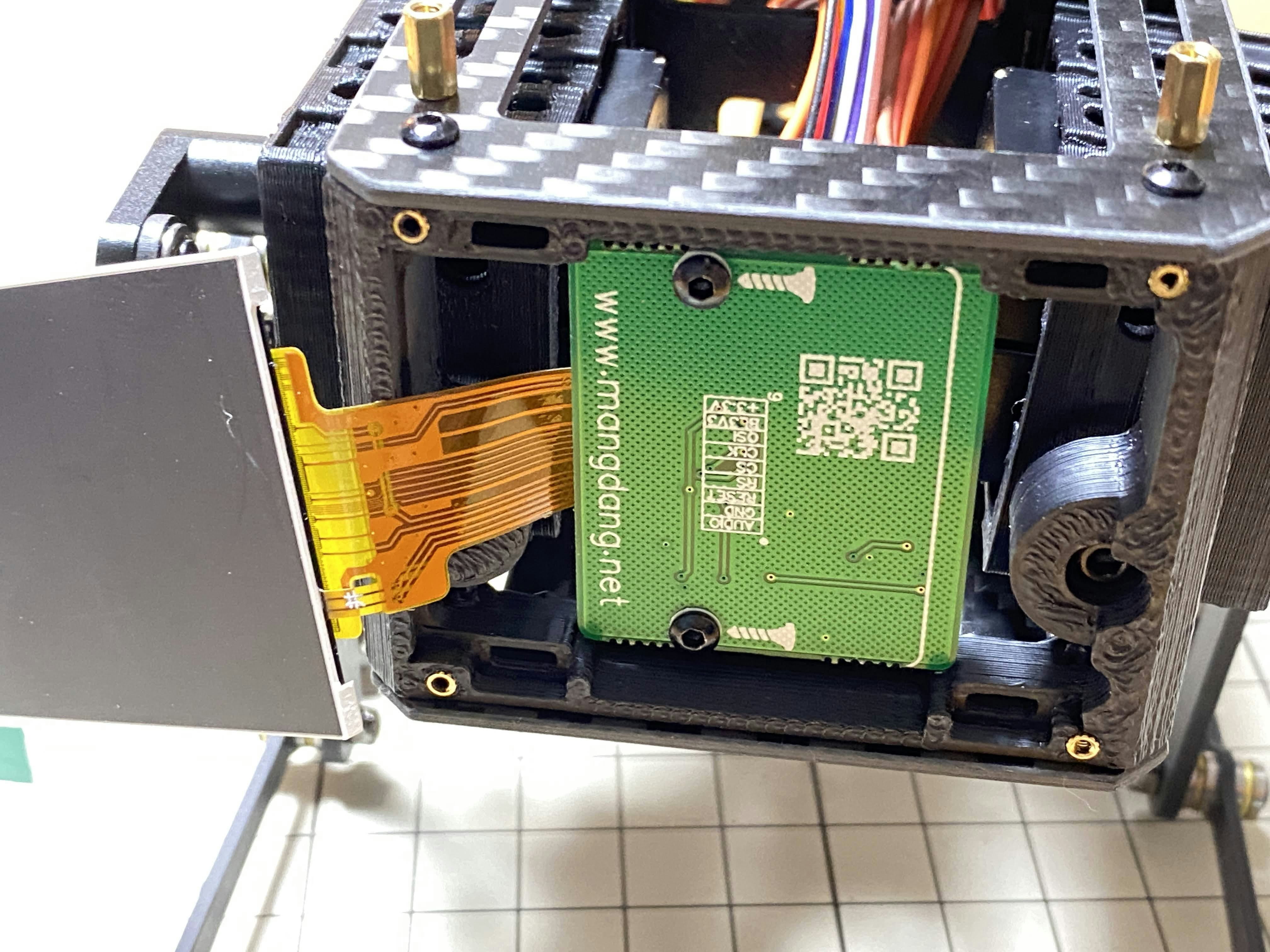
M2x5mmのボルト2本を使用します。ディスプレイの保護シールはここで取りましょう。ディスプレイと専用基板の間に通る薄いフレキシブルケーブル(通称フレキ)をディスプレイの端で折ります。基板、ディスプレイの順に本体に取り付けます。ディスプレイを取り付ける際に、フレキがなるべく奥にいくように棒状の物で軽く押すと良いです。
Use two M2x5mm screws. Remove the protective sheet for the display. Fold the thin flexible cable at the edge of the display. Attach the board and the display to the main unit. When attaching the display, you can use a stick to gently push the flexible cable, so that it goes as far back as possible.
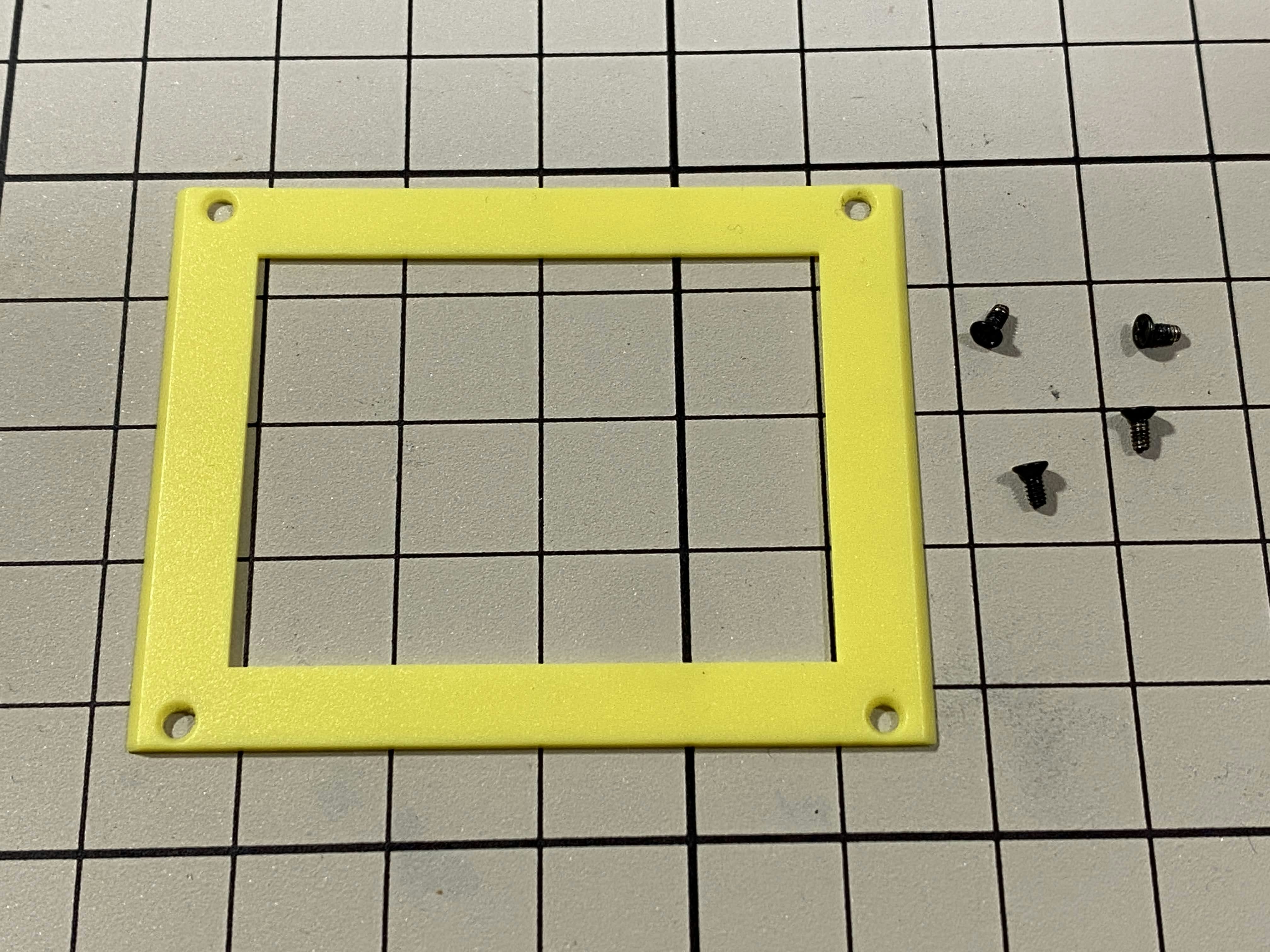
顔の枠 / Frame of face
M1.4x3mmの皿ネジを4本使用します。黄色いパーツには表裏の区別があるので気をつけましょう。
Use four M1.4x3mm countersunk screws. Be careful with the yellow parts as it has a front and back.
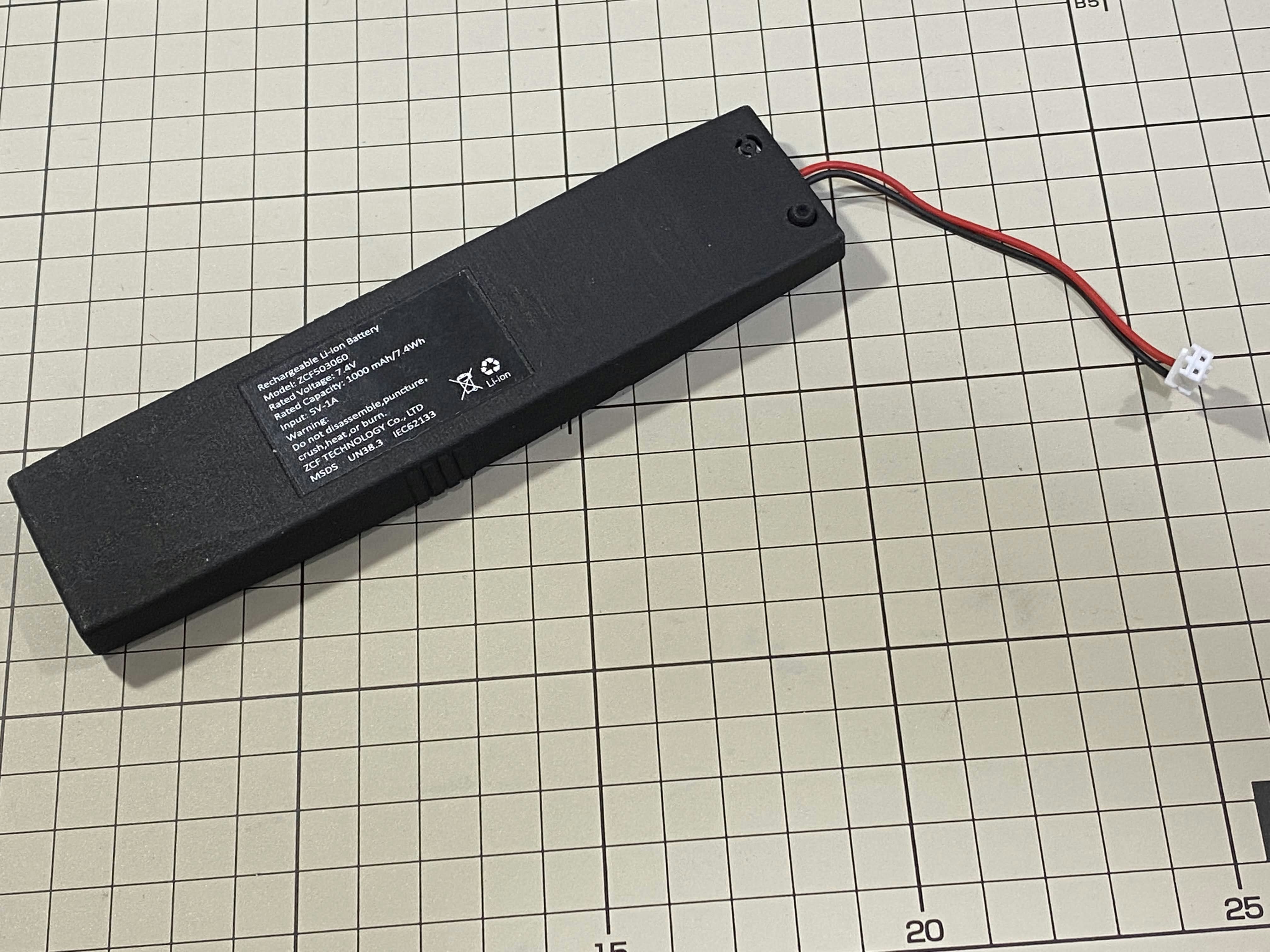
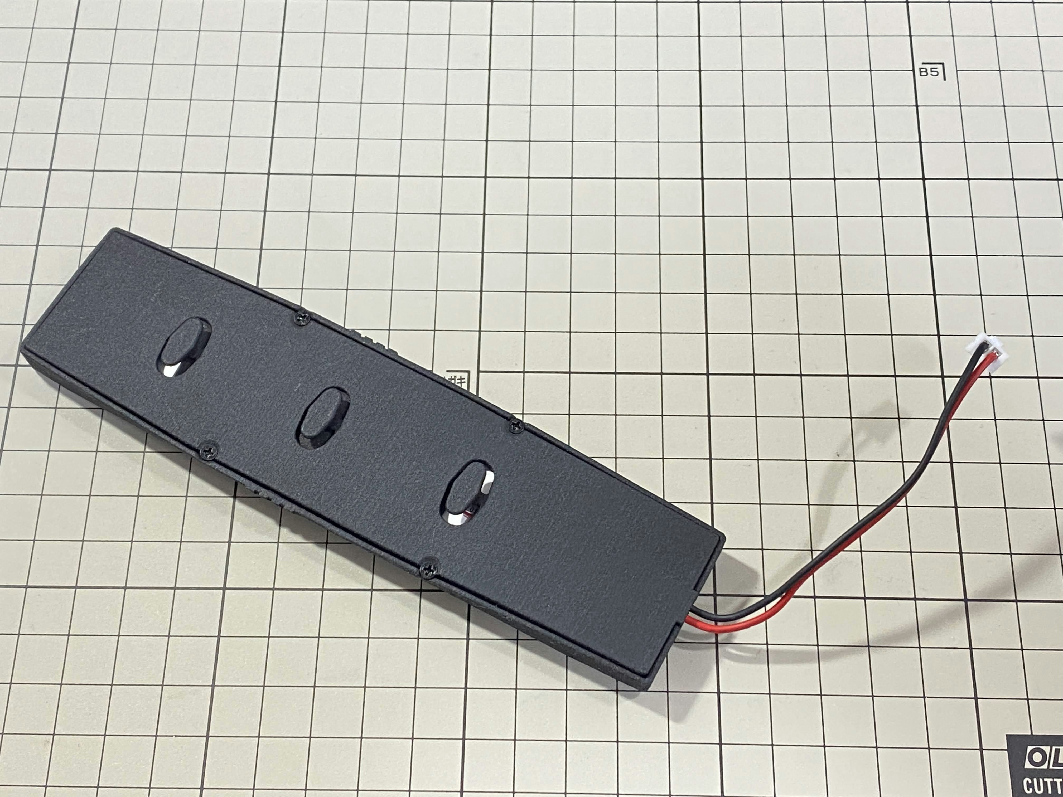
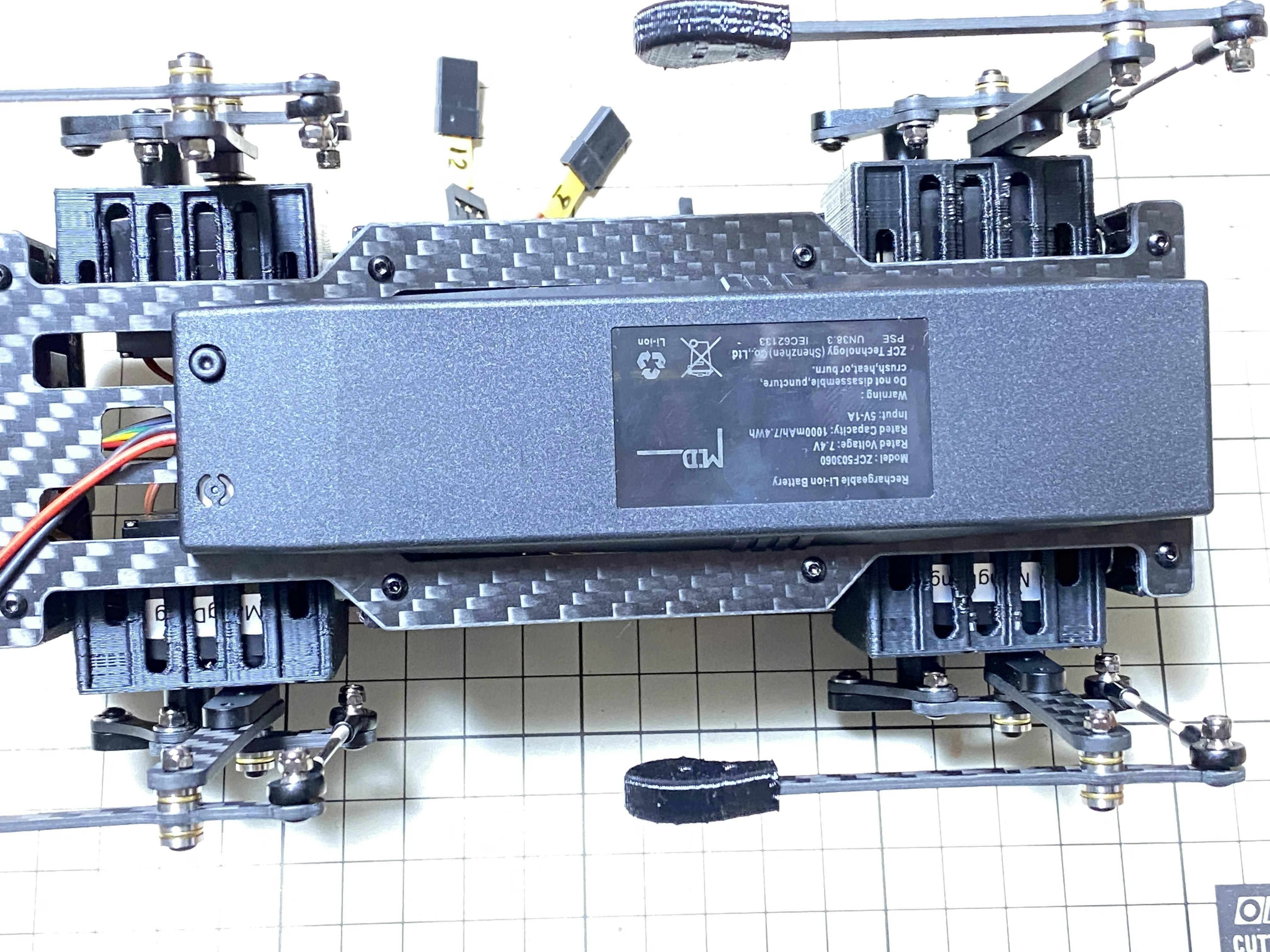
バッテリー / battery
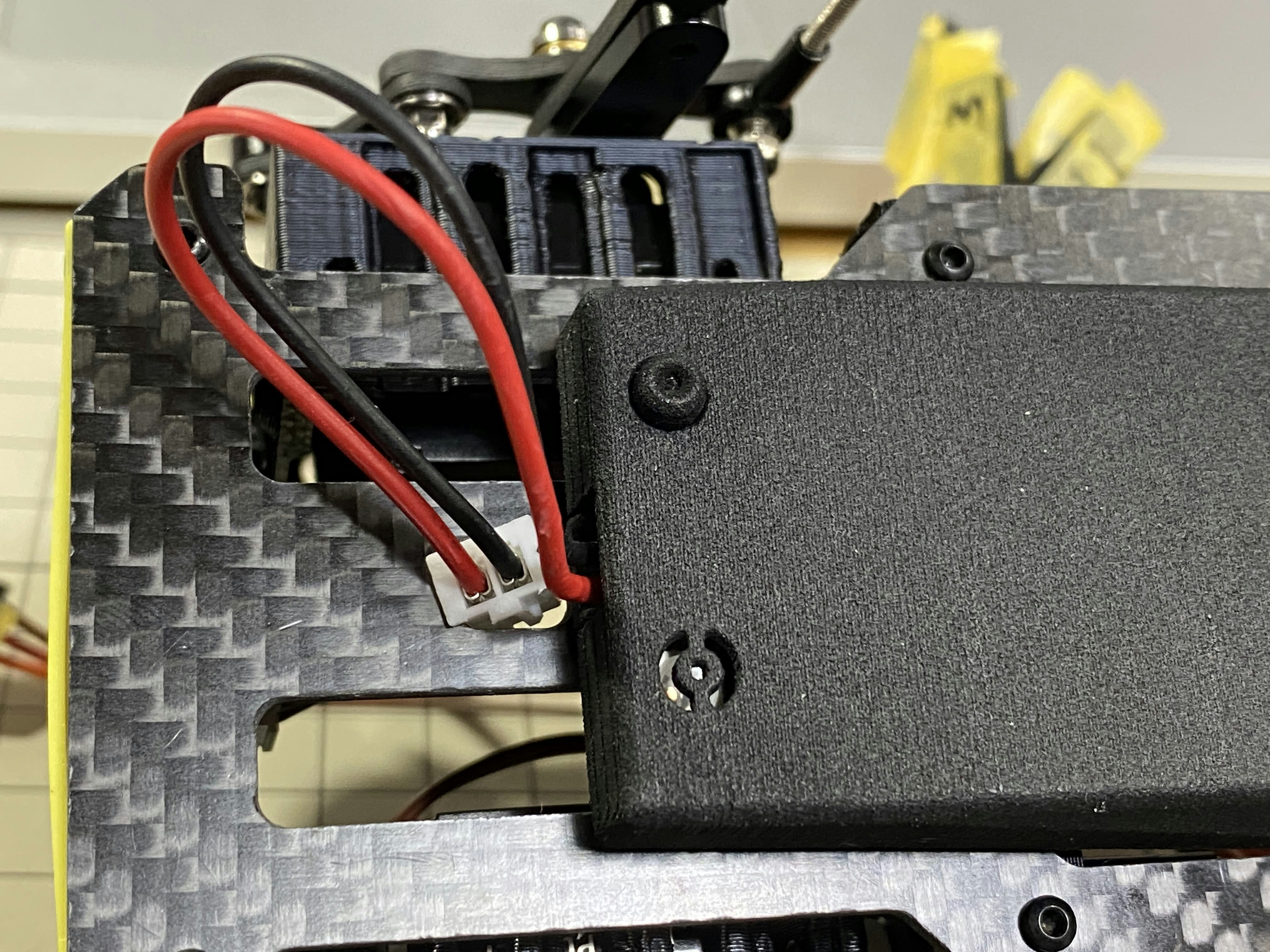
バッテリーパックを取り付けます。前後の向きに気をつけましょう。底からバッテリーを上にはめて、後ろにぐっとずらし固定します。ケーブルを底のプレートの穴に通し、上まで持ってきます。
Install the battery pack. Be careful of the front and rear orientation. Fit the battery from the bottom to the top, then slide it backwards and secure it. Pass the cable through the hole in the bottom plate and bring it up to the top.
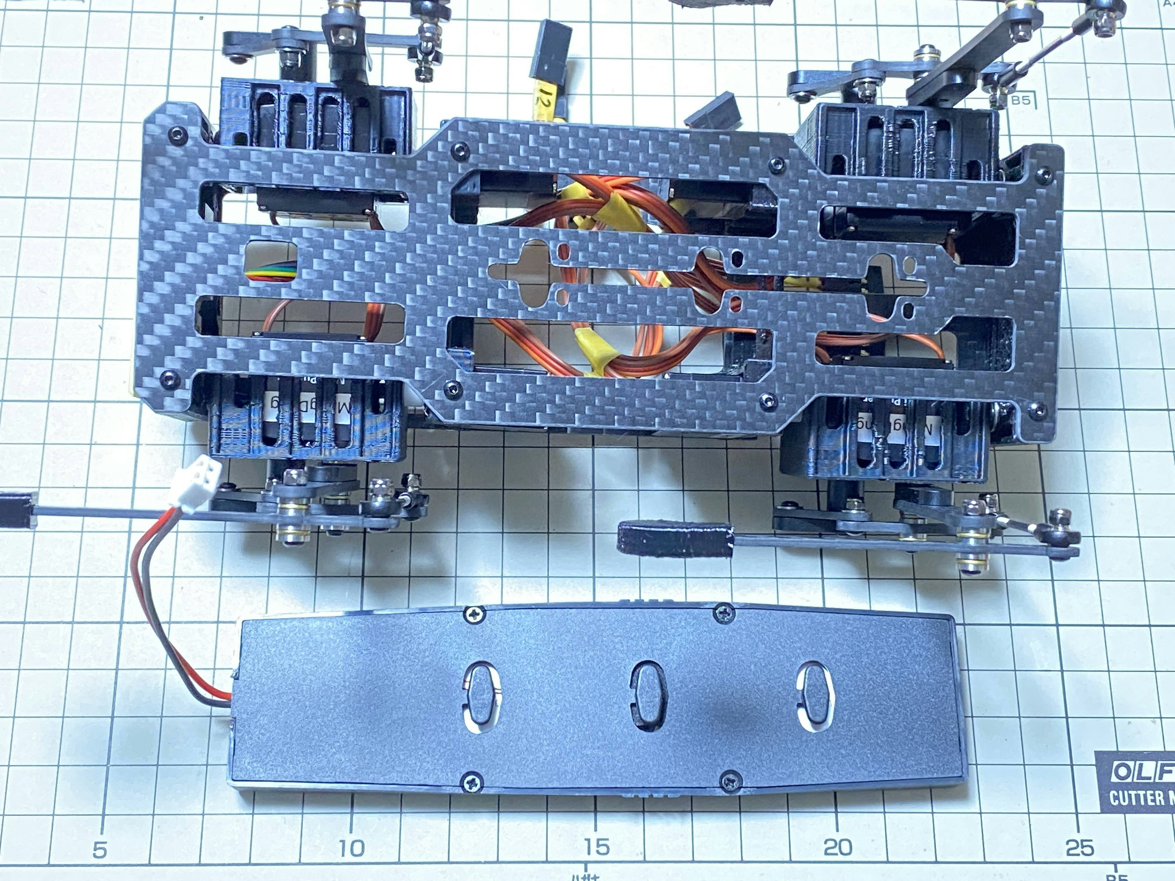
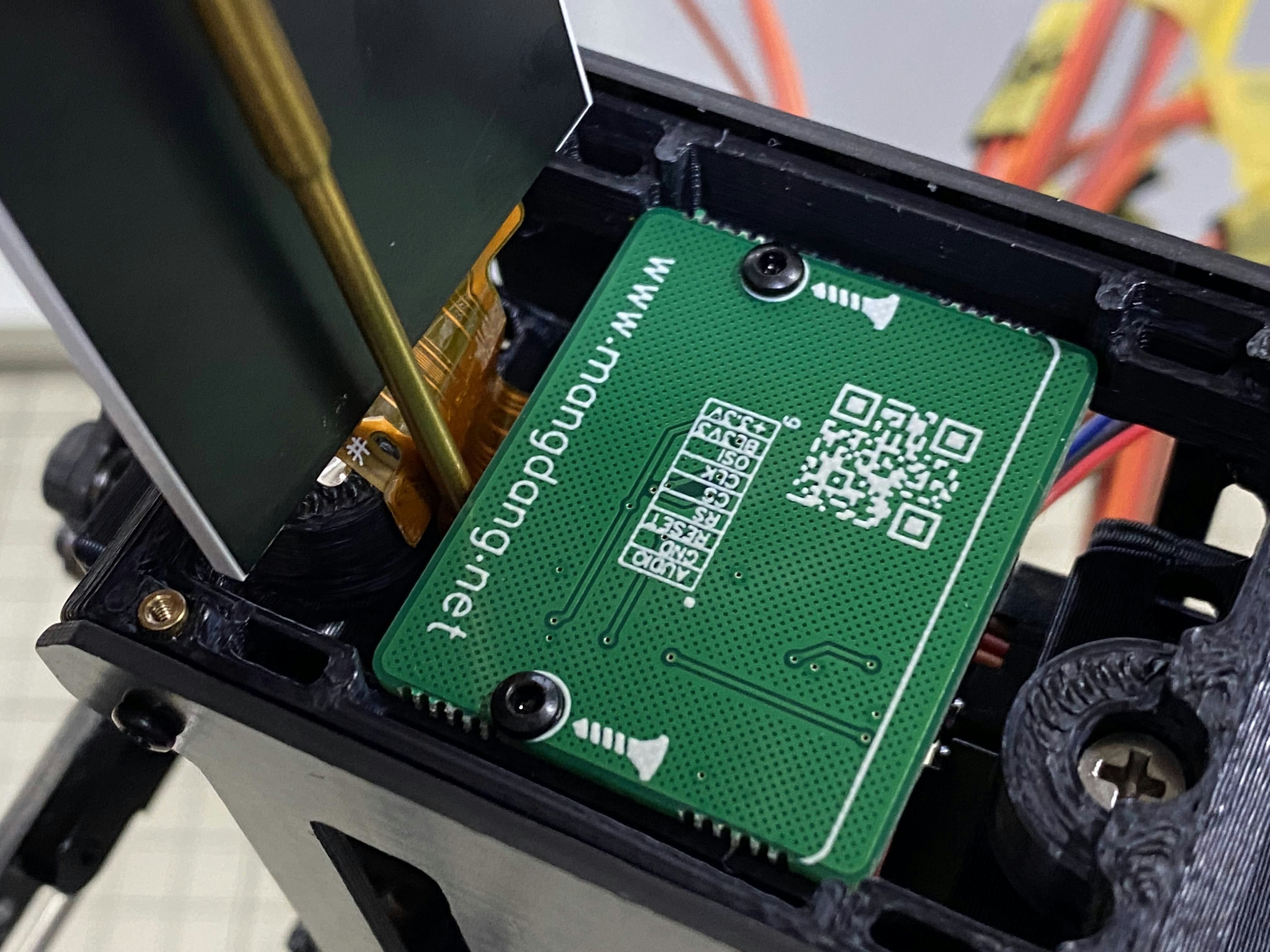
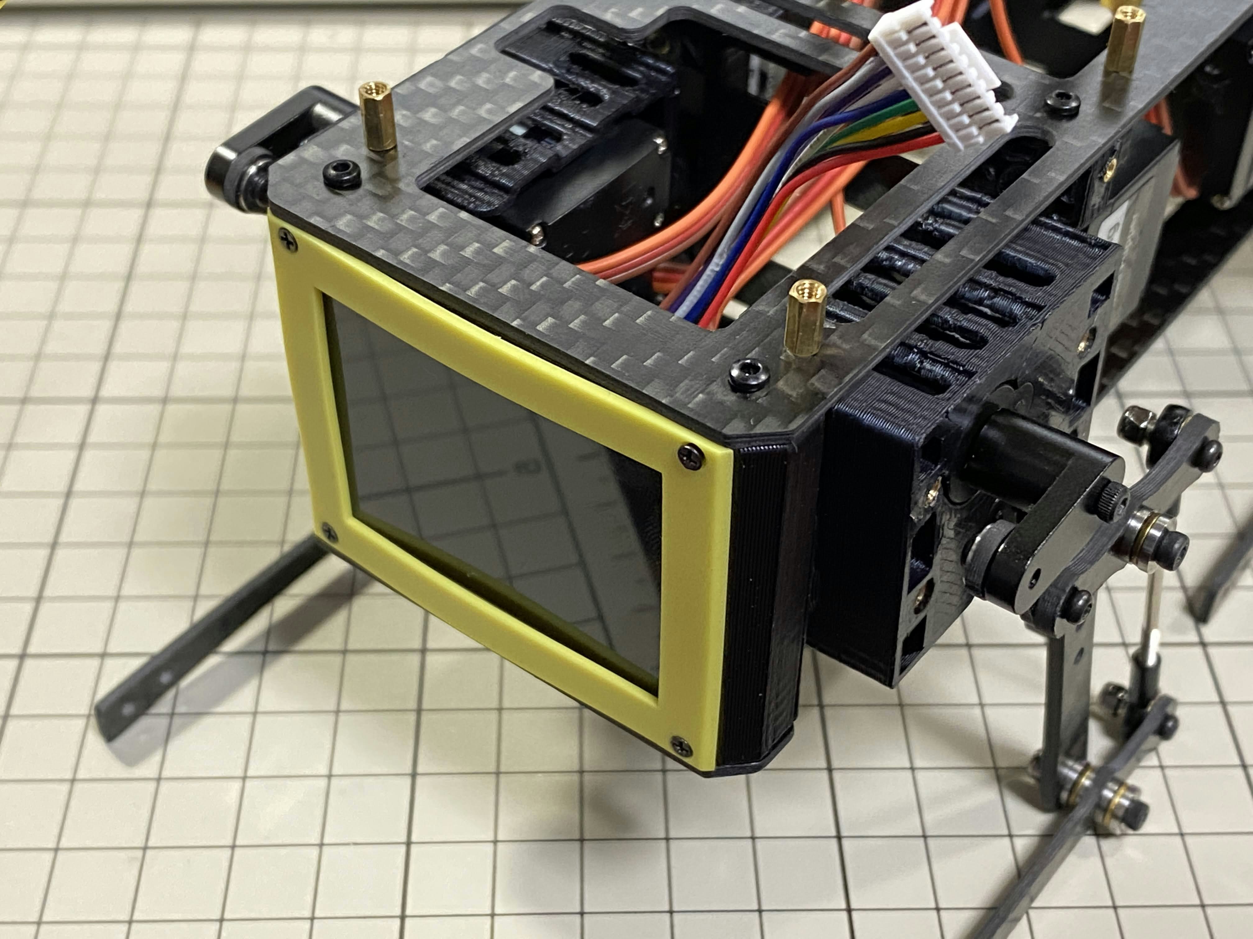
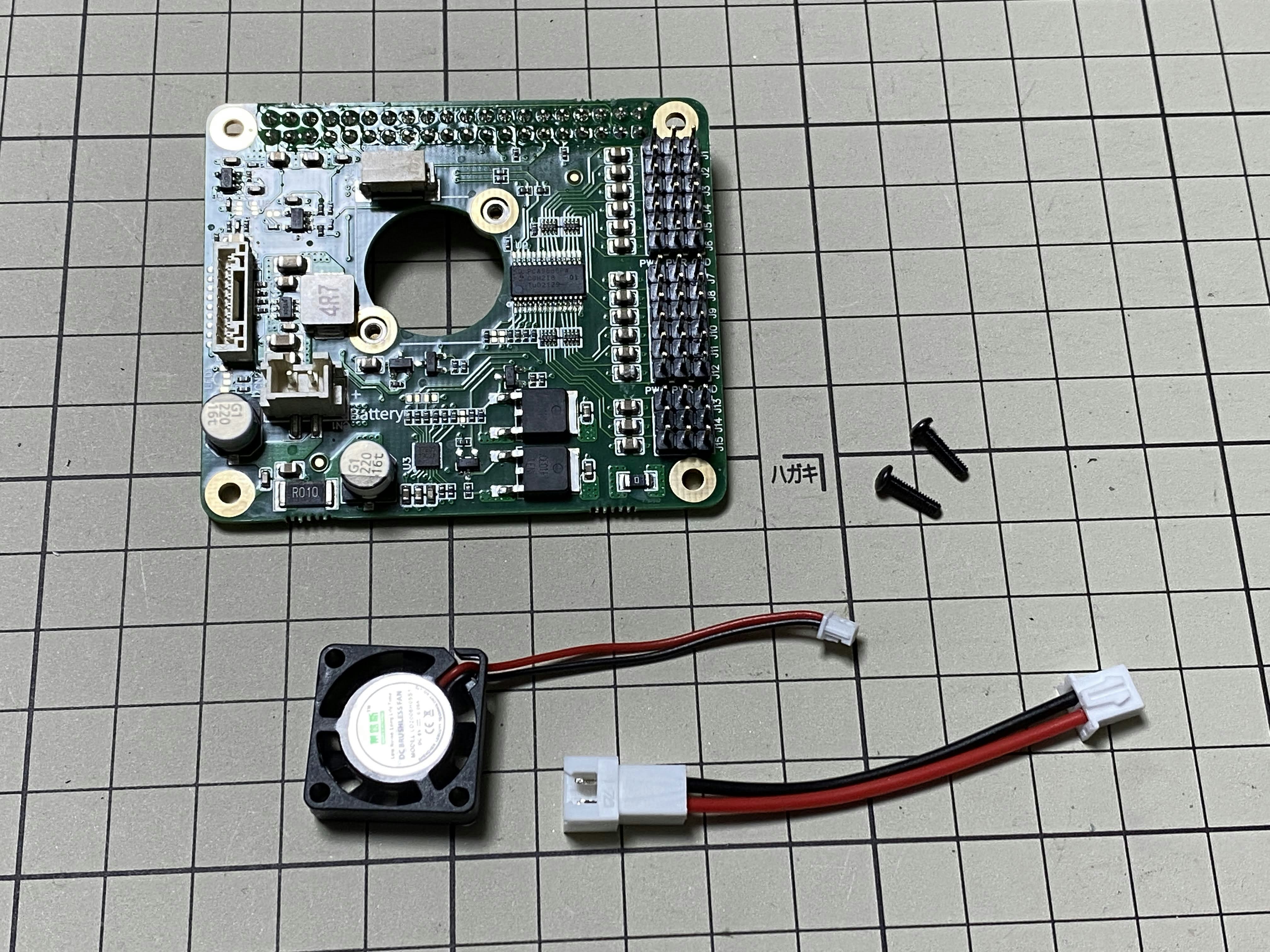
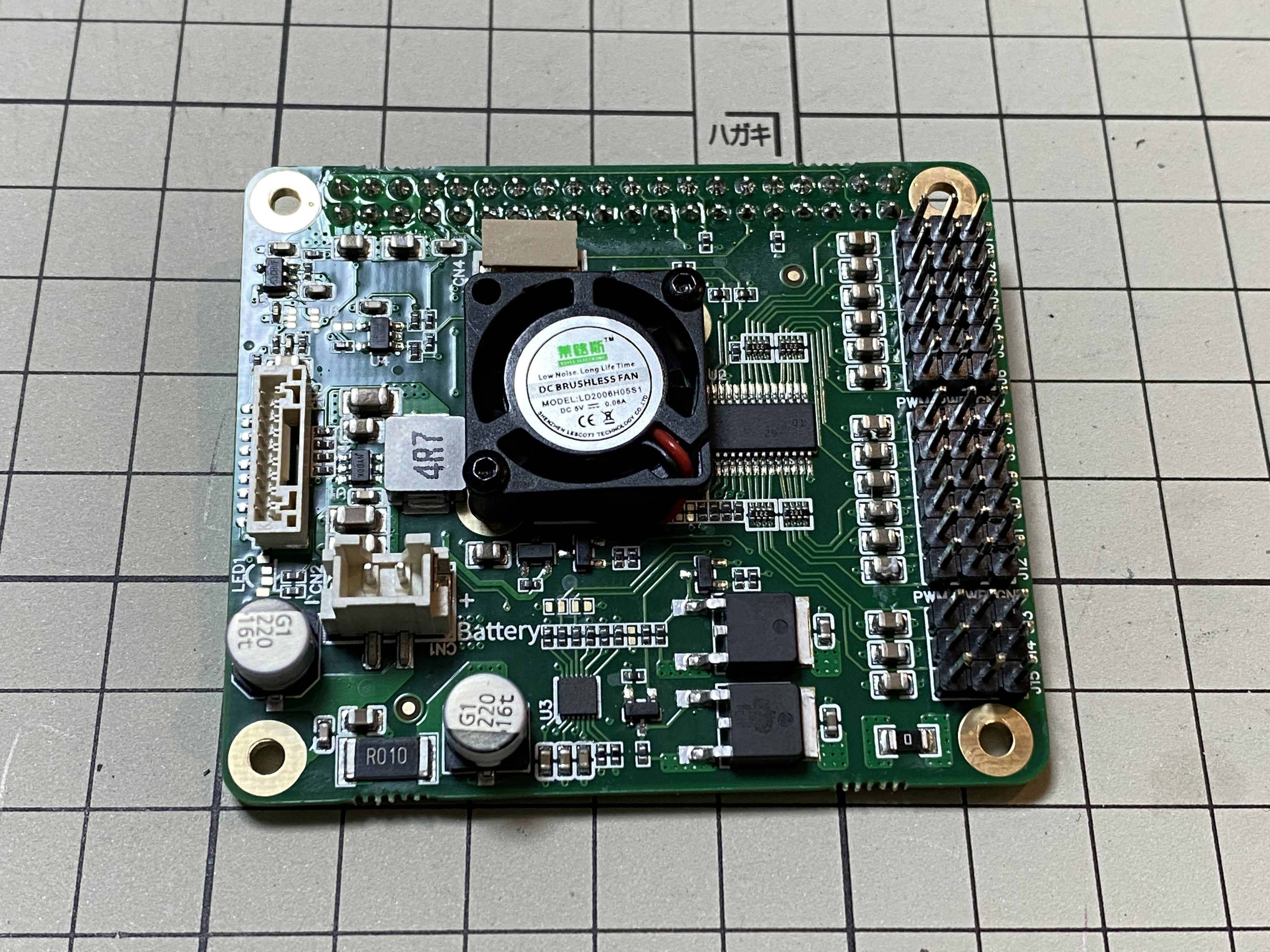
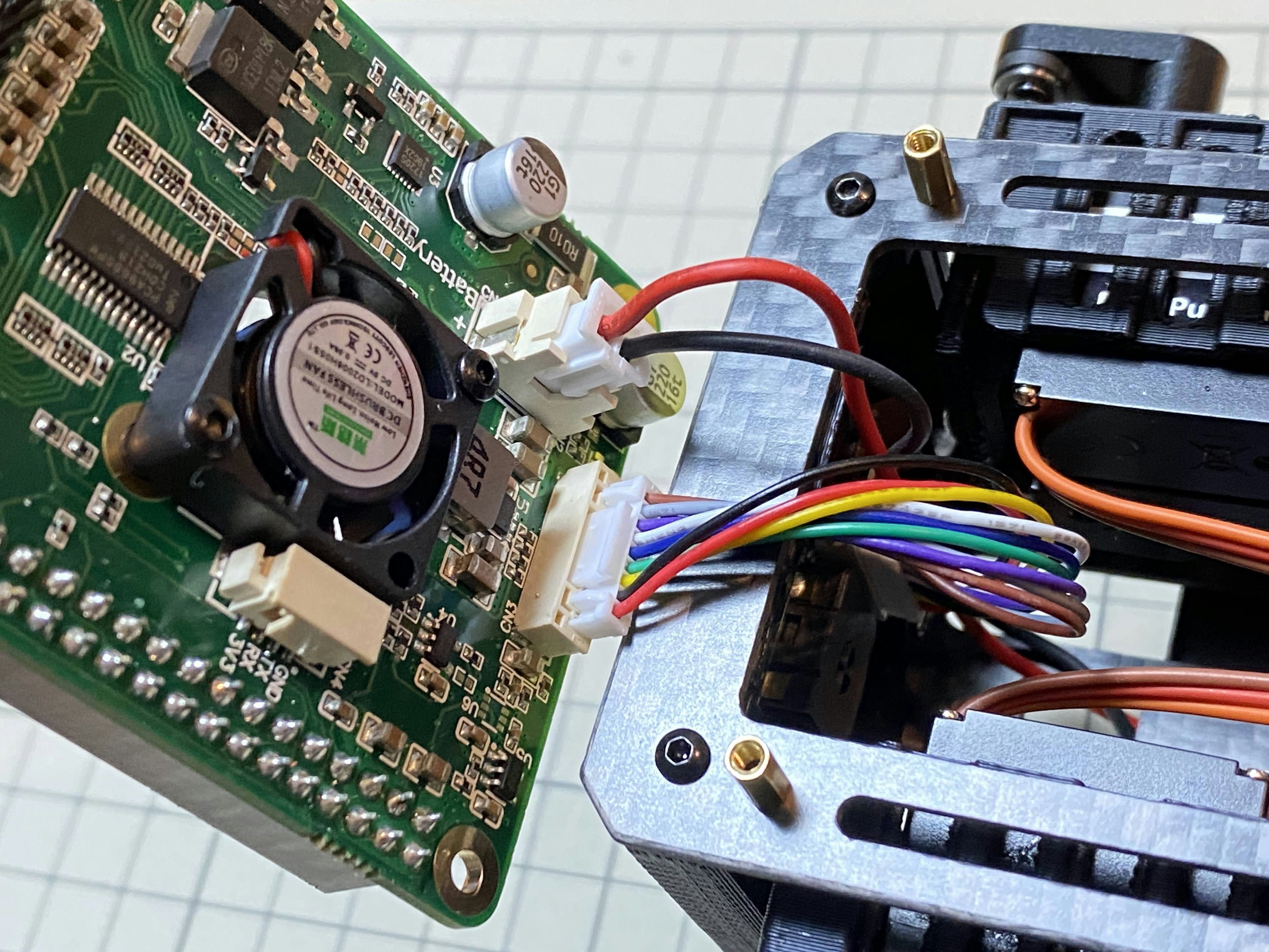
カスタム回路基板 / custom circuit board
基板にファンをM2x8cmのボルト2本で固定します。ファンのケーブルを基板上のコネクタに挿します。
Fix the fan to the custom board with two M2x8cm bolts. Plug the fan cable into the connector on the board.
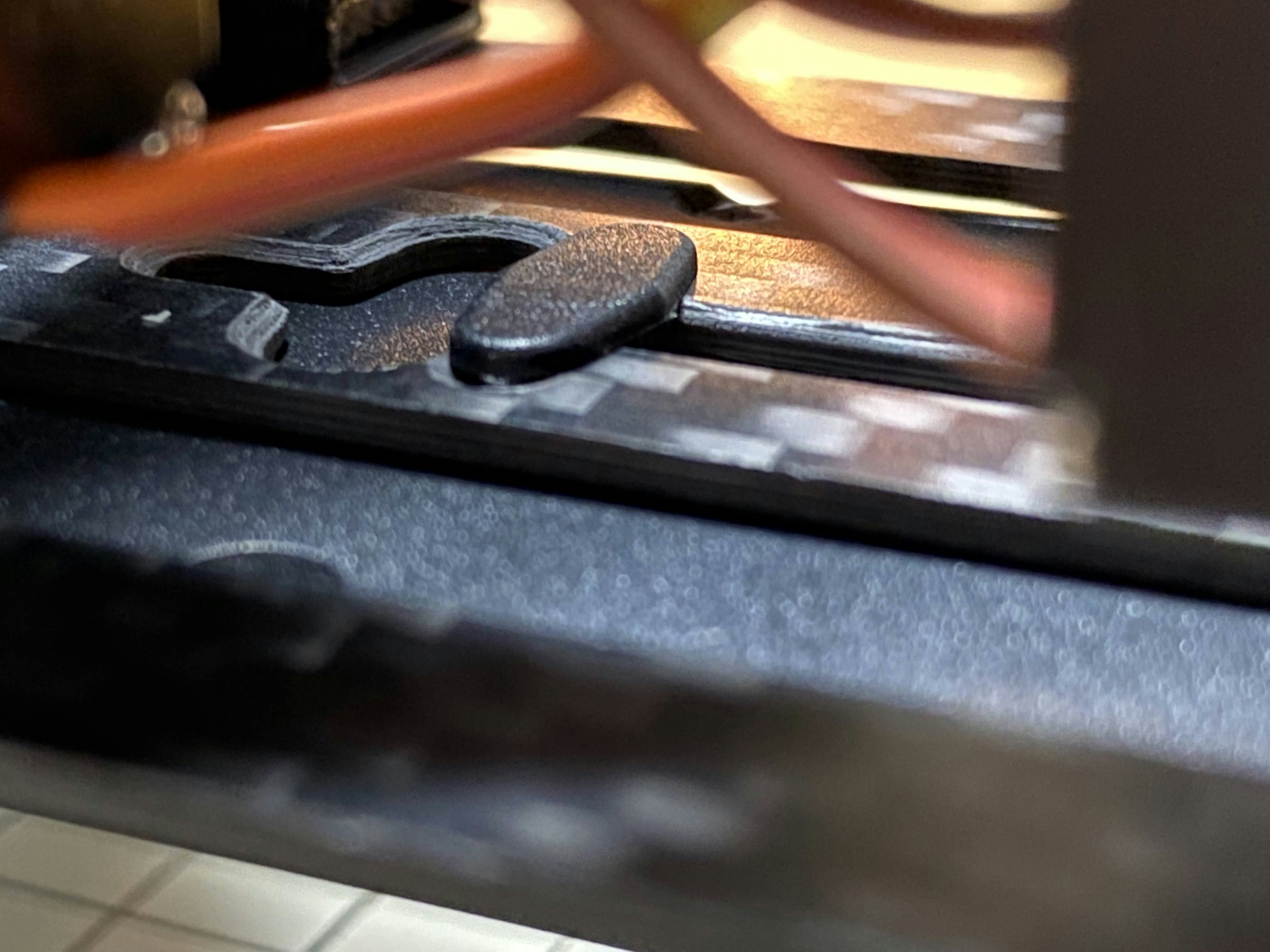
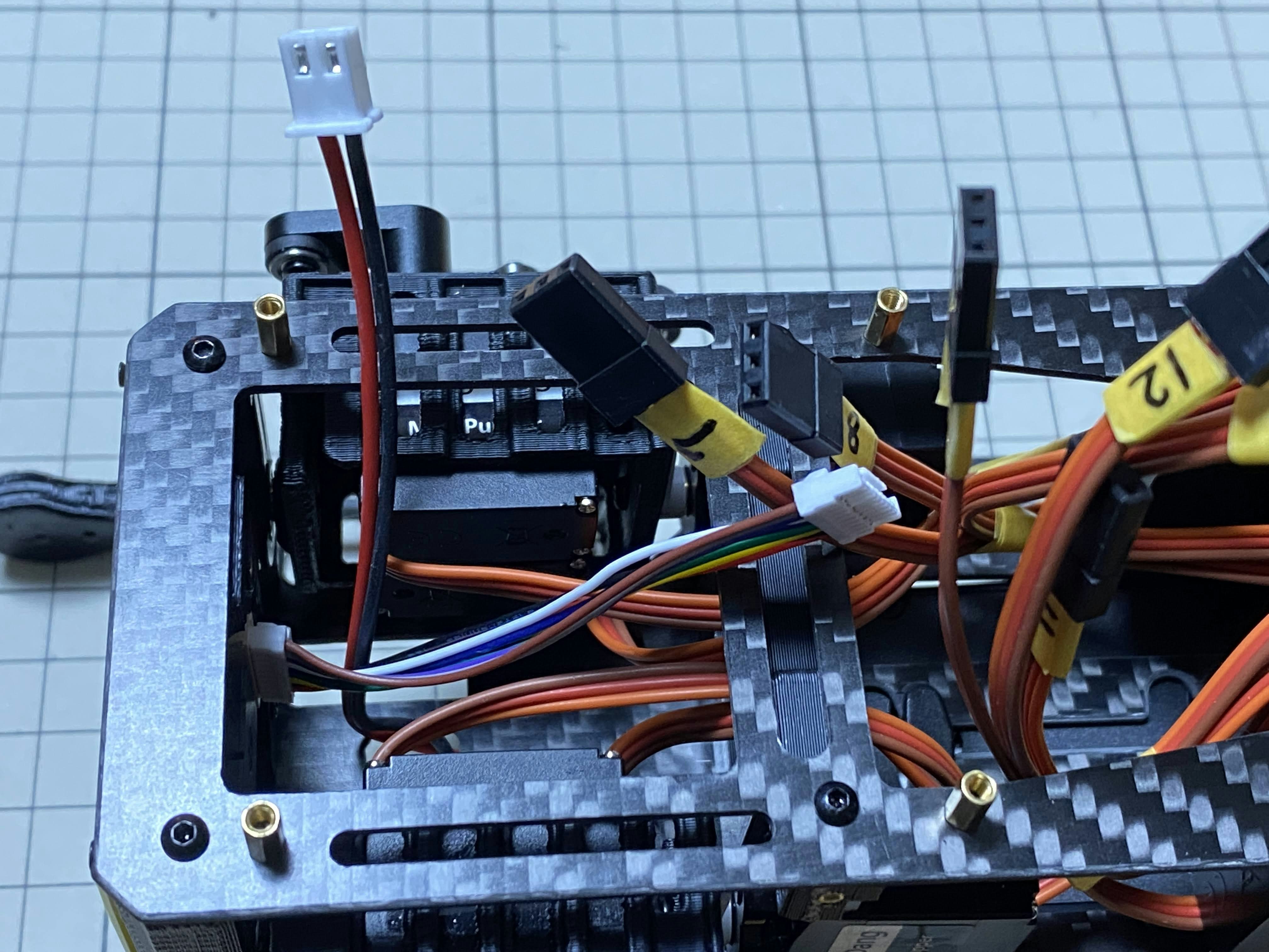
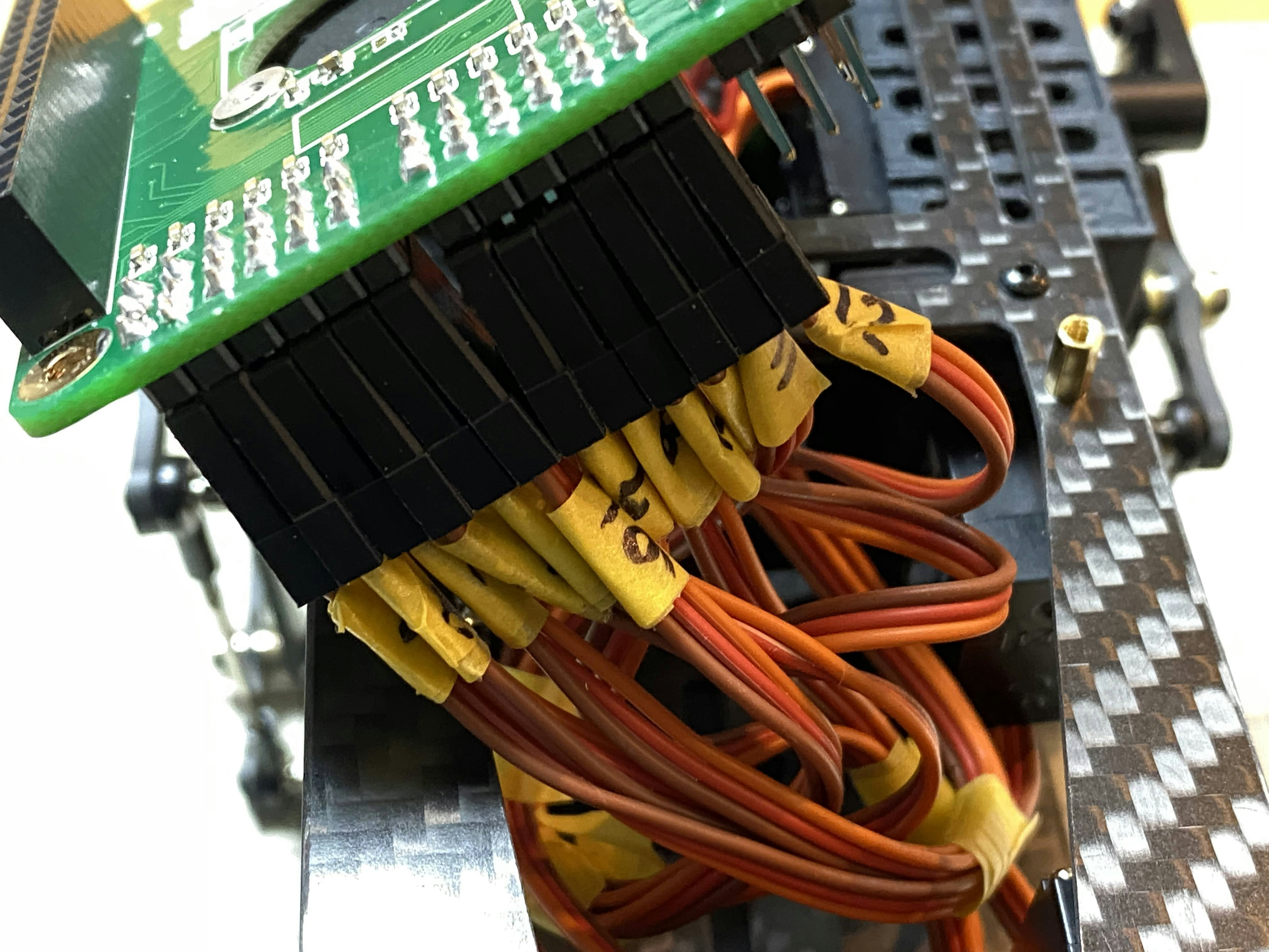
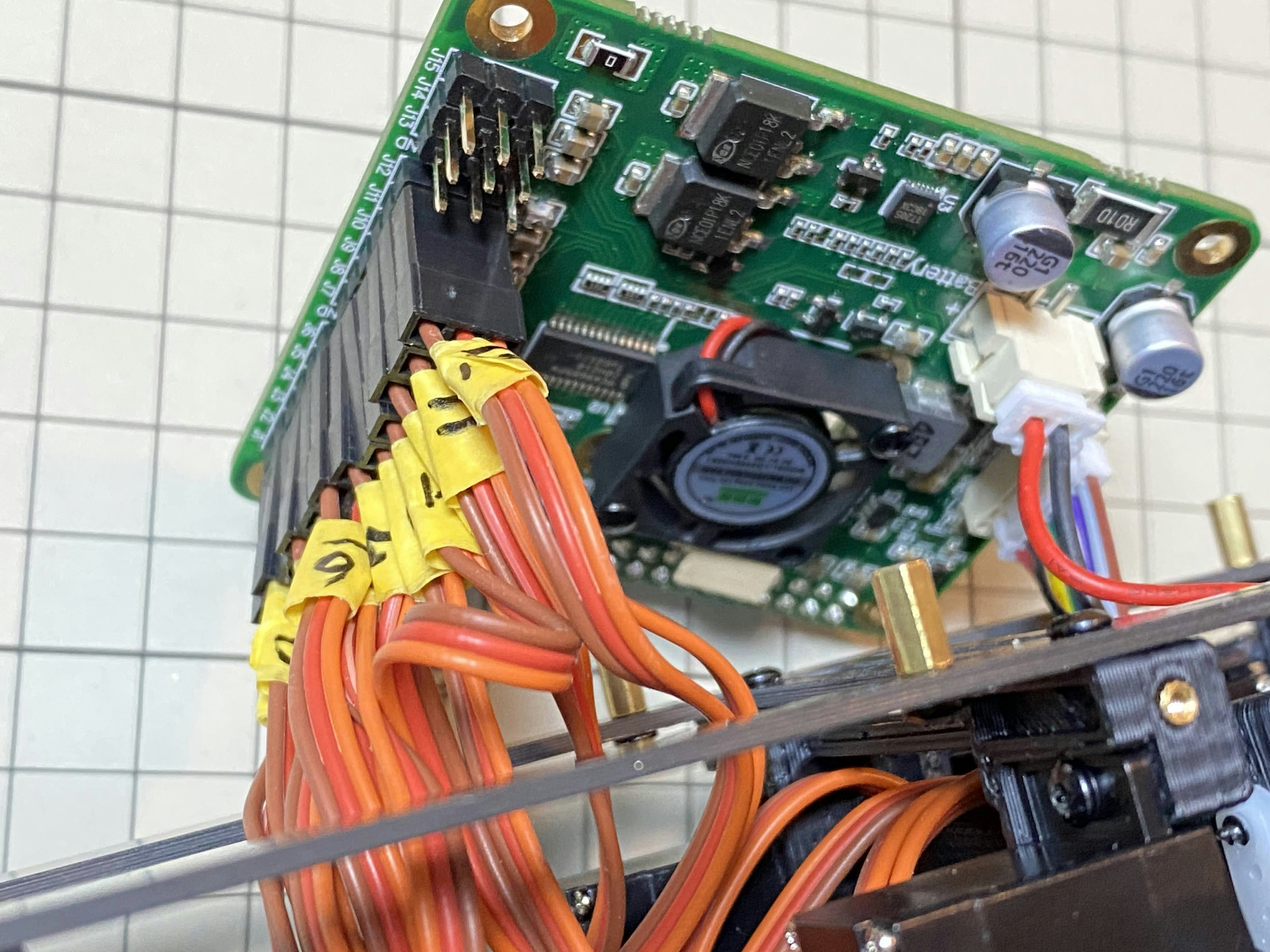
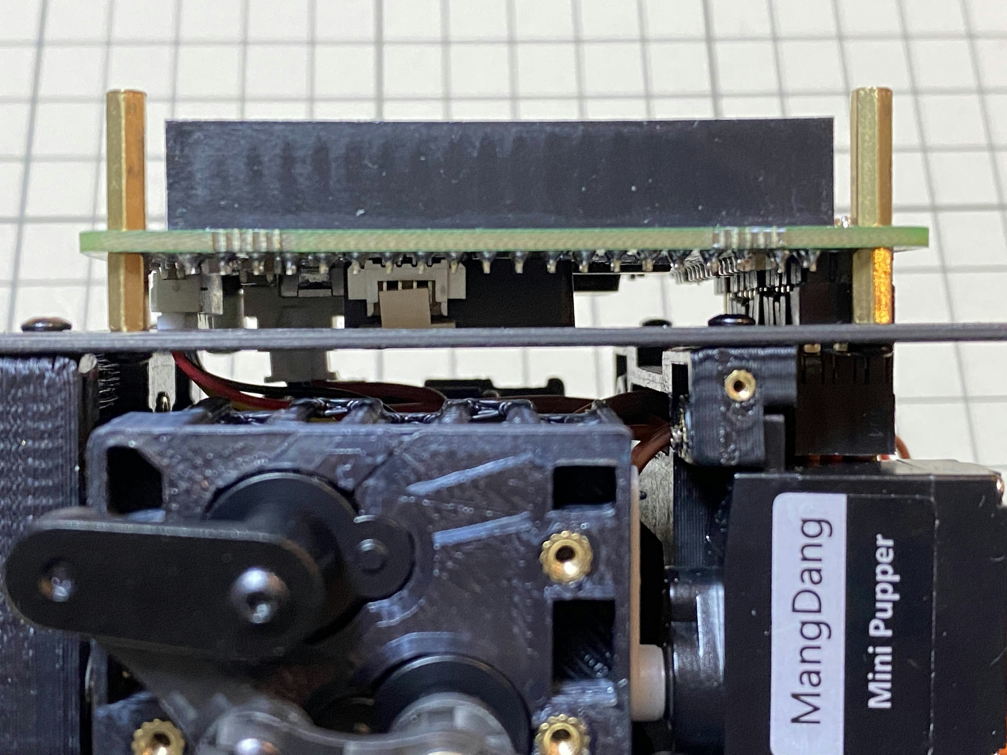
次に、長い支柱4本を使用します。最初にディスプレイのケーブルをカスタム回路基板に挿します。次にバッテリーのケーブルを挿します。次にサーボのケーブルを12本挿します。写真で説明すると、左から1,2,3...12と挿していきます。茶色がGNDなので全て手前になるように挿しましょう。12本のケーブルを挿したらカスタム回路基板をぐっと力を入れてボティに近づけます。ケーブルの反発で基板が浮いてきますが、長い支柱を4本挿して固定しましょう。
Next, use four long supports. First, plug the display cable into the custom circuit board. Then, plug in the battery cable. Next, you need to insert the 12 servo cables. In the picture from left to right: 1,2,3.... . 12. After inserting the 12 cables, pull the custom circuit board closer to the body. The board may float, but you can use four long posts to hold it in place.
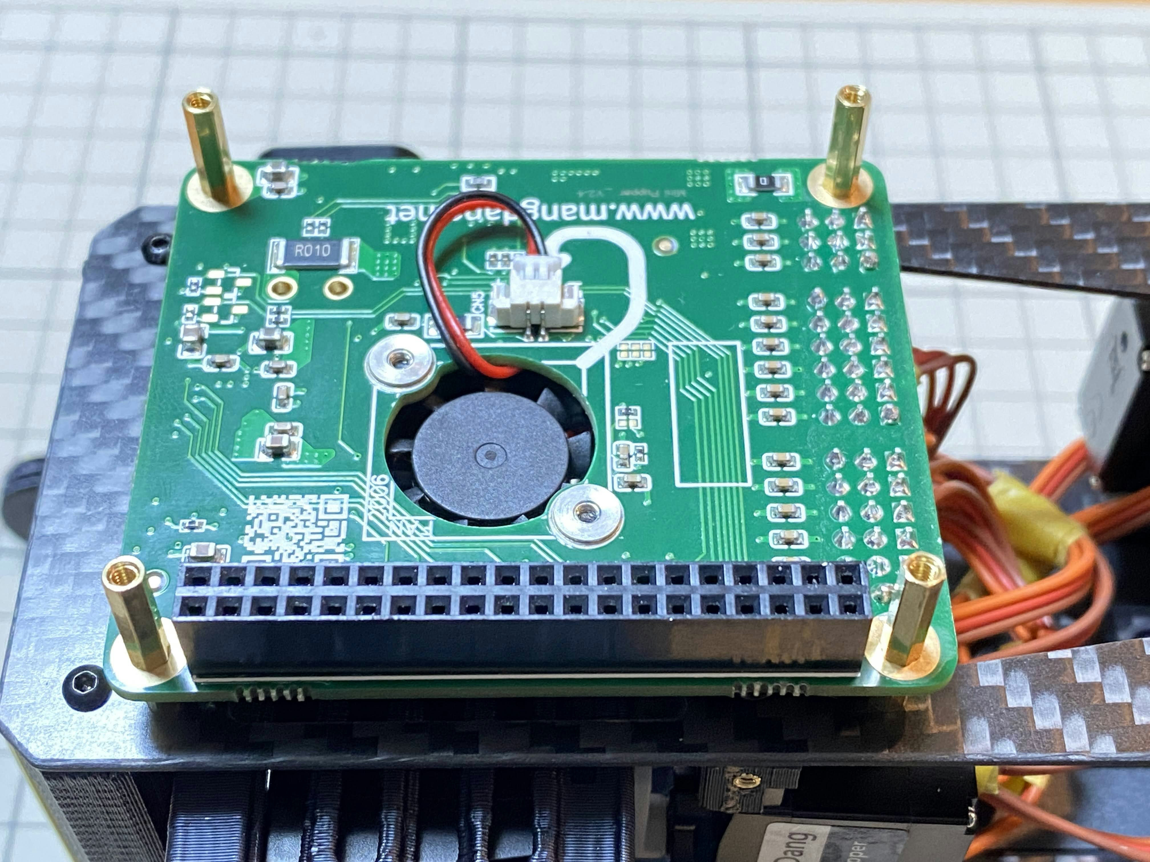
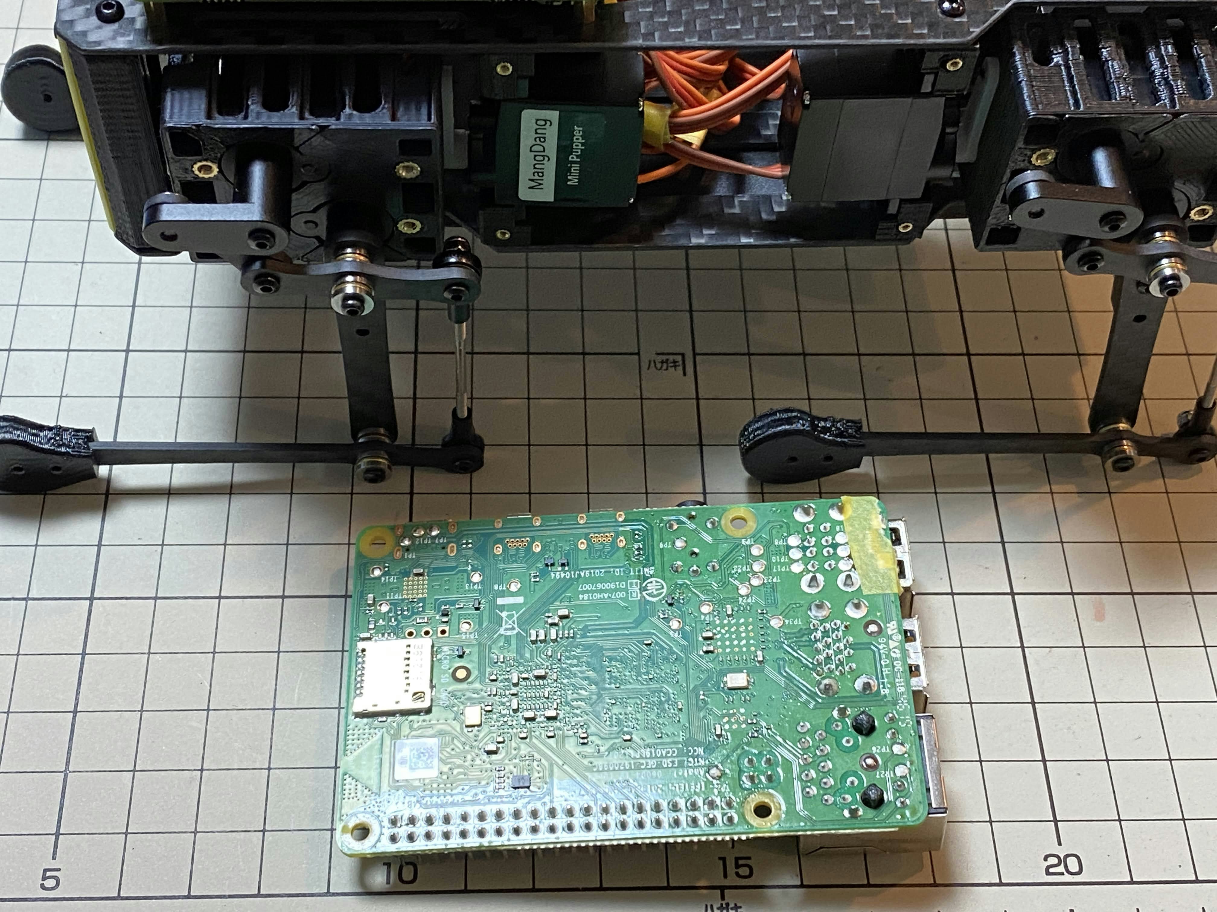
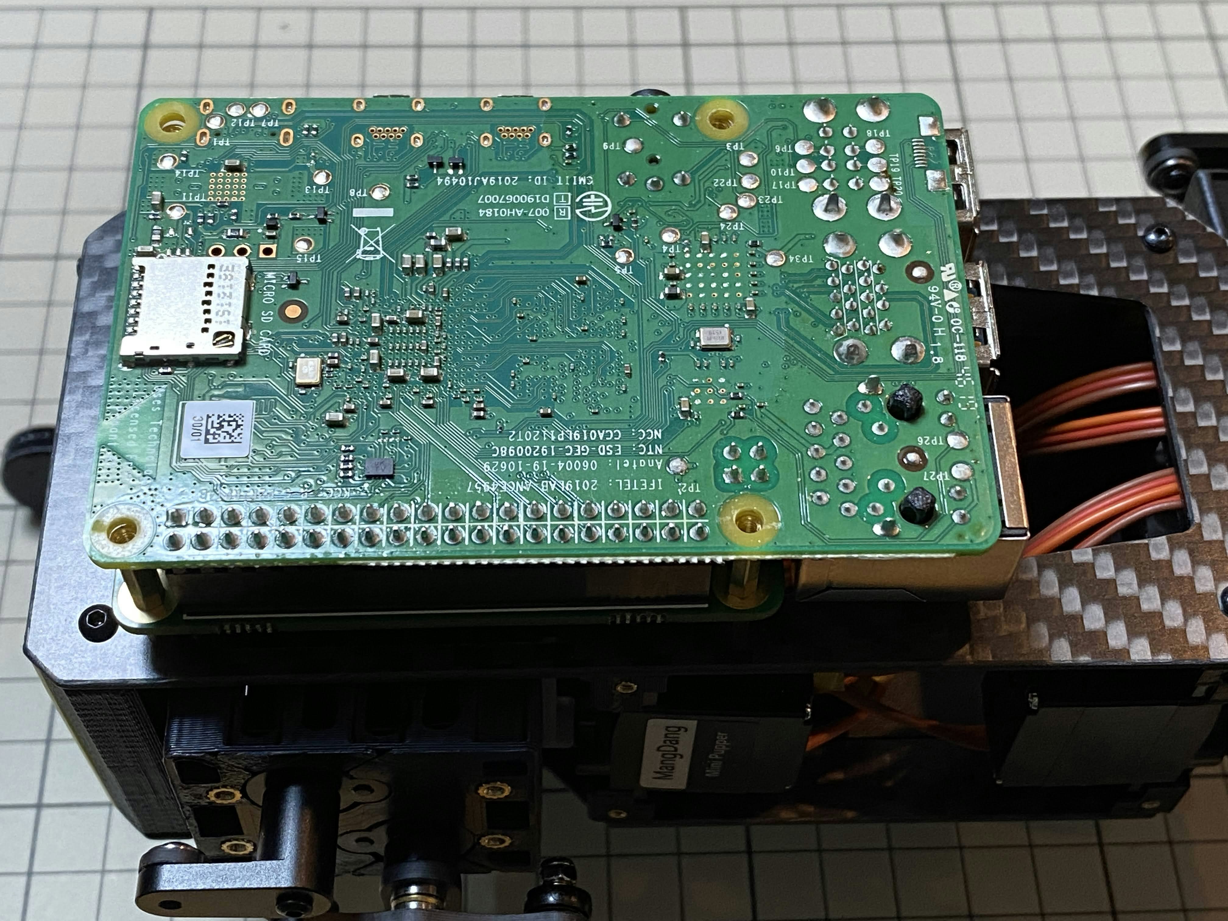
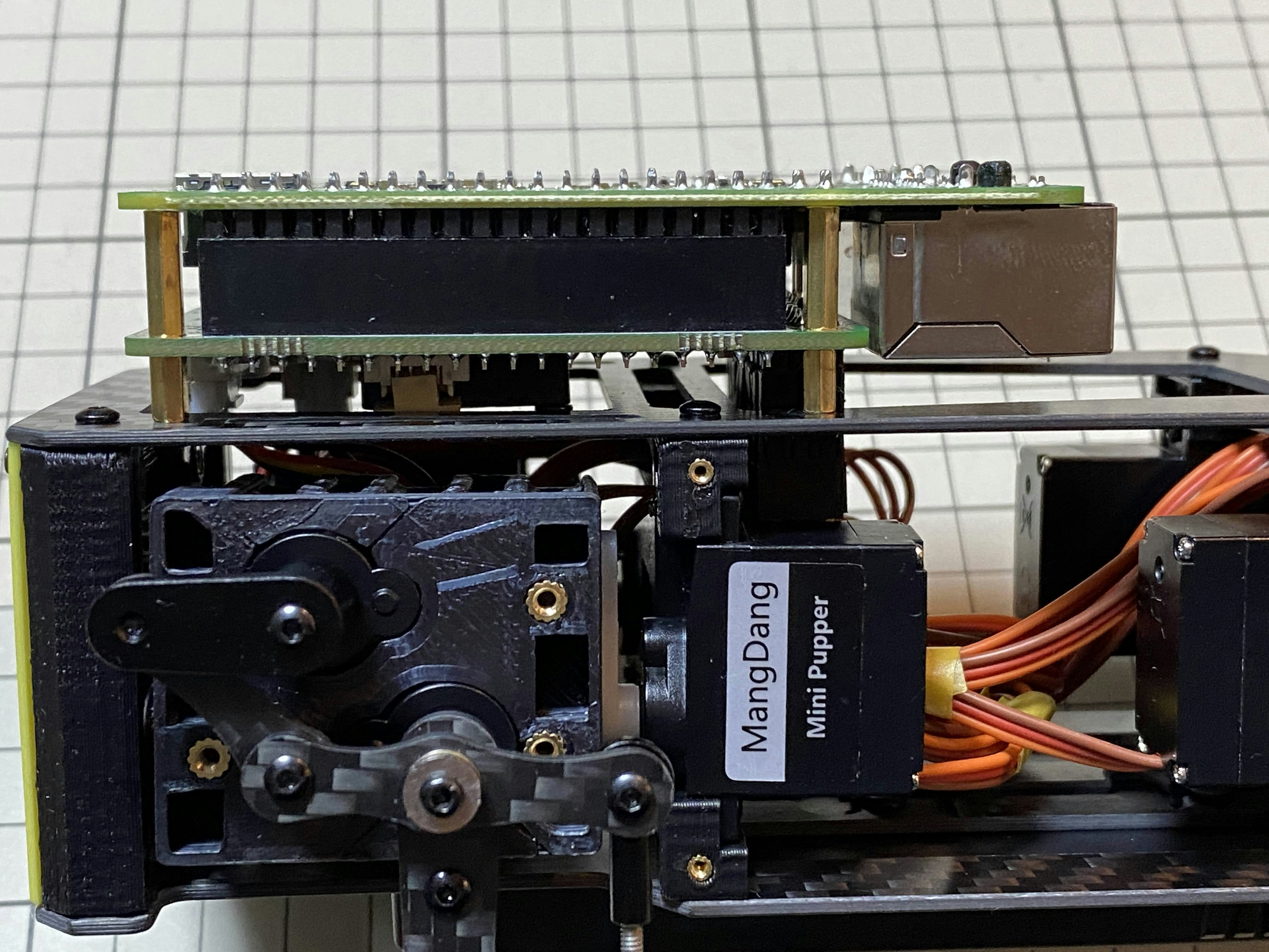
Raspberry Pi 4
次工程 / next step
最後は外装の取り付けです。ただ、動作しない場合、バラしてやり直す可能性がありますので、一旦動作確認をやります。動作確認が完了したら、見た目を仕上げましょう。
The last step in the assembly process is the mounting of the exterior. However, if your Mini Pupper doesn't work, you may have to take it apart and re-assemble it. So, once the operation check is complete, it is time to finish the appearance.
次は【Mini Pupper 5】 ソフトウェアセットアップです。
Next step is on 【Mini Pupper 5】 Software Setup.
分からないことがあったらここにコメントを書くか、 #minipupper #ミニぷぱ を付けてツイートすれば、優しい人が教えてくれますよ。
If you have any questions, write a comment here or tweet it with #minipupper #minipupa and tech friends will be happy to help.
参考 / Reference
- でべさん の 「Mini Pupper」がやってきた!(1: make 編)
- でべさんの 組み立てツイート