Introduction
If we want to connect PowerVS to the internet, the first thing that comes to mind is using the default external IP address. However, PowerVS has a service-wide firewall configured by default, which does not allow inbound traffic on non-default ports or source IP address restriction. Therefore, I don’t think this approach is commonly used in production environments.
https://cloud.ibm.com/docs/power-iaas?topic=power-iaas-network-security
In production environments, I believe the most common approach for implementing communication control that meets specific requirements is to set up a VSI functioning as a proxy or NAT gateway on the VPC side to communicate with the internet. While this approach adequately meets functional requirements, users have been required to set up and maintain the VSI themselves.
In this article, I’ll introduce a method that minimizes the need for custom user configuration by using VPC’s Network Load Balancer (NLB) service instead of VSI. A key advantage is that you don’t need to specify proxies or NAT gateways at the OS layer of each individual LPAR; instead, you can configure everything transparently at the network layer. While both outbound and inbound traffic can be configured, this article focuses on a setup that enables outbound communication from PowerVS to the Internet.
I have described the configuration for inbound traffic here, but since the outbound settings are a prerequisite for inbound traffic, please implement the configuration described in this article first.
Overview
This architecture is described in the Docs below.
https://cloud.ibm.com/docs/power-iaas?topic=power-iaas-powervs-public-network-setup#inbound-overview
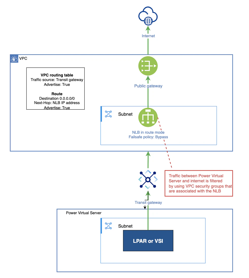
The key points of the configuration are as follows:
・Enable the public gateway in the VPC subnet
・Create an NLB in the VPC using routing mode (the key point is to set the Failsafe policy to Bypass)
・In the VPC’s ingress routing table, create a rule that routes traffic destined for 0.0.0.0/0 from the Transit Gateway to the NLB (and advertise this rule to the Transit Gateway)
・Since 0.0.0.0/0 is defined in the ingress table, all packets entering this VPC from the Transit Gateway will be affected by this route definition. I think it would be clearer to create a dedicated VPC for this purpose.
Actual Configuration
Prerequisites
Assume the following have already been created:
・VPC(As I mentioned in the overview, since we’re defining a route for 0.0.0.0/0, I think it’s safer to create a new VPC specifically for this purpose to avoid affecting other routes.)
・VPC subnet
・PowerVS workspace
・PowerVS subnet
・LPAR
・Transit Gateway (connected to the VPC and PowerVS workspace)
Create an NLB in routing mode
Create a load balancer for the VPC.
https://cloud.ibm.com/infrastructure/provision/loadBalancer
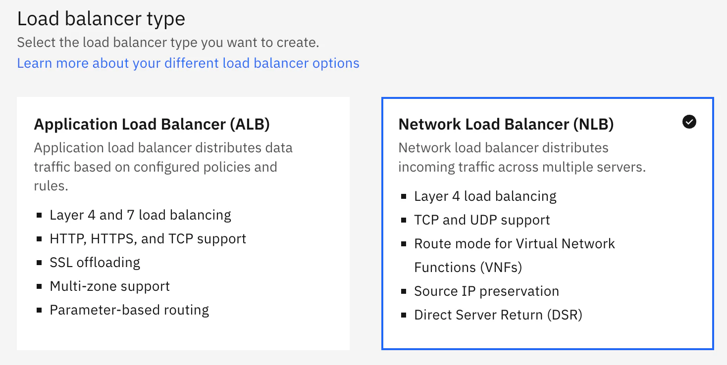
Select NLB.
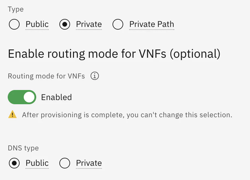
Select the “Private” type and enable “Enable routing mode.” The DNS type does not affect this configuration, so either option is fine. If you are comfortable with the domain appdomain.cloud being used in the FQDN of the NLB that will be created, “Public” is a good choice (we won't be using the FQDN in this case anyway). If you want to create an FQDN using a domain you specify, order a DNS Service and select the ‘Private’ type. For this example, I will proceed with “Public”.
Leave the Back-end pools and Front-end listeners fields empty.
Proceed with the default security groups. If you already have specific security groups you want to use, you may select them.
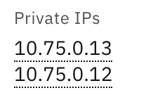
The NLB (routing mode) will be assigned two IP addresses. In the subsequent steps, you will define this IP address as the next hop in the routing table; when doing so, please use the first IP address displayed (10.75.0.13 in the example below). Although the NLB (routing mode) is assigned an FQDN, you can specify the IP address directly when defining it in the routing table.
NLB configuration
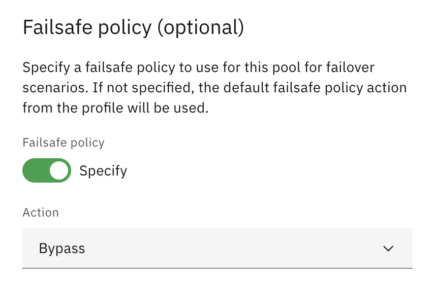
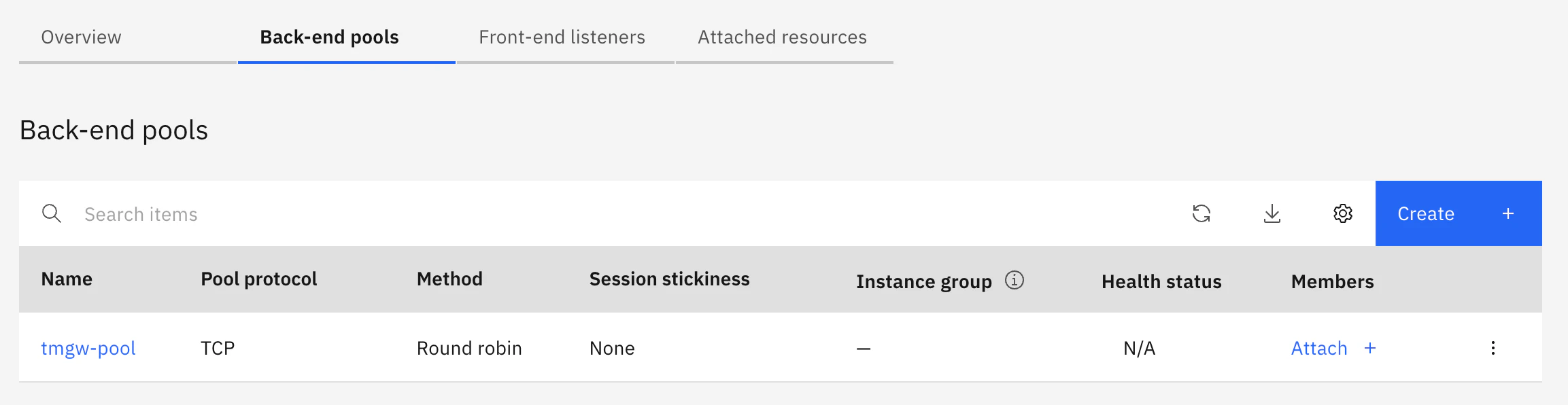
Create a backend pool. The key is to enable the failsafe policy and specify “Bypass.” You can leave the members empty.
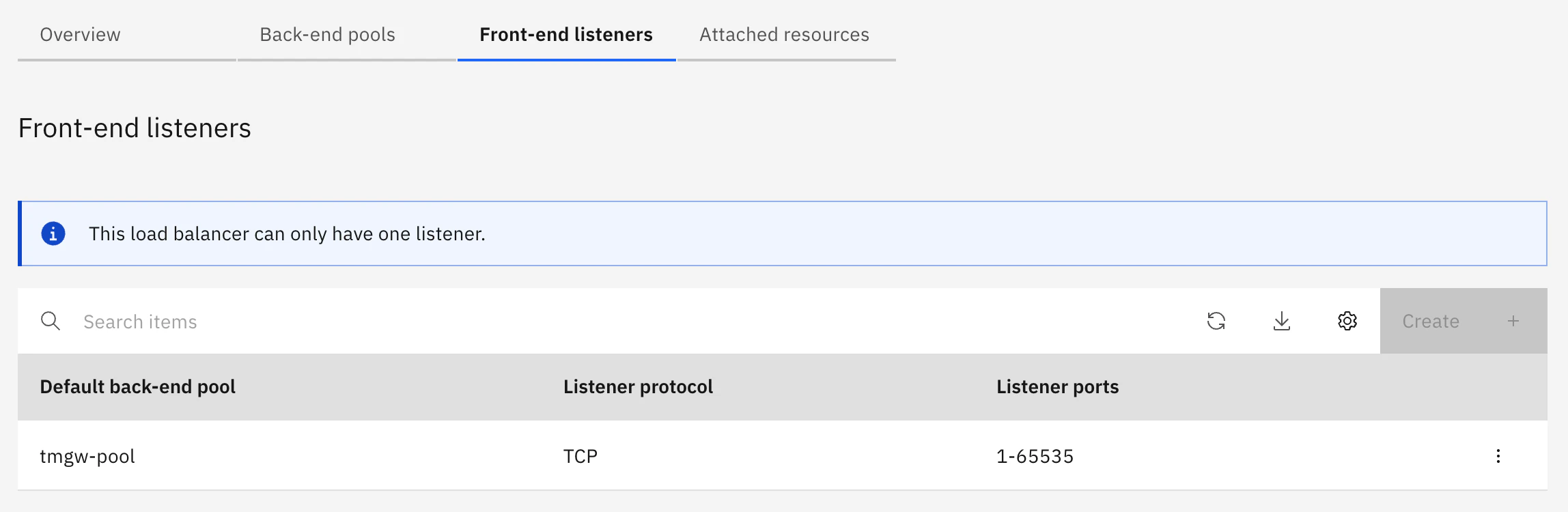
Create a front-end listener associated with the backend pool you created.
Configure Security Groups for the NLB
Add a rule to the security groups configured for the NLB to allow traffic from PowerVS.
Also, allow outbound traffic from the NLB.
Create a routing table
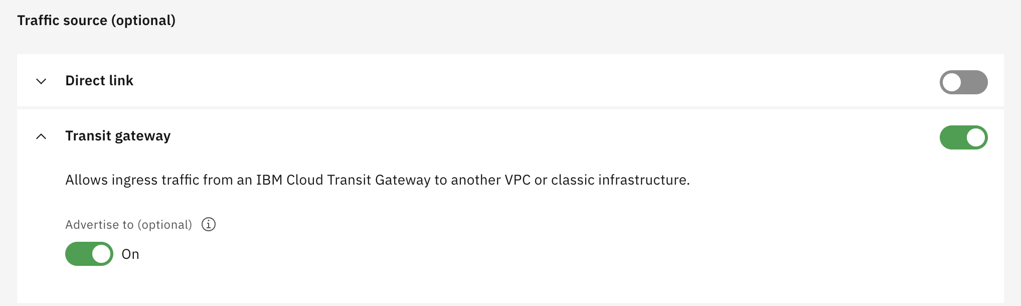
Create a routing table to forward packets entering the VPC via the Transit Gateway from the PowerVS workspace to the NLB. Under “Traffic source”, select the Transit Gateway and enable “Advertise.”
Add routing information to the table to deliver packets destined for 0.0.0.0/0 to the NLB's IP address.
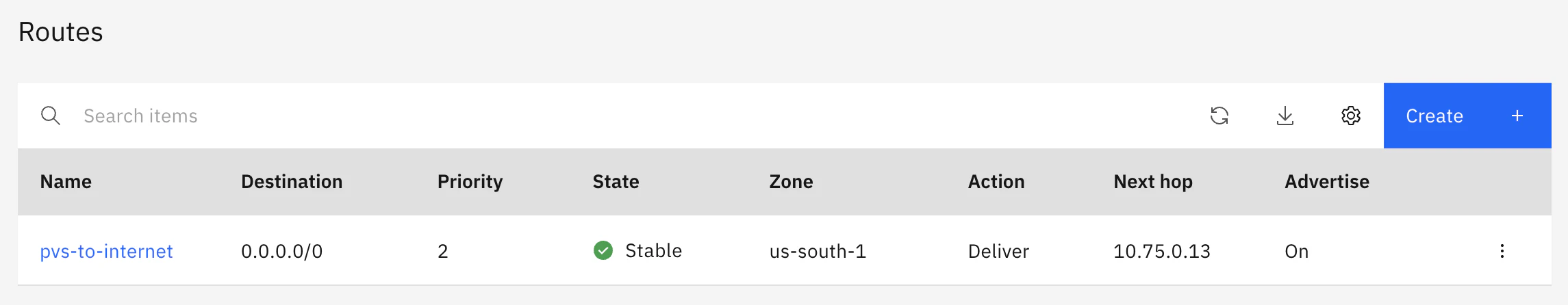
The Docs state the following: even if the active IP address of the NLB becomes unavailable due to maintenance or an outage, the routing table definition will automatically be updated to the standby address.
https://cloud.ibm.com/docs/vpc?topic=vpc-nlb-vnf&interface=ui
NLB route mode is designed to be transparent. When a failover occurs, route mode updates all routing rules created under the same VPC with the next_hop of the Standby appliance IP.
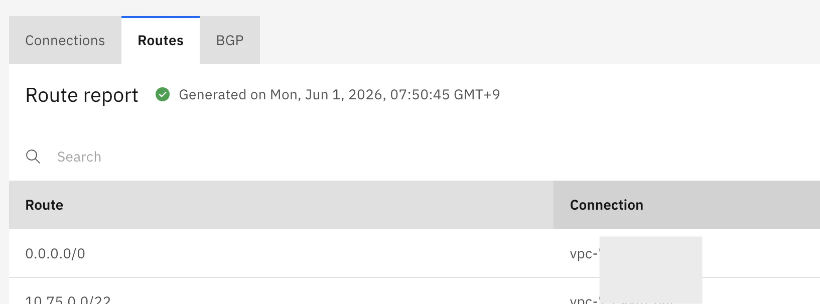
Route report on Transit Gateway
Verify that the Transit Gateway is advertising a route for 0.0.0.0/0 from the VPC.
Verify on the LPAR
Verify that communication from the LPAR to the Internet is now possible.
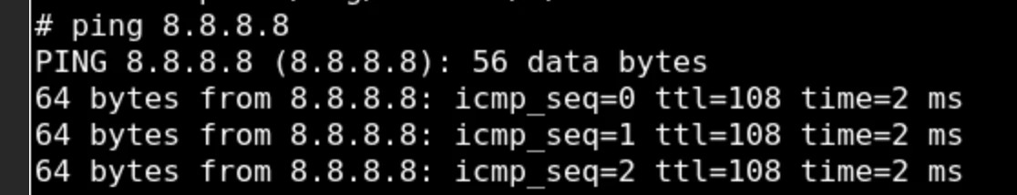
With that, outbound traffic from PowerVS to the Internet is now enabled.
I wrote about inbound communications here.