はじめに
xv6とはUnix V6のx86(32bit)実装の教育用OSです。前回の記事でxv6のソースコードリーディングをお勧めしたのですが、今回からソースコードの解説をしたいと思います! まずは、segmentationとpagingを中心としたboot処理です。
目次
- 何がOS実装の理解を難しくしているのか
- xv6実装の詳解
- boot処理編: segmentationとpagingを中心に <= 本記事はココ
- マルチタスク処理
準備
https://github.com/mit-pdos/xv6-public の準備をしておきます
# -*- mode: ruby -*-
# vi: set ft=ruby :
Vagrant.configure("2") do |config|
  config.vm.box = "ubuntu/trusty32"
  config.vm.synced_folder ".", "/home/vagrant/shared"
end
のち、vagrant up && vagrant sshでubuntuに入ったのち、
# バージョン固定せずにかなりラフにinstallしても動くようだ。本記事ではqemuは使用しないので、インストールしていない
$ sudo apt-get install build-essential gdb libgmp3-dev libmpfr-dev libmpfr4 libmpfr4-dbg mpc
$ git clone https://github.com/mit-pdos/xv6-public
$ cd shared/xv6-public
# もし、動作確認したければ、以下のようにする
$ sudo apt-get install qemu
# Makefile参考に
$ make qemu
参考リンク
-
Intel® 64 and IA-32 Architectures Software Developer’s Manual(SDM) vol.3 (Order Number: 325384-067US May 2018) (公式) 本記事では
Intel SDM vol.3と略します -
https://gist.github.com/knknkn1162/9ba537b49b10e77f39462a30b274689e boot処理の具体的なメモリ配置(詳しくはrealmodeの節を参照してください)
-
https://gist.github.com/knknkn1162/9ba537b49b10e77f39462a30b274689e bootasm.s ~ bootmain.cまでのdisassembleコード, linker map
-
https://gist.github.com/knknkn1162/53335fba4cb1221021b472557e0e027a entry.Sのdisassembleコード, linker map
-
https://gist.github.com/knknkn1162/09e9a8c12e0a4ea0db07deb1d7bb4c19 main関数以降のセグメントヘッダの情報(
readelf -l kernelで取得したもの) -
http://www.wiki.os-project.jp/ 今回レジスタやsegment descriptorをいくつか参考にするのですが、Intel SDM vol.3(公式のmanual)を見るの大変なので、実際どのような構造かを確かめる際はこのサイトが見やすいと思います。
-
https://wiki.osdev.org/Memory_Map_(x86)#Overview boot時のメモリ配置の部分が参考になる
-
http://caspar.hazymoon.jp/OpenBSD/annex/gcc_inline_asm.html インライン構文について必要十分な解説
-
http://bochs.sourceforge.net/techspec/PORTS.LST (x86 port一覧)
boot処理時(の登場人物)で混乱する
登場人物とはどういうことかというと、GDT(Global Descriptor Table),code segment,segmentation,paging,register(GDTR, cr0, cr3, esp, cs, ds..)およびその周辺の用語のことです。
pagingとsegmentationの区別とか、code segment, code segment selector, code segment register, descriptor tableの関係性で混乱してしまうとかですね。
どこまで読むかですが、pagingの設定がひと段落つくところくらいまでは通しで解説して、あとちょこちょこエピローグみたいな感じでつまんでいければ良いかなと思っています。
全体の流れ
ポイントとしては、BIOSのboot処理部分とOSのboot処理を区別しておくことと、OS開発という意味ではOSのboot処理から実際のコードを書き始めるということです。
- 電源入れる
- cs, eip registerに値がセットされて、メモリの0xFFFF0にジャンプする
- この番地にはBIOSのbootstrap codeがある。このcodeはBIOSを起動するためのプログラム(0xF0000~)に飛ぶ命令のみ入っているのでjumpする
BIOSのboot処理:
  - メモリにいろいろ設定(マッピングやら)
  - 外部機器が使用可能かチェック
  - Power On Self Test(POST)
  - ドライブの検出、ブートメディアの選択
  - 先頭セクタのデータには、OSのboot loaderが事前に書き込まれている状態で、そのデータをメモリの0x7c00にロード
OSのboot処理:
    real mode:
    bootasm.S:
      - InterruptをOFFに
      - A20 lineを解除
      - GDT(Global Descriptor Table)を設定し、その先頭アドレスをレジスタ(GDTR)にロード
      - protected modeのスイッチ(%cr0 registerのPE flag)をONにする。
      - segmentationはこの時点でONになっている。(OFFにする設定はできないことに注意)
  protected mode:
    bootasm.S:
      - %cs(code segment register), %ds(data segment register)を設定(Basic Flat Modelを構成しようとしてる)
      - %espを再設定し、bootmainに飛ぶ(つまり%eipが変化する)
    bootmain.c:
      xv6 kernelのエントリーポイントにjumpするのを目指す:
        - entry.Sの実行バイナリ(ELF形式)の先頭部分をDiskから0x10000番地~0x11000番地にロード
        - ELF headerとELF program headerからentrypointやらバイナリサイズやらの情報を引っ張ってくる
        - kernel program実行部分をDiskからロード
        - kernel programのentrypoint(entry.Sのバイナリ)に飛ぶ
    entry.S:
      - page directoryを用意し、その先頭アドレスを%cr3 registerにロード(一旦仮のものとして用意する)
      - pagingのスイッチ(%cr0 registerのPG flag)をONにする(この時点でvirtual memory addressを使用することになる)
      - スタック領域はstaticに用意されているので、%espをそのスタック領域の先頭に設定
      - main関数にjumpする
    main.c:
      kinit1():
        - page directory, page tableを再構成するための領域を4MB弱、確保
      kvmalloc():
        setupkvm()[kernel space(virtual memory)をphysical memoryに反映させるためのpage table, page directoryの再構成]:
          - page directory(4byte*1024entry)を動的に作成
          - page directoryの使用するentryだけ各々flagを設定する
          - それぞれのpage directoryのentryに対応するpage table(4byte*1024entry)を動的に作成。
          - page tableも、設定したいentryのみ、各々flagと、対応するphysical memory addressを指定する
        switchkvm():
          - setupkvmでpage directoryが再構成できたので、その先頭アドレスを%cr3 registerに再ロード
      (中略):
      seginit():
          - kernel spaceとuser spaceを権限的に分けたいのでGDTを再設定し、その先頭アドレスをレジスタ(GDTR)にロード
      (省略):
Note) 実はmain関数を見ていくとわかるのですが、xv6はmultiprocessor対応しています。
ここで、複数のCPUのboot処理ってこのフローと異なるのではないか![]() 、という疑問が出てきます。結論から言うと、BIOS bootstrapの前に、(複数あるうちの)いずれか一つのCPUで上記の処理を担当することになっています(他のCPUは、boot担当のCPUの進捗落ち着いた、っていう合図が来るまで待機しています1。そのへんから語り始めると本記事の話題に突入できなくなるので、補足にて追記しました)。なので、複数のCPUが同時に上記の処理を行なっているのではなく、1つのCPUでboot処理が上記のように走っています。
、という疑問が出てきます。結論から言うと、BIOS bootstrapの前に、(複数あるうちの)いずれか一つのCPUで上記の処理を担当することになっています(他のCPUは、boot担当のCPUの進捗落ち着いた、っていう合図が来るまで待機しています1。そのへんから語り始めると本記事の話題に突入できなくなるので、補足にて追記しました)。なので、複数のCPUが同時に上記の処理を行なっているのではなく、1つのCPUでboot処理が上記のように走っています。
real mode(からprotected modeに移行するまで)
準備
前の記事でもお話ししたように(linker mapと)実行ファイルをdisassemblyしたファイルを用意しておくと実際に割り当てられるメモリの中身がわかってイメージ掴みやすいです。
ちょっとファイルが大きいので、全体は https://gist.github.com/knknkn1162/9ba537b49b10e77f39462a30b274689e におきました。本記事では必要な箇所だけコードを切り取っているので、全体感を把握する場合はgistのほうを参考に。
# Makefileの`make bootblock`を参考にした。
$ gcc -fno-pic -static -fno-builtin -fno-strict-aliasing -O2 -Wall -MD -ggdb -m32 -Werror -fno-omit-frame-pointer -fno-stack-protector -fno-pic -O -nostdinc -I. -c bootmain.c
$ gcc -fno-pic -static -fno-builtin -fno-strict-aliasing -O2 -Wall -MD -ggdb -m32 -Werror -fno-omit-frame-pointer -fno-stack-protector -fno-pic -nostdinc -I. -c bootasm.S
## -m: Emulate the emulation linker. -N: Set the text and data sections to be readable and writable.
## -e start: Use entry as the explicit symbol for beginning execution of your program
## -Ttext 0x7C00:  Locate a section in the output file at the absolute address given by 0x7C00.
## -M: output linkermap to STDOUT
$ ld -m elf_i386 -N -e start -Ttext 0x7C00 -o bootblock.o bootasm.o bootmain.o -M
$ objdump -S bootblock.o > bootblock.asm
boot sectorからメモリの0x7c00にOS boot programがロードされて、%cs=0, %ip=0x7c00(%ipは%eipの下位16bitのregister)がセットされたところからスタートです。
real modeの概要
boot処理のはじめに動作するモードで昔々のCPUの互換性のために残っている感じで、いろいろ不便なので、融通の効くモード(protected mode)にさっさと移動します。
その条件2とは、
+ interruptをdisable
+ GDT(Global Descriptor Table) をロード
+ Physical address line A20 がキーボードを介してenableにする (  A20 line に関しては、 http://caspar.hazymoon.jp/OpenBSD/annex/gate_a20.html がわかりやすい。)
+ cr0 レジスタの最下位ビット(PE)をオン
なので、そこまでの把握。
メモリ番地について
bootblock.o:     file format elf32-i386


Disassembly of section .text:
# Start the first CPU: switch to 32-bit protected mode, jump into C.
# The BIOS loads this code from the first sector of the hard disk into
# memory at physical address 0x7c00 and starts executing in real mode
# with %cs=0 %ip=7c00.
00007c00 <start>:
最初、%ipレジスタが0x7c00なのは、リンク時に-Ttext 0x7C00としたから。本質的にはOSのboot loaderを物理メモリの0x7c00番に読み込んでいて、その番地にjumpしたからです。
InterruptをOFFに
.code16                       # Assemble for 16-bit mode
.globl start
start:
  # interruptをdisable
  cli                         # BIOS enabled interrupts; disable
    7c00:	fa                   	cli
cliはinterruptをoffするinstructionですので、一番目の条件はクリアしました。
各種レジスタを0に初期化
  # BIOS doesnot guarantee anything about the contents of %ds, %es, %ss, so set 0
  xorw    %ax,%ax             # Set %ax to zero
    7c01:	31 c0                	xor    %eax,%eax
  movw    %ax,%ds             # -> Data Segment
    7c03:	8e d8                	mov    %eax,%ds
  movw    %ax,%es             # -> Extra Segment
    7c05:	8e c0                	mov    %eax,%es
  movw    %ax,%ss             # -> Stack Segment
    7c07:	8e d0                	mov    %eax,%ss
各種レジスタを0に初期化しています。
A20 lineの解除
00007c09 <seta20.1>:
// キーボードを介して Physical address line A20 をenableにする(第3の条件)
seta20.1:
  // read the status register form the keyboard controller via the port 0x64
  inb     $0x64,%al               # Wait for not busy
    7c09:	e4 64                	in     $0x64,%al
  testb   $0x2,%al
    7c0b:	a8 02                	test   $0x2,%al
  // If input buffer is full(bit1 is set), repeat
  jnz     seta20.1
    7c0d:	75 fa                	jne    7c09 <seta20.1>

  // the CPU writes to port 0x64, the byte is interpreted as a command byte.
  // command Write output port(P2) ..0xd1
  movb    $0xd1,%al               # 0xd1 -> port 0x64
    7c0f:	b0 d1                	mov    $0xd1,%al
  outb    %al,$0x64
    7c11:	e6 64                	out    %al,$0x64

00007c13 <seta20.2>:

seta20.2:
  inb     $0x64,%al               # Wait for not busy
    7c13:	e4 64                	in     $0x64,%al
  testb   $0x2,%al
    7c15:	a8 02                	test   $0x2,%al
  jnz     seta20.2
    7c17:	75 fa                	jne    7c13 <seta20.2>

  // Command 0xdf: Enable A20 address line
  movb    $0xdf,%al               # 0xdf -> port 0x60
    7c19:	b0 df                	mov    $0xdf,%al
  // If the CPU writes to port 0x60, the byte is interpreted as a data byte.
  // suppose that It can be read/written by writing 0x20/0x60 to port 0x64 and then reading/writing a data byte from/to port 0x60.
  outb    %al,$0x60
    7c1b:	e6 60                	out    %al,$0x60
やっていることとしては、キーボードコントローラのA20 lineを解除しています(つまりenableにしてる)。A20 lineの背景に関しては、 http://caspar.hazymoon.jp/OpenBSD/annex/gate_a20.html が非常にわかりやすいです。
ここの部分のコードは外部IOとのやりとりで、いかにも低レイヤーな話で大事なんですが、本記事で説明する本質的な範囲とずれてしまうわりに、話せば長くなるトピック(I/O port周辺)なので、補足に回しました。0x64とか0x2とか$0x60とかマジックワードが気になる方は補足の「I/O portについて」を参照してください。
GDTをGDTRにロード
  // 2番目の条件
  lgdt    gdtdesc
    7c1d:	0f 01 16             	lgdtl  (%esi)
    7c20:	78 7c                	js     7c9e <readsect+0xe>

# 中略

## Global Destriptor table(8byte*3entries)
00007c60 <gdt>:
# Bootstrap GDT
.p2align 2                                # force 4 byte alignment
gdt:
  # each entry is 8 byte
  SEG_NULLASM                             # null seg 0x0000 0000 00 00 00 00
  SEG_ASM(STA_X|STA_R, 0x0, 0xffffffff)   # code segment
  SEG_ASM(STA_W, 0x0, 0xffffffff)         # data segment

## put the LGDT register(2+4byte)
00007c78 <gdtdesc>:
gdtdesc:
  # The lower 16 bits tell the size of the GDT
  .word   (gdtdesc - gdt - 1)             # sizeof(gdt) - 1
  # the upper 32 bits tell the location of the GDT in memory
  .long   gdt                             # address gdt
やってることとしては、gdtdescをGDTR(register)にロードしてます。それよりもGDTってなんぞやとかそこらへんですね。
protected modeでは、memory managementの機能としてx86では、segmentationとpagingが用意されています。segmentationはcode, dataの部分を分離するための機能、pagingは必要な分だけメモリを使用できるための機能です。3
pagingはOptionalな機能でdefaultではOFFになっているのですが、segmentationはprotected modeを有効にした瞬間からsegmentationが常にONなので(実はsegmentationの機能はOFFにすることができません4)、protected modeに入る前にあらかじめGDTを設定しておき、GDTの場所をregisterに記憶させておく必要があると言うわけです。
segmentationの設定はGDT(Global Descriptor Table)で管理します。ここで、GDTとは、最大で8192個の設定(本記事ではentryと言うことにします5)ができる配列です(一つの設定は8byteで構成されています6。 「最大」なのでそれより少ない数で構成されている分には全く構いません)
https://slideplayer.com/slide/12925813/# から適当に撮ってきました
xv6では、disassembleしたファイルを見るとGDTは0x00007c60番地に設定されています:
00007c60 <gdt>:
# Bootstrap GDT
.p2align 2                                # force 4 byte alignment
gdt:
  # each entry is 8 byte
  SEG_NULLASM                             # null seg 0x0000 0000 00 00 00 00
  SEG_ASM(STA_X|STA_R, 0x0, 0xffffffff)   # code segment
  SEG_ASM(STA_W, 0x0, 0xffffffff)         # data segment
3つ設定が書かれていますが、これは、protected modeの節の直後に説明します。
さて、lgdt gdtdescは
-
GDTの居場所(0x00007c78)と
-
GDT自体の大きさ(可変なので)
をGDTR(Global Descriptor Table Register)というregisterに保存するためのinstructionです。
GDTR
Intel SDM vol.3 Figure 2-6. Memory Management Registers から
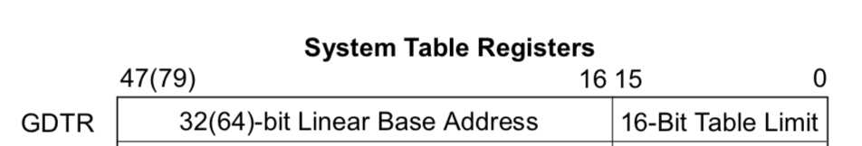
gdtdescの中身を以下のように設定しています。
## put the LGDT register(2+4byte)
00007c78 <gdtdesc>:
gdtdesc:
  # The lower 16 bits tell the size of the GDT
  .word   (gdtdesc - gdt - 1)
  # the upper 32 bits tell the location of the GDT in memory
  .long   gdt
ということで、GDT(Global Descriptor Table)およびlgdt gdtdescの意味合いがわかりました。
用語がいろいろでてきたのでまとめておくと、
+ GDT(Global Descriptor Table): entryを格納するための配列
+ GDTR(Global Descriptor Table Register): GDTの場所(先頭アドレス)とサイズを記憶しておくregister
+ 1つのentryの大きさは8byteでsegmentationの設定情報が格納されている
です。これからやること(protected modeを有効にした直後にやること)は、
+ code部分のsegmentationの情報が入っているGDT内のentryの場所を%cs(code segment register)に記憶させ
+ data部分のsegmentationの情報が入っているGDT内のentryの場所を%ds(data segment register)に記憶させる
です。
protected modeに移行
  movl    %cr0, %eax
    7c22:	0f 20 c0             	mov    %cr0,%eax
  // 4番目の条件
  // #define CR0_PE          0x00000001      // Protection Enable
  orl     $CR0_PE, %eax
    7c25:	66 83 c8 01          	or     $0x1,%ax
  movl    %eax, %cr0
    7c29:	0f 22 c0             	mov    %eax,%cr0
%cr0は以下のようなregisterです:
Intel SDM vol.3 figure2.7
および、
CR0.PE
Protection Enable (bit 0 of CR0) — Enables protected mode when set; enables real-address mode when clear. This flag does not enable paging directly. It only enables segment-level protection. To enable paging, both the PE and PG flags must be set.
とあるので、このフラグを有効にします。これで、protected modeが有効になりました![]()
protected mode
protected modeとは、x86本来の動作モードです。(x86-64ではさらにlong modeというmodeに飛びます)
ここからはmodeの変更はなく、segmentationとかpagingとかのトピックに入っていきます。現在のところ、
-
segmentation: 常に有効だが、現状未設定の部分あり
-
paging: 有効にしてない
という状態です。
bootasm.Sの残り
%cs(code segment register), %ds(data segment register)を設定
  # define SEG_KCODE 1  // kernel code
  # set %cs <- $(SEG_CODE<<3) = 0x08, which is at the 2nd GDT entry
  ljmp    $(SEG_KCODE<<3), $start32
    7c2c:	ea                   	.byte 0xea
    # %cs:($0x007c31)
    7c2d:	31 7c 08 00          	xor    %edi,0x0(%eax,%ecx,1)

00007c31 <start32>:
.code32  # Tell assembler to generate 32-bit code now.
start32:
  # define SEG_KDATA 2  // kernel data+stack
  # set %ds <- 0x10, which is the 3rd index GDT entry
  movw    $(SEG_KDATA<<3), %ax    # Our data segment selector
    7c31:	66 b8 10 00          	mov    $0x10,%ax
  movw    %ax, %ds                # -> DS: Data Segment
    7c35:	8e d8                	mov    %eax,%ds
見た目長い(実は解説も長い)のですが、code segment register, data segment registerの設定をしています。
00007c60 <gdt>:
# Bootstrap GDT
.p2align 2                                # force 4 byte alignment
gdt:
  # each entry is 8 byte
  SEG_NULLASM                             # null seg 0x0000 0000 00 00 00 00
  # #define SEG_ASM(type,base,lim)
  SEG_ASM(STA_X|STA_R, 0x0, 0xffffffff)   # code segment
  SEG_ASM(STA_W, 0x0, 0xffffffff)         # data segment
前節で、protected modeに入りましたが、segmentationの設定を引き続きしなければなりません![]()
segmentationの設定の中身を理解するために、segmentationのcodeとdataを分離する仕組みがどうなっているのかを理解する必要があります。(前節でも述べましたが、segmentationはOFFにできませんので、何らかのsegmentationの設定をする必要があります7。)
Note) 今の所、paging機能を有効にしていないので、linear addressというのは物理メモリアドレスそのものです。
図のBase addressをcode部分とdata部分で異なるようにすれば、物理メモリアドレスの領域の分離ができます。GDTのentry内にBase addressを設定できる部分があります(領域のサイズも設定する)。
GDT(Global Descriptor Table)にentryが複数あるので、どの位置にあるのかを指し示すregisterがそれぞれ%cs(code segment register), %ds(data segment register)です8。
ところが、linuxおよび、xv6では、code部分、data部分のBase addressを同じ0x00000000に指定することで、実質的にsegmentationの分離機能を打ち消してしています9。(paging機能が、memory managementの役割を担っています) 上図で言うと、"logical address"と"linear address"が全く同じになります。
ここからは、%csやそれぞれのentryの中身を見ていきましょう。
%cs, %dsの構造
%cs, %ds registerは以下のような構造をしています:
Intel SDM ch.3.4.2 Segment Selectors
-
indexとはGDTのentryのindex番号のことです。と同時にGDTの各entryは8byteですので、
index<<3(indexと言う値を左3bitずらした(*8した)値)はGDTの先頭アドレス(0x00007c31)からのoffset[byte]と解釈できます。 -
TIは0で固定
-
RPLは0b00(ここの部分は、
main()のseginit()で再設定しますのでその時に説明します。)
となります。現状では、%cs=%ds=0ですので、両者ともSEG_NULLASMのentryをさすことになっています。GDTのindex=0はnullとして扱うように定められています(null segment selectorという)。null segment selectorはどういう働きがあるかと言うと、
Attempting to load a null segment selector (see Section 3.4.2, “Segment Selectors”) into the CS or SS segment register generates a general-protection exception (#GP). A null segment selector can be loaded into the DS, ES, FS, or GS register, but any attempt to access a segment through one of these registers when it is loaded with a null segment selector results in a #GP exception being generated. Loading unused data-segment registers with a null segment selector is a useful method of detecting accesses to unused segment registers and/or preventing unwanted accesses to data segments.
Intel SDM vol.3 ch.5.4.1 Null Segment Selector Checking からの引用
とのことで、load自体はできるけど、accessするときは、きちんと適切なentryを指し示してね、ということです。そういうわけで、protected modeに入ったら一番はじめに
-
ljmp $(SEG_KCODE<<3), $start32で%csを(1<<3)のように設定し, (SEG_ASM(STA_X|STA_R, 0x0, 0xffffffff)を指し示すように) -
movw %ax, %dsで%dsを(2<<3)(SEG_ASM(STA_W, 0x0, 0xffffffff)を指し示すように)
のように設定しています。(ljmpは第一引数部分が%csregisterを設定する部分で、第二引数が%eipregisterを指定する部分です。実は、%csはmov instruction等で直接書き換えることはできません10ので、far jumpの命令を使用して%csの修正を実現しています)
GDTのentryの構造
GDTのentryの中身ですが、各entryは8byteの領域で以下のようになっています:
Intel SDM vol.3 Figure 3-8. Segment Descriptor
設定たくさんありますが、今回使用するのは、Base, limit, typeの3種のみです。 Base 31:24, Base23:16, Base address 15:00とあるのがBase addressとそのbit positionで飛び地のような形になっています。Segment limitも飛び地になっています。定義見ると以下のような形で定義されている感じ11ですね。
# define SEG_ASM(type,base,lim)                                  \
        .word (((lim) >> 12) & 0xffff), ((base) & 0xffff);      \
        .byte (((base) >> 16) & 0xff), (0x90 | (type)),         \
                (0xC0 | (((lim) >> 28) & 0xf)), (((base) >> 24) & 0xff)
typeで
# define STA_X     0x8       // Executable segment
# define STA_W     0x2       // Writeable (non-executable segments)
# define STA_R     0x2       // Readable (executable segments)
とあるように、権限指定をしています。STA_Xがある場合、(コードは実行されるため)code segmentとなり、%csで指し示す先となります。STA_Xのフラグがない場合、data segmentとなり、%dsで指し示す先となります。
残りのregisterの設定
  movw    %ax, %es                # -> ES: Extra Segment
    7c37:	8e c0                	mov    %eax,%es
  movw    %ax, %ss                # -> SS: Stack Segment
    7c39:	8e d0                	mov    %eax,%ss
  movw    $0, %ax                 # Zero segments not ready for use
    7c3b:	66 b8 00 00          	mov    $0x0,%ax
  movw    %ax, %fs                # -> FS
    7c3f:	8e e0                	mov    %eax,%fs
  movw    %ax, %gs                # -> GS
    7c41:	8e e8                	mov    %eax,%gs
additional data-segment registers (%es, %fs, %gs)とstack領域のresiter(%ss)もbase addressを0x00にするので、GDTのdata segmentのentryを指し示すようにしています。
bootmain関数にジャンプ
 # Set up the stack pointer and call into C.
  movl    $start, %esp
    7c43:	bc 00 7c 00 00       	mov    $0x7c00,%esp
  call    bootmain
    7c48:	e8 d5 00 00 00       	call   7d22 <bootmain>
..(中略)

00007d22 <bootmain>:
{
やっとbootmain.cのentrypointに飛べますね![]() スタックポインタ(%esp)を$start(0x7c00)と定めていて(使用可能領域12であるということ以外の理由はあまりありません)、スタック積むときはgrow downしていく感じです。
スタックポインタ(%esp)を$start(0x7c00)と定めていて(使用可能領域12であるということ以外の理由はあまりありません)、スタック積むときはgrow downしていく感じです。
bootmain.cでやることはkernelの実行プログラムをHDDからメモリにロードし、kernel program のentrypoint(entry.S)に飛ぶことです。
bootmain.c
ここからは、ELFの構造を既知のものとして話を進めますので、よくわからんかたは、前記事での参考リンク
ELF(Executable and Linking Format) に関しては、http://www.cirosantilli.com/elf-hello-world/ および、https://qiita.com/knknkn1162/items/c67ae7c2ef71a713adf8 を読みましょう。手を動かして確かめるのを推奨します。用語集としてbinary hacksパラパラ見るのもお勧めです。
をご覧ください。
kernelのELF binaryの先頭部分のロード
void
bootmain(void)
{
  struct elfhdr *elf;
  struct proghdr *ph, *eph;
  void (*entry)(void);
  uchar* pa;

  // ELF binary places in-memory copy at address 0x10000
  elf = (struct elfhdr*)0x10000;  // scratch space

  // Read 1st page off disk
  // void readseg(uchar* pa, uint count, uint offset)
  readseg((uchar*)elf, 4096, 0); // 4096 = 0x1000
HDDの先頭セクタにはたった今解説しているprogram code( https://gist.github.com/knknkn1162/9ba537b49b10e77f39462a30b274689e )が入っていますが、この次のsectorから、kernel program codeが入っている状態です。(セクタについては、http://softwaretechnique.jp/OS_Development/bootloader1.html が良いと思います。)
HDDからkernelのELFバイナリを物理メモリアドレスの0x10000番地~(4096=0x01000byte)分ロードします。
実は全てloadしているわけではないのですが、コレは、ELFのprogram headerとheaderさえ取得できれば、entrypointやらバイナリサイズやらの情報を引っ張ってこれるので、そうしています。
readsegに関してはHDDとのやり取りの部分ですが、real modeのA20lineの解除(こちらはキーボードコントローラが関係してる)と同様に、本質的に外部IOとのやり取りの部分なので、補足の「I/O portについて」で解説します。
program実行部分をDiskからロード
  // Load each program segment (ignores ph flags).
  // program header table offset, 0 if not present. elf->phoff=0x40(header size)
  ph = (struct proghdr*)((uchar*)elf + elf->phoff);
  // number of program header entries, 0 if not present.
  eph = ph + elf->phnum;
  for(; ph < eph; ph++){
    pa = (uchar*)ph->paddr;
    // read into physical memory
    readseg(pa, ph->filesz, ph->off);
program headerは複数持つので、loopで回して、各々のprogramの場所やサイズの情報を取得した上で、readsegでkernel programをロードしています。
entry.S以下で詳細にみますが、kernel実行バイナリのprogram headerの中身はこんな感じです。
$ readelf -l kernel

Elf file type is EXEC (Executable file)
Entry point 0x10000c
There are 2 program headers, starting at offset 52

Program Headers:
  Type           Offset   VirtAddr   PhysAddr   FileSiz MemSiz  Flg Align
  LOAD           0x001000 0x80100000 0x00100000 0x0a516 0x154a8 RWE 0x1000
  GNU_STACK      0x000000 0x00000000 0x00000000 0x00000 0x00000 RWE 0x10

 Section to Segment mapping:
  Segment Sections...
   00     .text .rodata .stab .stabstr .data .bss
   01
program headerの00番目はoffset: 0x001000, FileSiz: 0x0a516となっているので、コレをphysical address(0x00100000)にロードします。(実際にはsector単位は512byte(=0x0200)なので、HDDの0x001000 ~ 0x0b600の位置にあるものをmemoryの0x00100000番地以降にロードします。)
やっていることは上記で述べたことなのですが、まだ、entry.S以降のコードを追っていないので、そこで詳しく解説したいと思います。
.bss領域を0埋め
    if(ph->memsz > ph->filesz)
      // stosb(void *addr, int data, int cnt)
      // initialize every byte of a block of memory
      stosb(pa + ph->filesz, 0, ph->memsz - ph->filesz);
ph->memszの方が大きい場合は、大きい分を0埋めしています。こうしている理由は https://stackoverflow.com/a/31011428 を参照してください。
kernel programのentrypoint(entry.Sのバイナリ)に飛ぶ
  entry = (void(*)(void))(elf->entry);
  entry();
    # Note that `elf = (struct elfhdr*)0x10000;  // scratch space`
    # And that (char*)elf->entry - (char*)elf = 0x18
    # so the address of the `entry` variable is 0x10000 + 0x18.
    7d95:	ff 15 18 00 01 00    	call   *0x10018
elf->entryの番地は0x10018です。0x10000番地からスタートして、4+12+2+2+4=0x18byteのoffsetの位置にentryメンバがあるからです。
// see also http://refspecs.linux-foundation.org/elf/gabi4+/ch4.eheader.html
struct elfhdr {
  uint magic;  // must equal ELF_MAGIC 4byte
  uchar elf[12]; // 12byte
  ushort type; // 2 byte
  ushort machine; // 2byte
  uint version; // 4byte
  uint entry;
  uint phoff;
  uint shoff;
  uint flags;
  ushort ehsize;
  ushort phentsize;
  ushort phnum;
  ushort shentsize;
  ushort shnum;
  ushort shstrndx;
};
entryの中身は、entry.Sのentry pointのaddressが格納されていますので、entry()でentry pointまで飛びます。
entry.S
ここから、bootのprogram codeでなく、kernelのprogram codeになるので、gccでcompile, bootまでしておきます。
本節ではentry.Sのみの解析をしたいので、本節に限って最小構成のmain.cを以下のように用意してentry.Sのcompile, linkをします:
// Bootstrap processor starts running C code here.
// Allocate a real stack and switch to it, first
// doing some setup required for memory allocator to work.
//
# define PGSIZE 4096
# define NPDENTRIES 1024
# define KERNBASE 0x80000000
# define PDXSHIFT        22      // offset of PDX in a linear address
// Page table/directory entry flags.
# define PTE_P           0x001   // Present
# define PTE_W           0x002   // Writeable
# define PTE_U           0x004   // User
# define PTE_PS          0x080   // Page Size
typedef unsigned int pde_t;


__attribute__((__aligned__(PGSIZE)))
pde_t entrypgdir[NPDENTRIES] = {
  // Map VA's [0, 4MB) to PA's [0, 4MB)
  // (0) | 0x083
  // PTE_P: whether PTE is present
  // PTE_W: instructions are allowed to issue writes to the page
  // PTE_PS: enables 4Mbyte tables(when CR4.PSE is set)
  [0] = (0) | PTE_P | PTE_W | PTE_PS,
  // Map VA's [KERNBASE, KERNBASE+4MB) to PA's [0, 4MB)
  // page directory index
  [KERNBASE>>PDXSHIFT] = (0) | PTE_P | PTE_W | PTE_PS,
};

int
main(void)
{
  for(;;)
    ;
}
全体像は https://gist.github.com/knknkn1162/53335fba4cb1221021b472557e0e027a に置いています:
$ gcc -m32 -gdwarf-2 -Wa,-divide   -c -o main.o main.c
$ gcc -m32 -gdwarf-2 -Wa,-divide   -c -o entry.o entry.S
$ ld -m elf_i386 -o kernel entry.o main.o -T kernel.ld -M
$ objdump -S kernel > entry_disasm.asm
ポイントは、-T kernel.ldのように、カスタムのlinker scriptを指定しているところです。前記事で述べたように、linker scriptの代わりに、entry_disasm.asmとlinker mapを読むことでコードの把握をしていきたいと思います。
multiboot_headerとアドレスについて
kernel:     file format elf32-i386


Disassembly of section .text:

80100000 <multiboot_header>:
  // #define magic 0x1badb002
  .long magic
80100000:	02 b0 ad 1b 00 00    	add    0x1bad(%eax),%dh
  // #define flags 0
  .long flags
80100006:	00 00                	add    %al,(%eax)
  // checksum
  .long (-magic-flags)
80100008:	fe 4f 52             	decb   0x52(%edi)
8010000b:	e4                   	.byte 0xe4

8010000c <entry>:
# the entry address is 0x10000c
_start = V2P_WO(entry)
multiboot_headerと書いてある部分に関しては、https://www.gnu.org/software/grub/manual/multiboot/multiboot.html#Specification の仕様をみてください。(日本語資料だとhttp://softwaretechnique.jp/OS_Development/Tips/multi_boot.html )
それよりも、ここで議論しておきたい重要なことは、0x8010000cというアドレスに関してです。今まで、0x07c00~0x07e00の間で展開されているOSのboot codeをみましたが、このアドレスは一体何者でどこで定まったものか?
答えはkernelのELFを解析すればわかります:
$ readelf -l kernel

Elf file type is EXEC (Executable file)
Entry point 0x10000c
There are 2 program headers, starting at offset 52

Program Headers:
  Type           Offset   VirtAddr   PhysAddr   FileSiz MemSiz  Flg Align
  LOAD           0x001000 0x80100000 0x00100000 0x02000 0x03000 RWE 0x1000
  GNU_STACK      0x000000 0x00000000 0x00000000 0x00000 0x00000 RWE 0x10

 Section to Segment mapping:
  Segment Sections...
   00     .text .stab .stabstr .data .bss
   01
結論から言うと、実際のkernelのentryは0x0010000c(=PhysAddr+multiboot_headerのサイズ:0x0c)から始まります。0x8010000cはvirtual addressですが、ld(リンカ)はVirtual Addressを基準ににメモリ配置をしますので、virtual addressである0x8010000c表記となっています。しかし、pagingがONになっていないので、addressの番地はphysical addressがそのまま用いられます。なので、pagingがONになるまでは、
| virtual address | physical address |
|---|---|
| 0x80100000 | -> 0x00100000 |
| 0x8010000c | -> 0x0010000c |
のようにvirtual address表記をphysical addressに読み替えが必要です(pagingがONになった時点で、virtual addressが用いられます)。
今のお話は、リンカ・ローダ実践開発テクニックの第5章(リンカスクリプトの役割と動作)の「VMA(Virtual Memory Address)とLMA(Load Memory Address)の関係」の節にも詳しくかかれてありますので参考までに。
以下、アドレスの出所についてですが、コレはkernel.ldを見る必要があります。0x80100000は:
# https://gist.github.com/knknkn1162/53335fba4cb1221021b472557e0e027a#file-kernel-ld-L6-L12
ENTRY(_start)

SECTIONS
{
	/* Link the kernel at this address: "." means the current address */
        /* Must be equal to KERNLINK */
	. = 0x80100000;
からきている部分です。なので、entry.Sの開始番地(virtual address)が0x80100000となっています。
一方で、Physical addr: 0x00100000となっているのは、
# https://gist.github.com/knknkn1162/53335fba4cb1221021b472557e0e027a#file-kernel-ld-L14-L17
  /* specify LoadMemory Address */
	.text : AT(0x100000) {
		*(.text .stub .text.* .gnu.linkonce.t.*)
	}
からきています。
4Mbyteのpagingを許可
entry:
  # Turn on page size extension for 4Mbyte pages
  movl    %cr4, %eax
8010000c:	0f 20 e0             	mov    %cr4,%eax
# #define CR4_PSE         0x00000010      // Page size extension
  orl     $(CR4_PSE), %eax
8010000f:	83 c8 10             	or     $0x10,%eax
  movl    %eax, %cr4
80100012:	0f 22 e0             	mov    %eax,%cr4
%cr4registerにて4Mbyteのpagingも許可するフラグ(PSE)をONにします。
Intel SDM vol.3 Fig2.7 Control Registers から引用 PSE Page Size Extensions (bit 4 of CR4) — Enables 4-MByte pages with 32-bit paging when set; restricts 32-bit paging to pages of 4 KBytes when clear.
Note) コレは、pagingのサイズを4Mbyteに制限すると言うことではなく、4Kbyte pagingに加えて、4Mbyte paging も許可する というフラグです。
page directoryのaddressをレジスタにロード
  movl    $(V2P_WO(entrypgdir)), %eax
80100015:	b8 00 10 10 00       	mov    $0x101000,%eax
  movl    %eax, %cr3
8010001a:	0f 22 d8             	mov    %eax,%cr3
entrypgdir変数はmain関数の中にglobalに定義されているので、それを参照しています:
// alignしている理由は、Intel SDM vol.3 ch.2.5 CONTROL REGISTERS に
/*
CR3 — Contains the physical address of the base of the paging-structure hierarchy and two flags (PCD and PWT).
Only the most-significant bits (less the lower 12 bits) of the base address are specified;
the lower 12 bits of the address are assumed to be 0.
The first paging structure must thus be aligned to a page (4-KByte) boundary.
The PCD and PWT flags control caching of that paging structure in the processor’s internal data caches
(they do not control TLB caching of page-directory information).
*/
// とあるから。
__attribute__((__aligned__(PGSIZE))) # PGSIZE=4096=0x1000=4Kbyte
pde_t entrypgdir[NPDENTRIES] = {
  // Map VA's [0, 4MB) to PA's [0, 4MB)
  // (0) | 0x083
  // PTE_P: whether PTE is present
  // PTE_W: instructions are allowed to issue writes to the page
  // PTE_PS: enables 4Mbyte tables(when CR4.PSE is set)
  [0] = (0) | PTE_P | PTE_W | PTE_PS,
  // Map VA's [KERNBASE, KERNBASE+4MB) to PA's [0, 4MB)
  // page directory index
  [KERNBASE>>PDXSHIFT] = (0) | PTE_P | PTE_W | PTE_PS,
};
Intel SDM vol.3 Fig4.6 Linear-Address Translation to a 4-MByte Page using 32-Bit Paging
pagingをONにした瞬間、Physical memoryからVirtual memoryに切り替わるので、pagingを有効にする前にPage Directoryを用意し13、その先頭アドレスの値を%cr3 registerにセットして、Page Directoryの居場所を反映させます14。(%cr3はこの用途に用いられるため、Page Directory Base Register(PDBR)とも呼ばれています。)
Page Directoryは4byte*1024entry(=4096byte)もつ領域で、それぞれのentryの構造は以下のようになっています:
Intel SDM vol.3 Figure 4-4. Formats of CR3 and Paging-Structure Entries with 32-Bit Paging より引用 PDE: 4MB pageの部分の設定を参照すること
(0) | PTE_P | PTE_W | PTE_PSと言う部分に関しては、
| flag | Bit Position(0~31) | contents |
|---|---|---|
| PTE_P | 0 | Present; must be 1 to map a 4-KByte page |
| PTE_W | 1 | Read/write; if 0, writes may not be allowed to the 4-MByte page |
| PTE_PS | 7 | Page size; must be 1 (otherwise, this entry references a page table |
| addr | 31:22 | Bits 31:22 of physical address of the 4-MByte page referenced by this entry |
なので15、R/Wが1になっている状態であり、virtual address(0x80000000~)をphysical address(0x00000000~)にmappingしています。
後ほどPTE_Uも使うので説明しておくと、supervisorでなくともpageの中身を使用できると言うフラグです。
しかしながら、すぐ後のmain関数のkvmalloc()でpagingの再設定、再ロードを行います。(pagingがONになってからswitchkvm()が終わるまではこの4M-byte pagingの設定が有効です。)
Note) 上の例のmappingだと、xv6のkernel space(0x80000000~0x803FFFFFF: 4MB)においては、
0x80000000 = 0b1000 0000 00   00 0000 0000 0000 0000 0000
            Directory index ^       Offset(22bit=4MB)
なので、
virtual address(0x80000000~0x803FFFFFF)をphysical address(0x00000000~0x003FFFFFF)にmappingさせるために、Page Tableのindex=0b1000 0000 00(=256)の位置のentryの31:22bitを0x0(physical addressの31:22bit目)と設定しています。このentryの21:0bitは各種flag(&reserved)です。
Offset(0x00000000 ~ 0x003FFFFF)の部分がphysical addressに反映されるので4MBの連続した領域がmappingされるというわけです。
paging機能をONに
  # Turn on paging.
  movl    %cr0, %eax
8010001d:	0f 20 c0             	mov    %cr0,%eax
# #define CR0_PG          0x80000000      // Paging
# #define CR0_WP          0x00010000      // Write Protect
  orl     $(CR0_PG|CR0_WP), %eax
80100020:	0d 00 00 01 80       	or     $0x80010000,%eax
  movl    %eax, %cr0
80100025:	0f 22 c0             	mov    %eax,%cr0
ここで、paging機能をONにします。%cr0は以下の通り(実はprotected modeをONにするときも登場(PE flag)しました):
CR0.PG .. Paging(bit 31 of CR0) —Enables paging when set; disables paging when clear. When paging is disabled, all linear addresses are treated as physical addresses. The PG flag has no effect if the PE flag (bit 0 of register CR0) is not also set; setting the PG flag when the PE flag is clear causes a general-protection exception (#GP).
WP(Write Protect)は、Intel SDM vol.3によれば、
CR0.WP
Write Protect (bit 16 of CR0) — When set, inhibits supervisor-level procedures from writing into read- only pages; when clear, allows supervisor-level procedures to write into read-only pages (regardless of the U/S bit setting; see Section 4.1.3 and Section 4.6). This flag facilitates implementation of the copy-on- write method of creating a new process (forking) used by operating systems such as UNIX.
と言うことで、read-onlyのものをkernelレベルで書き込むようにする特別な理由はないので、ONにしています。
main関数にjump!!
  movl $(stack + KSTACKSIZE), %esp
80100028:	bc 00 30 10 80       	mov    $0x80103000,%esp
  # Jump to main(), and switch to executing at
  # high addresses. The indirect call is needed because
  # the assembler produces a PC-relative instruction
  # for a direct jump.
  # mov    $0x80100034,%eax
  mov $main, %eax
8010002d:	b8 34 00 10 80       	mov    $0x80100034,%eax
  jmp *%eax
80100032:	ff e0                	jmp    *%eax

int
main(void)
{
80100034:	55                   	push   %ebp
あとは、bootasm.sとおんなじ感じで%espにstack pointerを定めて、main.cのmain関数にjumpします。
main.c
前節でmain関数を変更したので、xv6のmain関数に戻しておきます。
# Makefile使用する
make kernel
# objdump -S kernel > xv6_kernel.asm
readelf -s kernel > kernel_readelf_s.log
kernel_readelf_s.logは https://gist.github.com/knknkn1162/09e9a8c12e0a4ea0db07deb1d7bb4c19 に置いときました。
kinit1()
kinit1(end, P2V(4*1024*1024)); // phys page allocator
page directory, page tableを再構成するための領域を4MB弱、使用可能状態(free)にしています。
第一引数のendはlinker scriptの https://github.com/mit-pdos/xv6-public/blob/master/kernel.ld#L63 で定められていて、addressは、0x801144a8 ( https://gist.github.com/knknkn1162/09e9a8c12e0a4ea0db07deb1d7bb4c19#file-kernel_readelf_s-log-L291 )となりました。P2V(4*1024*1024)は2GB+4MB=(0x80400000)なので、
0x80115000~0x80400000までの領域を使用可能状態にしておくことになります。(開始アドレスが切り上げられているのは、 https://github.com/mit-pdos/xv6-public/blob/b818915f793cd20c5d1e24f668534a9d690f3cc8/kalloc.c#L50 のため。
なので、4MB弱といったのはこう言う理由からでした。
さて、kinit1の中身を追っていくと、kinit1()->freerange()->kfree()です。freerange()の引数に、freeにするaddressの始端と終端を設定します。ループでkfree()が呼ばれ、PGSIZE(=0x1000=4096byte)ごとにfreelistに追加されていきます。
また、kfree関数は以下のようになっています:
struct run {
  struct run *next;
};

struct {
  struct spinlock lock;
  int use_lock;
  struct run *freelist;
} kmem;

void
kfree(char *v)
{
  struct run *r;

  if((uint)v % PGSIZE || v < end || V2P(v) >= PHYSTOP)
    panic("kfree");

  // Fill with junk to catch dangling refs.
  memset(v, 1, PGSIZE);

  # if(kmem.use_lock)
  #   acquire(&kmem.lock);
  r = (struct run*)v;
  r->next = kmem.freelist;
  kmem.freelist = r;
  # if(kmem.use_lock)
  #  release(&kmem.lock);
}
ここで、現在のところ、interruptがOFFになっており(real modeの一番最初にcliinstructionがあった。まだinterruptを有効状態に戻していない16)、CPUも今の所1つでdead lockはおきませんので、acquire, releaseは不要です。そのため、kinit1()の内部でkmem.use_lock=0となっています。(なので、自分の方でコメントアウトしておきました)
kfreeが一回呼ばれた後と、2回呼ばれた後の図です。
アドレス勘違いしてますが、先頭は0x80107000でなく0x80115000が正しいです
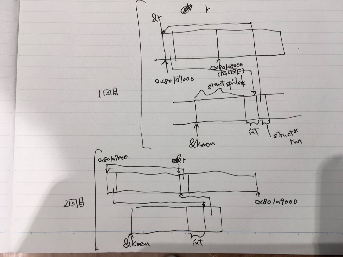
これを繰り返すと、0x80115000から0x80400000までのkinit()の結果、
kmem.freelist <- &[0x80115000 ~ 0x80116000] <- &[0x80116000 ~ 0x80117000] <- ... <- &[0x80399000 ~ 0x80400000] <- kmem.freelist <- ...
なので、単方向循環リストですね!
pagingのpage tableとpage directoryの再設定がまだなので、次のkvmalloc()で行うことにします。(page directory, page tableをkallocするだけの領域を使用可能にした)
Note) pagingとalloc/freeの関係について。
pagingが有効になっている時、addressはvirtual addressが使用されるので、どのように実際のphysical addressに変換したらいいのかをhardware側に伝える必要があります。なので、もし、pagingが設定されていない領域のvirtual addressを使用した時、hardware例外(page-fault exceptions(#PF))が発生します17。
一方で、alloc/freeの場合は、software上で使用できる/できないの管理をしているだけです。なので、もし、freeされていない領域にアクセスした場合は(pagingの設定が適切である限り)、hardware側が何かしてくれるわけではなく、OS側(software側)で例外を発生させるなり、イベント起こすなりする必要があります。
実際に領域を確保する処理とpagingは全く別物です。pagingの設定はあくまでvirtual addressからphysical addressへのmappingを与えるだけです。領域の確保状況はalloc/freeが管理します。なので、このkinit1の例だと、
  movl    $(V2P_WO(entrypgdir)), %eax // [0x80000000>>PDXSHIFT] = (0) | PTE_P | PTE_W | PTE_PS
  movl    %eax, %cr3
  // このすぐ後にpaging のflagをONにする
でpagingを%cr3(Page Directory Base Register(PDBR))に再ロードさせてから、kinit1でfree(領域を使用可能状態に)していることになります。
kvmalloc()
4K-byte pagingについて
main.cのkvmalloc()で行うことは、pagingの再設定と%cr3 register(Page Directory Base Register:PDBR)への再ロードです。
注意) kvmalloc()のswitchkvm()でpage directoryの再ロードをするまでは、現行のpage mapping
__attribute__((__aligned__(PGSIZE)))
pde_t entrypgdir[NPDENTRIES] = {
  // Map VA's [0, 4MB) to PA's [0, 4MB)
  // (0) | 0x083
  // PTE_P: whether PTE is present
  // PTE_W: instructions are allowed to issue writes to the page
  // PTE_PS: enables 4Mbyte tables(when CR4.PSE is set)
  [0] = (0) | PTE_P | PTE_W | PTE_PS,
  // Map VA's [KERNBASE, KERNBASE+4MB) to PA's [0, 4MB)
  // page directory index
  [KERNBASE>>PDXSHIFT] = (0) | PTE_P | PTE_W | PTE_PS,
};
が適用されています。
ここで、pagingの仕組みについて触れたいと思います。再設定するものとしては、4K byteのpagingで、以下のようなイメージになります:
Intel SDM vol.3 Fig4.2より引用 Note) [前節](https://qiita.com/knknkn1162/items/cb06f19e1f999bf098a1#cscode-segment-register-dsdata-segment-register%E3%82%92%E8%A8%AD%E5%AE%9A)で解説した通りsegmentationの設定より、virtual address=linear addressとなっています。
前節で解説した通りsegmentationの設定より、virtual address=linear addressとなっています。virtual addressの下位12bit=(4Kbyte)がそのままphysicall addressの下位12bitになるため、4K byteは物理メモリ上で連続した領域になります。そういうわけで、pageの単位が4K byteとなります。
Note) 4M byteのpagingのままにしない理由としては、効率的にメモリ領域を使えないからです。4M byteのpagingだと、ある未使用のメモリ領域を使用する(alloc)際、たとえ、10KBしか使わずとも、4M byteの領域をガバッと使用中状態に切り替えることになります。これは資源の無駄なので、4K byte単位というある程度小さな単位でメモリ領域の使用状態を変更できるようにしたい、と言うモチベーションがあります。つまり使用する分だけ4K byte*(数単位)分の領域を確保していろいろプログラムを動かすというオペレーションになっています。
4M-byte pagingと違い、間に新たにpage tableというのが挟まっています。
ある部分の領域が必要になったら必要な分だけ新規にpage tableを動的に作成し..みたいなことをします(下図):
Figure 4-13. Memory Management Convention That Assigns a Page Table to Each Segment より一部引用 Note) PTE: Page Table Entry, PDE: Page Directory Entryのこと
Page Tableで空白になっているentryは使用されていない箇所で、もしここが使用されるようになったら、page tableのentryの設定flagを修正することになります。page tableもpage directoryのように4byte*1024entryの配列構造になっています。と言うことで、それぞれの構造は以下のようになります:
Intel SDM vol.3 Figure 4-4. Formats of CR3 and Paging-Structure Entries with 32-Bit Paging より引用 PDE: page tableとPTE: 4KB pageの列を参照のこと。
page tableのentryの設定内容は4M byte pagingで紹介した時と同じような感じです。
xv6のメモリ配置
前の記事の補足でもちらっと触れたのですが、xv6のメモリ配置は以下のようになります:
https://pdos.csail.mit.edu/6.828/2018/xv6/book-rev11.pdf の Figure 2-2. を引用
xv6では、kernel spaceに関しては、virtual address <=> physical addressの変換公式を以下のように決めています:
# define V2P(a) (((uint) (a)) - KERNBASE)
# define P2V(a) ((void *)(((char *) (a)) + KERNBASE))
kallocでmappingする領域は、
| idx | virtual address | physical address |
|---|---|---|
| 0 | 0x80000000 ~ 0x80100000 | 0x00000000 ~ 0x00100000 |
| 1 | 0x80100000 ~ 0x80107000 | 0x00100000 ~ 0x00107000 |
| 2 | 0x80107000 ~ 0x8E000000 | 0x00107000 ~ 0x0E000000 |
| 3 | 0xFE000000 ~ 0xFFFFFFFF | 0x7E000000 ~ 0x7FFFFFFF |
です。
kernel spaceとuser spaceのpaging
(![]() ここちょっと難しいです)
ここちょっと難しいです)
pagingというと、下図のように、mappingを動的に決めるイメージを持っているかもしれません:
http://www.cse.iitm.ac.in/~chester/courses/16o_os/slides/5_Processes.pdf のslide p24から引用
異なる複数のprocessで同じprogramを走らせる場合、部分的に 同じphysical addressの領域を指し示すようにpagingを設定するといった具合に。(これはpagingの一つの利点で、全く同じ部分を別の領域に複数もつことがなくなり、メモリの省力化につながる)
なんで、kernel spaceでは変換公式が決め打ちなのでしょうか?
実は、kernel spaceのpagingを設定する際は、全てのprocessで同じvirtual address <=> physical addressの変換公式が使用されます。
全てのprocessのkernel spaceのprogram codeは同じなので、全てのprocessのmappingを同じにすることでcodeのshareを意図しています。(kernelにもstack(data領域)はあり、これらはそれぞれのprocessによって異なるものですが、user processと異なり、kernel spaceに滞在する時間が(system callの呼び出しでkernel spaceに入るパターンとかを例にとれば)短いため、それほど問題ないのでしょう18)
user spaceに関しては、上に述べたような、あらかじめ決められたmappingの設定はありません。
例えば、main関数のuserinit()ではinitcode.Sの実行バイナリをuser spaceにmappingするのですが、その場合は、kallocで使用可能な領域を確保した上で、以下のコードのinituvmのように、
virtual addressの[0~4096byte)の user space を[V2P(mem), V2P(mem)+4096)にmappingしています。
(と同時に[mem, mem+4096)の kernel space は[V2P(mem), V2P(mem)+4096)にmappingされています。ややこしいですね![]() )
)
# define V2P(a) (((uint) (a)) - KERNBASE)
// Load the initcode into address 0 of pgdir.
// sz must be less than a page.
void
inituvm(pde_t *pgdir, char *init, uint sz)
{
  char *mem;

  if(sz >= PGSIZE)
    panic("inituvm: more than a page");
  mem = kalloc();
  memset(mem, 0, PGSIZE);
  // PTE_W: writable, PTE_U: user
  // mappages(pde_t *pgdir, void *va, uint size, uint pa, int perm)
  // PGSIZE
  mappages(pgdir, 0, PGSIZE, V2P(mem), PTE_W|PTE_U);
  memmove(mem, init, sz);
}
必要事項はだいたい説明したので、kvmalloc()の動作を見ていきたいと思います:
kvmalloc()の動作
kmap変数にて、virtual addressのどの領域からphysical addressのどの領域までmappingするのか定められています。
// This table defines the kernel's mappings, which are present in
// every process's page table.
static struct kmap {
  void *virt;
  uint phys_start;
  uint phys_end;
  int perm;
} kmap[] = {
 // #define EXTMEM=0x00100000
 // ##define KERNBASE 0x80000000         // First kernel virtual address
 { (void*)KERNBASE, 0,             EXTMEM,    PTE_W}, // I/O space (0x80000000 ~ 0x80100000)
 // #define KERNLINK (KERNBASE+EXTMEM)=0x80100000  // Address where kernel is linked
 { (void*)KERNLINK, V2P(KERNLINK), V2P(data), 0},     // kern text+rodata (0x80100000 ~ 0x80107000)
 { (void*)data,     V2P(data),     PHYSTOP,   PTE_W}, // kern data+memory (0x80107000 ~ 0x8E000000)
 // #define DEVSPACE 0xFE000000         // Other devices are at high addresses
 { (void*)DEVSPACE, DEVSPACE,      0,         PTE_W}, // more devices (0xFE000000 ~ 0xFFFFFFFF)
};
| idx | virtual address | physical address |
|---|---|---|
| 0 | 0x80000000 ~ 0x80100000 | 0x00000000 ~ 0x00100000 |
| 1 | 0x80100000 ~ 0x80107000 | 0x00100000 ~ 0x00107000 |
| 2 | 0x80107000 ~ 0x8E000000 | 0x00107000 ~ 0x0E000000 |
| 3 | 0xFE000000 ~ 0xFFFFFFFF | 0x7E000000 ~ 0x7FFFFFFF |
kmap変数内のdata変数はまたまた、kernel.ldで定義されていて、
	/* Adjust the address for the data segment to the next page */
	. = ALIGN(0x1000);
	PROVIDE(data = .);
こんな感じになっており、0x1000byte単位でアライメントされることになっています。
実際のdataのaddressは https://gist.github.com/knknkn1162/09e9a8c12e0a4ea0db07deb1d7bb4c19#file-kernel_readelf_s-log-L371 から 0x80107000とわかります(linker mapを作って確認しても良いです)。
kvmallocがやっていることは、各々のidxに対して、virtual addressからphysical addressに変換させるためのpage mappingの作成です。
例として、idxが0の0x80000000 ~ 0x80100000の領域のpage mappingを作成することを考えます。
0x80000000 = 0b1000 0000 00   00 0000 0000   0000 0000 0000
             Directory index ^ Table index ^   Offset
なので、だいたい以下のような実装になります:
1: page directoryの領域(4byte1024entry)を確保する(初回のみ)
2: virtual address: 0x80000000~0x80001000(4096byte)領域の場合、page directoryのindex=512(0x80000000の上位10bit)のentryが使用されているかどうか確認する(PTE_P: Presennt のフラグを見ることで判断できる)
3: 使用されていなければ、page tableの領域(4byte1024entry)を新規確保し(これは4096byte=0x1000でalignmentされてる)、page directoryのindexが31:22bit目(=512)のentryの中身を(今確保したpage tableのaddress)|PTE_P|PTE_W|PTE_Uのように設定する19。
4: page tableのindex=0(これは0x80000000の22:12bit目(=0))のentryの中身を(physical address) | PTE_Pとする。この場合、0x00000000+PTE_Pになる。
5: 2に戻って virtual address: 0x80001000~0x80002000の場合..., virtual address: 0x80002000~0x80003000の場合..., のようにして、2~4を繰り返す。
上記の領域を確保(alloc)するというのは、main関数のkinit1(end, P2V(4*1024*1024))で使用可能にした領域 の範囲で、という意味です。現在設定しようとしているpage mappingと混乱しないように。
もう一つ例をあげると、例えば、virtual address: 0x80100000 ~ 0x80101000のpage mappingを作成したい場合、
0x80100000 = 0b1000 0000 00   01 0000 0000   0000 0000 0000
             Directory index ^ Table index ^   Offset
なので、
1: 作成済み
2: 使用されているので3は飛ばして4へ
4: page tableのindex=256(0x80100000の22:12bit目)のentryの中身を(physical address: 0x00100000) | PTE_Pとする。
5: addressを+0x1000だけincrementして4の作業を行う
と言うような感じになります。ポイントとしては、page directoryのentryのAddress of page tableはallocするときにaddressが定められます。
一方で、page tableのentryのAddress of 4KB frameの方は先ほど述べた変換公式に基づいて、上記のaddressを決定します。
kvmalloc -> setupkvm -> mappages -> walkpgdirと辿っていき、本質的な部分はwalkpgdir関数が仕事している感じです。
switchkvm()
残りの部分は非常に簡単で、先ほど再構成したpage directoryの先頭アドレスを%cr3 registerに反映させるだけです。レジスタに入れるaddressはvirtual addressでなく、physical addressであることだけ注意です。
void
switchkvm(void)
{
  // set CR3 register
  lcr3(V2P(kpgdir));   // switch to the kernel page table
}
ここまで来て、setupkvm()で設定した、新しいpagingの設定が反映されます![]()
kalloc関数を用いて、領域を使用できることになります。
seginit()
real modeからprotected modeに移行するためにGDT(Global Descriptor Table)を定めました。
これからはuser landで動作するprocessをmain関数のuserinit()以下で作りに行きたいので、kernel spaceとuser spaceの権限とを分けて行きたいです。そのために、GDT(Global Descriptor Table)の再定義とGDTRへの再ロードを行います。
GDTの再定義
void
seginit(void)
{
  struct cpu *c;

  // Map "logical" addresses to virtual addresses using identity map.
  // Cannot share a CODE descriptor for both kernel and user
  // because it would have to have DPL_USR, but the CPU forbids
  // an interrupt from CPL=0 to DPL=3.
  c = &cpus[cpuid()];
ここは、multiprocessorを意識しています。各CPUごとの情報を格納しているのがstruct cpuで
struct cpu {
  uchar apicid;                // Local APIC ID
  struct context *scheduler;   // swtch() here to enter scheduler
  struct taskstate ts;         // Used by x86 to find stack for interrupt
  // #define NSEGS     6
  struct segdesc gdt[NSEGS];   // x86 global descriptor table
  volatile uint started;       // Has the CPU started?
  int ncli;                    // Depth of pushcli nesting.
  int intena;                  // Were interrupts enabled before pushcli?
  struct proc *proc;           // The process running on this cpu or null
};
のようになっています。今回設定するのはgdt memberだけなのですが、他のメンバーについてはswitchingの記事の際にがっつり説明するのでお楽しみ~
  c->gdt[SEG_KCODE] = SEG(STA_X|STA_R, 0, 0xffffffff, 0);
  c->gdt[SEG_KDATA] = SEG(STA_W, 0, 0xffffffff, 0);
  // #define DPL_USER    0x3     // User DPL
  c->gdt[SEG_UCODE] = SEG(STA_X|STA_R, 0, 0xffffffff, DPL_USER);
  c->gdt[SEG_UDATA] = SEG(STA_W, 0, 0xffffffff, DPL_USER);
}
Intel SDM vol.3 Fig3.8を引用 DPL (descriptor privilege level) field .. Specifies the privilege level of the segment. The privilege level can range from 0 to 3, with 0 being the most privileged level. The DPL is used to control access to the segment. See Section 5.5, “Privilege Levels”, for a description of the relationship of the DPL to the CPL of the executing code segment and the RPL of a segment selector.
あとはGDTのentryの設定。gdtのindex=0はnull segmentとして予約されていて、index=1,2がkernel space, index=3,4がuser spaceです。後者では、DPL_USER flagを指定しています。ここのフラグはsystem callの呼び出しやinterrupt発生の際に効いてくるのですが、schedulerの挙動の記事の時に再度お話ししたいと思います!
GDTをGDTRにロード
lgdt(c->gdt, sizeof(c->gdt));
lgdt関数は
static inline void
lgdt(struct segdesc *p, int size)
{
  volatile ushort pd[3];

  pd[0] = size-1;
  pd[1] = (uint)p;
  pd[2] = (uint)p >> 16;

  asm volatile("lgdt (%0)" : : "r" (pd));
}
ですが、やってることはreal modeでのGDTRのロードと同じです。asm keywordについては、http://caspar.hazymoon.jp/OpenBSD/annex/gcc_inline_asm.html が良記事です。
まとめ
ながーい記事でしたが、お疲れ様でした![]()
![]() あんまりうまく説明できてないかもしれませんが、死ぬほど詳しく書いたつもりです
あんまりうまく説明できてないかもしれませんが、死ぬほど詳しく書いたつもりです![]()
さて、今まで説明した中で大きな比率を占めてきたsegmentationとpagingについてまとめておきます:
Intel SDM vol.3 Figure 3-1. Segmentation and Paging
-
segmentationについては、上図のSegment base addressが0x0であるので、実質的にsegmentationの分離機能を打ち消している状態で、privilege(DPL)のflagだけを活用している。
-
paging(4K byte)では、page directoryあるいはpage tableを作成、あるいはentryの内容を埋めることで、virtual addressからphysical addressへのmappingを可能にします。また、alloc/free(OS上)で領域を使用できるか否かの管理を行います。
Intel SDMのdocumentは全体図がごちゃっとしがちで、逆に混乱することが多いのですが、今回segmentation, pagingを把握したことでだいぶん見えやすくなったのではないでしょうか?
補足
I/O portについて
I/O portとは、外部のデバイス(peripheral device)とのデータの出入り口のことです。ここで、I/O portのアクセスはx86では2種類提供されていて、
-
I/O-mapped I/O(separate I/O)
-
memory-mapped I/O
があります20。どちらもアドレスを用いてアクセスできるのですが、前者では、memoryとIO空間(0x0000 ~ 0xFFFFまで)が分離しており、
http://www.kumikomi.net/archives/2003/05/10kumi.php?page=27 から引用
Note) 図ではI/O 空間が0xFFまでとなっていますが、0xFFFFまでと読み替えてください。メモリ空間についても、32bitなので、0xFFFF_FFFFです。
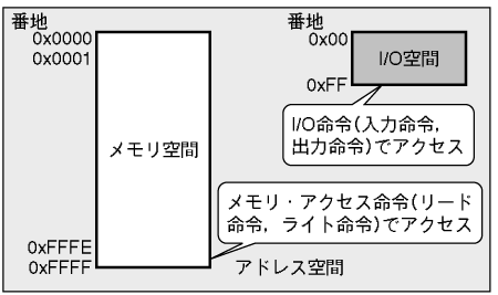
キーボード(0x60 ~ 0x64)、 HDD(いくつかあるが、primaryは0x01F0 ~ 0x01F7), グラフィック表示(VGA: 0x03D0 ~ 0x03DF)など。
x86のport一覧については、http://bochs.sourceforge.net/techspec/PORTS.LST にあります。
後者では、memoryにI/O addressがmappingされています。
http://www.kumikomi.net/archives/2003/05/10kumi.php?page=27 から引用
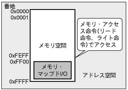
IOAPIC(I/O Advanced Programmable Interrupt Controller: defaultでは0x0FEC0000にmappingされる), Local APIC(defaultでは0x0FEE0000にmappingされる)ではmemory-mapped I/Oを介してやり取りします。
もうちょっと詳細な図については、色々徘徊しましたが、https://www61.atwiki.jp/kumikomi-yitjc/pages/12.html の冒頭の図が視覚的にわかりやすいかなと思います。
本記事ではキーボード, HDDとのやりとりなので、前者についてですが、device->CPUへの入力をin, CPU->deviceへの出力をout instructionでやり取りします:
(後者のmemory mapped I/Oの場合、in, out instructionで外部IOとのやりとりをおこなうのでなく
A20 lineの解除
基本的に、 http://bochs.sourceforge.net/techspec/PORTS.LST を参考に、port番号とcommandやdataのinput/outputをやり取りします。
A20 lineの解除に関連するコードは以下のようでした:
seta20.1:
  # read the status register form the keyboard controller via the port 0x64
  inb     $0x64,%al               # Wait for not busy
  testb   $0x2,%al
  # If input buffer is full(bit1 is set), repeat
  jnz     seta20.1

  movb    $0xd1,%al               # 0xd1 -> port 0x64
  outb    %al,$0x64

seta20.2:
  inb     $0x64,%al               # Wait for not busy
  testb   $0x2,%al
  jnz     seta20.2
  # Command 0xdf: Enable A20 address line
  movb    $0xdf,%al               # 0xdf -> port 0x60
  # sngl  enable address line A20
  outb    %al,$0x60
input buffer fullのチェック
seta20.1:
  # read the status register form the keyboard controller via the port 0x64
  inb     $0x64,%al               # Wait for not busy
  testb   $0x2,%al
  # If input buffer is full(bit1 is set), repeat
  jnz     seta20.1
port 0x64を見ると、KB controller read statusでbit 1 = 1 input buffer full (input 60/64 has data for 8042)とあるとおり、下位2bit目がON担っていれば、inputを受け付けられないので、受け付けるまで(下位2bit目がOFFになるまで) do-whileしています。
Write output port
  movb    $0xd1,%al               # 0xd1 -> port 0x64
  outb    %al,$0x64
0064	w	KB controller input buffer (ISA, EISA)
		KB controller commands (data goes to port 0060):
... 省略
		 D1	dbl   write output port. next byte written  to 0060
			      will be written to the 804x output port; the
			      original IBM AT and many compatibles use bit 1 of
			      the output port to control the A20 gate.
と書いてあるので、$0xd1をport 0x64に書き込みます。この後、port 0x60にA20 lineを解除するbitを設定するのですが、またinput buffer fullか否かを確認しています:
seta20.2:
  inb     $0x64,%al               # Wait for not busy
  testb   $0x2,%al
  jnz     seta20.2
A20 lineの解除
  # Command 0xdf: Enable A20 address line
  movb    $0xdf,%al               # 0xdf -> port 0x60
  # sngl  enable address line A20
  outb    %al,$0x60
最後に、port 0x60にDF sngl enable address line A20 (HP Vectra only???)とある通り、A20 lineを解除するbitを設定しています。
このように、ソフトウェア開発のプログラミングに慣れている方にとっては、結構独特ですが、I/O-mapped I/Oの場合は、in, out instructionでperipheral deviceとのやりとりをします
(memory-mapped I/Oの場合は直接memory addressにデータを書き込んだりすることで、やりとりを行います。例えば、https://github.com/mit-pdos/xv6-public/blob/b818915f793cd20c5d1e24f668534a9d690f3cc8/lapic.c#L48 など)
readseg
kernelのELF binaryの先頭部分のロードのreadseg関数の全体像はこんな感じ:
void
waitdisk(void)
{
  // Wait for disk ready.
  // send command to port 0x1F7
  while((inb(0x1F7) & 0xC0) != 0x40)
    ;
}

// Read a single sector at offset into dst.
void
readsect(void *dst, uint offset)
{
  // Issue command.
  waitdisk();
  //   asm volatile("out %0,%1" : : "a" (data), "d" (port));
  // Number of sectors to read/write (0 is a special value).
  // The kernel has been written to the boot disk contiguously starting at sector 1.
  outb(0x1F2, 1);   // count = 1
  // This is CHS / LBA28 / LBA48 specific.
  outb(0x1F3, offset);
  // 	Partial Disk Sector address.(0)
  outb(0x1F4, offset >> 8);
  outb(0x1F5, offset >> 16);
  // Send 0xE0 for the "master"
  outb(0x1F6, (offset >> 24) | 0xE0);
  outb(0x1F7, 0x20);  // cmd 0x20 - read sectors

  // Read data.
  waitdisk();
  // input doubleword * SECTSIZE/4 bytes from 0x1F0 into dst
  insl(0x1F0, dst, SECTSIZE/4);
}

// Read 'count' bytes at 'offset' from kernel into physical address 'pa'.
// Might copy more than asked.
void
readseg(uchar* pa, uint count, uint offset)
{
  uchar* epa;

  epa = pa + count;

  // Round down to sector boundary.
  pa -= offset % SECTSIZE;

  // Translate from bytes to sectors; kernel starts at sector 1.
  offset = (offset / SECTSIZE) + 1;

  // If this is too slow, we could read lots of sectors at a time.
  // We'd write more to memory than asked, but it doesn't matter --
  // we load in increasing order.
  for(; pa < epa; pa += SECTSIZE, offset++)
    readsect(pa, offset);
}
readsectでHDDからmemoryにSECTSIZE=512byteごとにdataを読み込んでいます。0x1F0 ~ 0x1F7のportを用いてHDDとのやりとりを行なっています。
ここで、inb関数はinb instructionをC言語に移植したもの、outb関数も同様です。(中身を見ると、asm keywordが使われているのですが、http://caspar.hazymoon.jp/OpenBSD/annex/gcc_inline_asm.html がわかりやすいです)
前節と似たような感じなので、http://bochs.sourceforge.net/techspec/PORTS.LST や https://wiki.osdev.org/ATA_PIO_Mode#Registers を参考に確かめてみてください![]()
Multiprocessorの場合のboot処理詳細
#今日のメモ MultiProcessor Initialization reset vectorに飛ぶとこまで pic.twitter.com/w5yjCPcqAB
— knknkn26918 (@knknkn26918) September 16, 2018
#今日のメモ MultiProcessor Initialization 2つのCPUがスケジューリング処理を行う直前まで pic.twitter.com/8LwraurIz9
— knknkn26918 (@knknkn26918) September 16, 2018
ここら辺、メモが汚いので記事にしたいのですが、意外とboot処理の分量多くなっちゃったので、余力があるかどうか..
-
他のCPUはbootしているCPUからstartup Inter Processor Interruptが来るまで待機します(この待機状態のことをwait-for-SIPI stateと呼びます。
Intel SDM vol.3 Ch.8.4.3 MP Initialization Protocol Algorithm for MP Systemsを参照のこと) 然るべき時と言うのは、具体的にはstartother()関数から呼び出されるhttps://github.com/mit-pdos/xv6-public/blob/e559fd2c5acdb5c3faea2d12c038b52308017ed1/lapic.c#L158 の部分に当たります。補足の「Multiprocessorの場合のboot処理詳細」に下書きですが図解を載せました。 ↩ -
https://wiki.osdev.org/Protected_Mode#Entering_Protected_Mode を参考にしました。あるいは、
Intel SDM vol.3 ch.9.9.1 Switching to Protected Modeはかなり詳細に書かれてます。 ↩ -
Intel SDM vol.3 3.1 MEMORY MANAGEMENT OVERVIEWの冒頭を参考にした ↩
-
Intel SDM vol.3 ch.3.1 MEMORY MANAGEMENT OVERVIEWに
There is no mode bit to disable segmentation. The use of paging, however, is optional.とあります。 ↩ -
このentryのことを、segment descriptorと言います。もうちょっと正確に言うと、GDT(Global Descriptor Table)には5種類のdescriptor(実際にlinuxやxv6で使用されるdescritorはsegment descriptor, TSS(Task state segment) descriptorの2種類です)を入れることができます。TSS(Task state segment) descriptorはinterruptの際に登場するので、本記事では、segment descriptorしか登場しません。なので、segment descriptorのことを単純にentryと言うことにしています。あとは、segment descriptorと
%cs(code segment register)などの用語が紛らわしいかなと思ったので、あまりsegment descriptorと言う用語を使わない方が混乱しなくて良いかな、と個人的に思いました。 ↩ -
p2align(4byte alignment)が必要な旨はIntel SDM vol.3 ch.3.5.1 Segment Descriptor Tables の最後に記載されています。 ↩
-
cs, dsの両方の設定をする必要がある旨はIndel SDM vol.3 3.2.1 Basic Flat Modelに
To implement a basic flat memory model with the IA-32 architecture, at least two segment descriptors must be created, one for referencing a code segment and one for referencing a data segment (see Figure 3-2).と書いてある。 ↩ -
Intel SDM fig.3.4には、Seg. selector(segment selector)とありますが、これは
%csや%dsのVisible Partの部分(16bit)です。Figure 3-7. Segment Registersに図があるのですが、%csや%dsは16bitの領域なのですが、%csや%dsは頻繁に変更されるレジスタではありませんので、hardwareの範囲でBase AddressやLimitをcacheとして抱えています(hidden part, shadow registerとも)。この部分はsoftware上では直接変更することができません。なので、OSプログラミングする上では、shadow registerの部分は無視してもらって、%csや%ds(総称してsegment registerとも言います)とsegment selectorをイコールとしてしまって問題ありません。以上、ややこしい話をしましたが、%cs,%dsは16bitです。 ↩ -
このsegmentationの設計のことをBasic Flat Modelと言います。Intel SDM vol.3 3.2.1 Basic Flat Modelに記述があります。 ↩
-
と言うのも、次のinstructionへのアドレスは%eipと%csに依存しているので、%csのみを変えてしまうと、%eipが変化していなくても、予期せぬアドレスへとjumpしてしまう可能性があるからです。 ↩
-
汎用的なsegment descriptorの定義は https://github.com/mit-pdos/xv6-public/blob/b818915f793cd20c5d1e24f668534a9d690f3cc8/mmu.h#L43-L46 にあります。 ↩
-
4M-byte pagingではpaging directoryをmemory領域に用意する旨はIntel SDM vol.3 ch9.8.3 Initializing Paging に記述がある。(4M-pagingの場合は、page tableを用意する必要がないのはIntel SDM vol.3 Figure4.3を見れば明らかだが、同じくch9.8.3に4M-byte pagingの場合は用意しなくて良いと書いてある) ↩
-
%cr3のpage-directory-baseには12~31bitしか格納する場所がないのですが、同じ節にCR3 — Contains the physical address of the base of the paging-structure hierarchy and two flags (PCD and PWT). Only the most-significant bits (less the lower 12 bits) of the base address are specifiedと書いてあるので、そのままのaddressを突っ込みます(ビットシフトしません) ↩ -
Intel SDM vol.3 Table 4-4. Format of a 32-Bit Page-Directory Entry that Maps a 4-MByte Page を参照してcontentsを埋めています。 ↩
-
Intel SDM vol.3 ch 4.7PAGE-FAULT EXCEPTIONS を参照のこと ↩
-
多分.. ↩
-
今回kernel spaceしか考えていないので、PTE_Uは不要だが、page tableを設定するときにPTE_Uのflagの有無により特権を持たないユーザー(一般user)で使用するかしないかを決めるようにしている。xv6のソースコードのコメントでも,
The permissions here are overly generous, but they can be further restricted by the permissions in the page table entries, if necessary.と書いてある。 ↩ -
Intel SDM vol.1 ch18.1 I/O PORT ADDRESSINGを参考にしました ↩