記事の内容
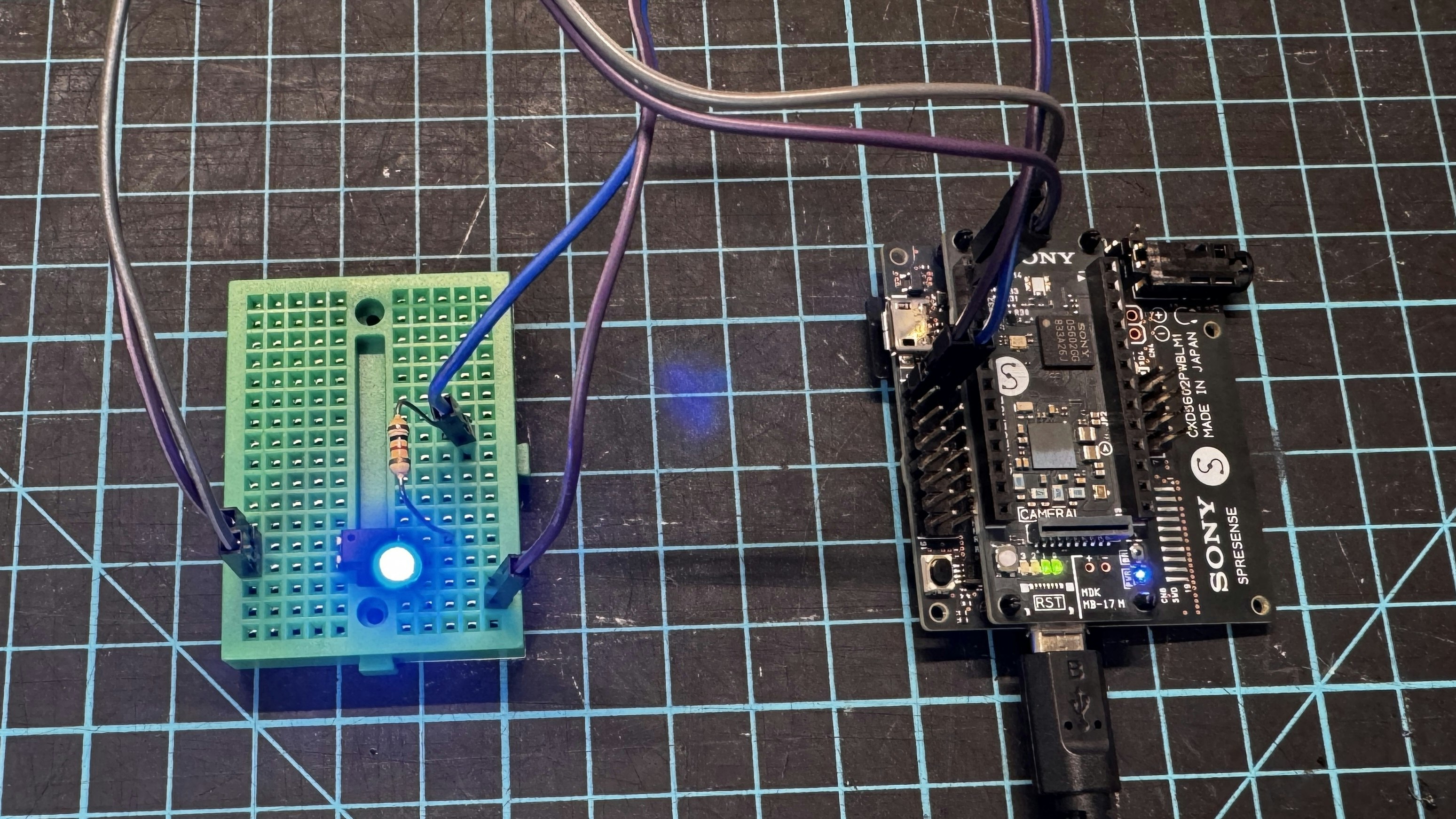
- SPRESENSEによるフォトカプラによる外部LED点灯

※写真の抵抗は手持ちのものを取り合えず使用しており、適当です。
-
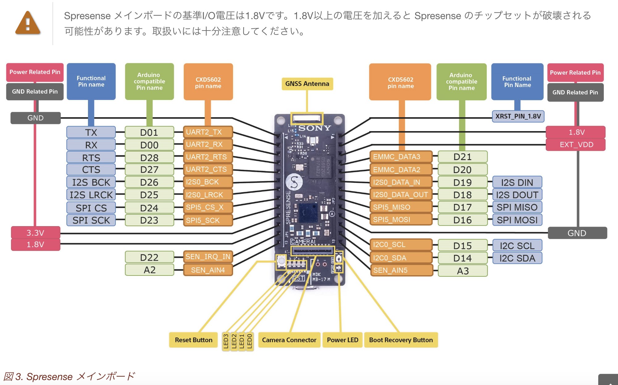
Spresense ハードウェアについて
- ※メインボードの基準I/O電圧は1.8Vです。1.8V以上の電圧を加えるとチップセットが破壊される可能性があります。取扱いには十分注意してください。

外部LEDをONOFF制御
ハードウエアのセットアップ
- SpresenseのI/Oは1.8Vなので、フォトカプラを使って外部のLEDを制御する。
- LEDの電源はLTE拡張ボードのMAIN POWER(5.0V)から供給した。

-
フォトカプラ PS817 (PC817互換品:今回はこちらを使った)
- 追記:こちらはON抵抗が50Ω程度あった。
LED点灯スケッチ
LED点灯スケッチ
LED点灯
void setup() {
  // put your setup code here, to run once:
  pinMode(1,OUTPUT);
  pinMode(LED0, OUTPUT);
  pinMode(LED1, OUTPUT);
}

void loop() {
  // put your main code here, to run repeatedly:
  digitalWrite(1,HIGH);
  digitalWrite(LED0, HIGH);
  digitalWrite(LED1, HIGH);
  delay(2000);
  digitalWrite(1,LOW);
  digitalWrite(LED1, LOW);
  delay(2000);

}
動作検証
実行できると、本体のLED0が点灯。
LED1と外部のLEDが2秒間隔で点滅します。


以上
参考
-
- SONY SpresenseのLED制御(Lチカ)サンプル
- SONY Spresenseで位置情報取得サンプル

