はじめに
M5StickVの基本はMicroPythonのMaixPyの利用です。MicroPythonを使ってM5StickV(K210)で簡単にAIを体験、利用することができます。
ただ、限られたリソースでハードウェアを使いこなそうとすると、C++を使いたい場合があるかもしれません。M5StickVはMaixCubeとは兄弟みたいなものなのでMaixシリーズ同様にArduino/Maixduino開発環境が使ってみましょう。
Maixduino
MaixCubeでも、Maixシリーズ用のArduino開発環境Maixduinoを使ってみましょう。
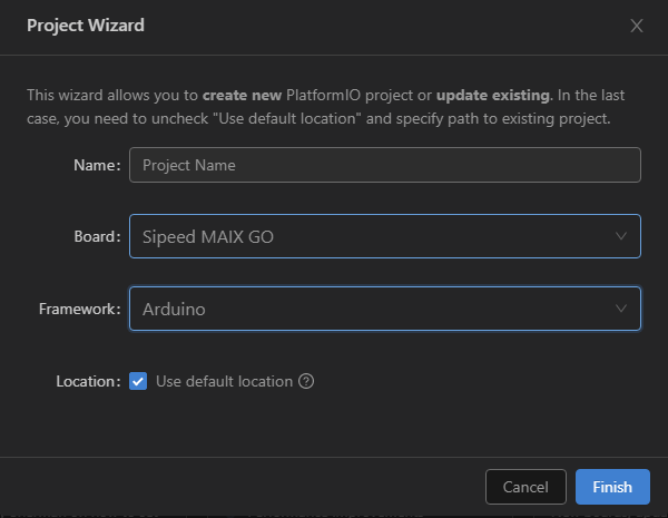
PlatformIOを使い、「+ New Project」新規プロジェクトを作成を選択し、
ボードに「Sipeed MAIX GO」を選択すれば、M5StickVでもある程度利用できます。
サンプルアプリ
-
カメラは、OV7740というセンサーが使われていて、MaixCubeと同じです
-
SPIは、Maixシリーズが8bitのインターフェースに対して、M5StickVでは1bitのシリアルです。Maixduino標準のSipeed_ST7789のライブラリーではなくTFT_eSPIを使用してみました
# include <Arduino.h>
# include <TFT_eSPI.h>
# include <Maixduino_OV7740.h>
# include <Wire.h>

# ifdef M5STICKV
# define AXP192_ADDR 0x34
# define PIN_SDA 29
# define PIN_SCL 28
# endif

TFT_eSPI lcd;
//OV7740 supports YUV only
Maixduino_OV7740 camera(FRAMESIZE_QVGA, PIXFORMAT_YUV422);

bool axp192_init() {
    Serial.printf("AXP192 init.\n");
    sysctl_set_power_mode(SYSCTL_POWER_BANK3,SYSCTL_POWER_V33);

    Wire.begin((uint8_t) PIN_SDA, (uint8_t) PIN_SCL, 400000);
    Wire.beginTransmission(AXP192_ADDR);
    int err = Wire.endTransmission();
    if (err) {
        Serial.printf("Power management ic not found.\n");
        return false;
    }
    Serial.printf("AXP192 found.\n");

    // Clear the interrupts
    Wire.beginTransmission(AXP192_ADDR);
    Wire.write(0x46);
    Wire.write(0xFF);
    Wire.endTransmission();
    Wire.beginTransmission(AXP192_ADDR);
    Wire.write(0x23);
    Wire.write(0x08); //K210_VCore(DCDC2) set to 0.9V
    Wire.endTransmission();
    Wire.beginTransmission(AXP192_ADDR);
    Wire.write(0x33);
    Wire.write(0xC1); //190mA Charging Current
    Wire.endTransmission();
    Wire.beginTransmission(AXP192_ADDR);
    Wire.write(0x36);
    Wire.write(0x6C); //4s shutdown
    Wire.endTransmission();
    Wire.beginTransmission(AXP192_ADDR);
    Wire.write(0x91);
    Wire.write(0xF0); //LCD Backlight: GPIO0 3.3V
    Wire.endTransmission();
    Wire.beginTransmission(AXP192_ADDR);
    Wire.write(0x90);
    Wire.write(0x02); //GPIO LDO mode
    Wire.endTransmission();
    Wire.beginTransmission(AXP192_ADDR);
    Wire.write(0x28);
    Wire.write(0xF0); //VDD2.8V net: LDO2 3.3V,  VDD 1.5V net: LDO3 1.8V
    Wire.endTransmission();
    Wire.beginTransmission(AXP192_ADDR);
    Wire.write(0x27);
    Wire.write(0x2C); //VDD1.8V net:  DC-DC3 1.8V
    Wire.endTransmission();
    Wire.beginTransmission(AXP192_ADDR);
    Wire.write(0x12);
    Wire.write(0xFF); //open all power and EXTEN
    Wire.endTransmission();
    Wire.beginTransmission(AXP192_ADDR);
    Wire.write(0x23);
    Wire.write(0x08); //VDD 0.9v net: DC-DC2 0.9V
    Wire.endTransmission();
    Wire.beginTransmission(AXP192_ADDR);
    Wire.write(0x31);
    Wire.write(0x03); //Cutoff voltage 3.2V
    Wire.endTransmission();
    Wire.beginTransmission(AXP192_ADDR);
    Wire.write(0x39);
    Wire.write(0xFC); //Turnoff Temp Protect (Sensor not exist!)
    Wire.endTransmission();

    fpioa_set_function(23, (fpioa_function_t)(FUNC_GPIOHS0 + 26));
    gpiohs_set_drive_mode(26, GPIO_DM_OUTPUT);
    gpiohs_set_pin(26, GPIO_PV_HIGH); //Disable VBUS As Input, BAT->5V Boost->VBUS->Charing Cycle

    msleep(20);
    return true;
}

void setup() {
    Serial.begin(115200);
    axp192_init();

    /* LCD init */
    lcd.begin();
    lcd.setRotation(1);

    /* DVP init */
    Serial.printf("DVP init\n");
    if (!camera.begin()) {
        Serial.printf("camera init fail\n");
        while (true) {}
    } else {
        Serial.printf("camera init success\n");
    }
    camera.run(true);
}

void loop() {
    uint8_t *img = camera.snapshot();
    if (img == nullptr || img == 0) {
        Serial.printf("snap fail\n");
        return;
    }

    lcd.pushImage(0, 0, camera.width(), camera.height(), (uint16_t*)img);
}
Ktool
Ktoolでフラッシュメモリに書き込む場合の、platformio.iniの設定はMaix-Goなどと同じです。
; PlatformIO Project Configuration File
;
;   Build options: build flags, source filter
;   Upload options: custom upload port, speed and extra flags
;   Library options: dependencies, extra library storages
;   Advanced options: extra scripting
;
; Please visit documentation for the other options and examples
; https://docs.platformio.org/page/projectconf.html

[env:m5stickv]
platform = kendryte210
board = sipeed-maix-go
framework = arduino

monitor_speed = 115200
upload_flags =
    -a
    0
    -B
    goE
upload_command = $PROJECT_PACKAGES_DIR/ktool/ktool.py $UPLOAD_FLAGS $SOURCE
まとめ
M5StickVでもArduino互換の開発環境が準備できました。
デフォルトのファームウェアはv0.4.0-52-g3b8c18b84-dirtyというものが入っていました。元に戻す場合のご参考。
MicroPython v0.4.0-52-g3b8c18b84-dirty on 2019-10-21; M5Stick-V with Kendryte K210

