はじめに
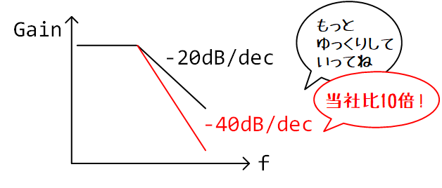
もっと波形をなまらせたい
「僕たちはもう…1次LPFでは満足できないんだ!」
そんなときは、2次LPFを使いましょう。

微分方程式を立てる
ここでは、波形をなまらせるために、下図のような2次LPFを使います1。

上図から、2次LPFの出力電圧が満たすべき式として、次の連立微分方程式が得られます2。
\begin{cases}
\displaystyle \frac{dV_1}{dt}= -\frac{2}{RC}V_1 + \frac{1}{RC}V_\mathrm{out} + \frac{1}{RC}V_\mathrm{in}\\
\displaystyle \frac{dV_\mathrm{out}}{dt}= \frac{1}{RC}V_1 - \frac{1}{RC}V_\mathrm{out}
\end{cases}
状態方程式3っぽく書くと、次のようになります。
\begin{align}
\begin{bmatrix}
\dot{V}_1\\
\dot{V}_\mathrm{out}\\
\end{bmatrix}
=
\frac{1}{RC}
\begin{bmatrix}
-2 & 1\\
1 & -1
\end{bmatrix}
\begin{bmatrix}
V_1\\
V_\mathrm{out}
\end{bmatrix}
+
\frac{1}{RC}
\begin{bmatrix}
1\\
0
\end{bmatrix}
V_\mathrm{in}
\end{align}
微分方程式の解析解を求める
先ほどの微分方程式は、大学の教科書に書かれているような解法を使えば、手計算で解くことができます……が、時間に追われる現代人にそんな余裕はないでしょう。そのため、ここでは、Wolfram Cloudを使って解を求めることにします4。
eqns ={
V1'[t]==(-2*V1[t]+Vout[t]+Vin)/tau,
Vout'[t]==(V1[t]-Vout[t])/tau,
V1[0]==V10,Vout[0]==Vout0
}
sol = DSolve[eqns, {V1,Vout},t]
Collect[(V1/.sol[[1]])[t],{Vin,V10,Vout0},Simplify]
Collect[(Vout/.sol[[1]])[t],{Vin,V10,Vout0},Simplify]
上記のコマンドをWolfram Cloud上で実行すると、次の解析解が得られます。ただし、テキスト表示の都合上、$V_1(0)$ をV10、$V_\mathrm{out}(0)$ をVout0と書いています。
2次LPFの内部電圧 $V_1(t)$

2次LPFの出力電圧 $V_\mathrm{out}(t)$

1次LPFの出力電圧の解析解はシンプルでしたが、2次LPFの場合は、ちょっと複雑です。この解析解をそのままモデルに書くのはしんどいので、考え方を変えましょう。今回は、「方程式の解ではなく、方程式そのものをモデルに組み込んで、シミュレーション実行時に逐次的に出力電圧を求めればいいや」と考えることにします。
微分方程式を離散時間で近似する
微小時間 $dt$ の代わりに、有限の短さの時間ステップ $\Delta t$ を使って、微分方程式を次のように近似します。
\begin{cases}
\displaystyle \frac{\Delta V_1}{\Delta t}= -\frac{2}{RC}V_1 + \frac{1}{RC}V_\mathrm{out} + \frac{1}{RC}V_\mathrm{in}\\
\displaystyle \frac{\Delta V_\mathrm{out}}{\Delta t}= \frac{1}{RC}V_1 - \frac{1}{RC}V_\mathrm{out}
\end{cases}
上式の両辺に $\Delta t$ を掛けると、時間ステップごとの電圧の変化量 $\Delta V_1$ と $\Delta V_\mathrm{out}$ が得られます。これを利用して、$k$ 番目の時間ステップにおける内部電圧 $V_1[k]$ と出力電圧 $V_\mathrm{out}[k]$ を次のように表します5。
\begin{cases}
\displaystyle V_1[k+1] = V_1[k] + \left(-\frac{2}{RC}V_1[k] + \frac{1}{RC}V_\mathrm{out}[k] + \frac{1}{RC}V_\mathrm{in}[k]\right) \Delta t\\
\displaystyle V_\mathrm{out}[k+1] = V_\mathrm{out}[k] + \left(\frac{1}{RC}V_1[k] - \frac{1}{RC}V_\mathrm{out}[k]\right) \Delta t
\end{cases}
SystemVerilogで記述する
先ほど得られた差分方程式をもとに、SystemVerilogで2次LPFの動作モデルを記述します。
module LPF2 #(
  parameter realtime timestep = 100ps,
  parameter real initial_vc1 = 0,
  parameter real initial_vc2 = 0,
  parameter real R = 1e3,
  parameter real C = 500e-15
)(
  input real VIN,
  input real VSS,
  output real VOUT
);
  timeunit 1s;
  timeprecision 1ps;

  real _vin;
  assign _vin = VIN - VSS;

  event initial_step;
  initial begin
    #0;
    -> initial_step;
  end

  event start_timer;
  event stop_timer;
  event next_step;

  always @(start_timer, stop_timer) begin
    if (start_timer.triggered()) begin
      fork begin
        #(timestep);
        -> next_step;
      end join_none
    end else begin // stop_timer
      disable fork;
    end
  end

  localparam realtime tau = R*C;
  realtime t;
  realtime last_t;
  realtime delta_t;
  real last_vin;
  real vc1;
  real vc2;
  real delta_vc1;
  real delta_vc2;

  always @(initial_step, next_step) begin
    if (initial_step.triggered()) begin
      vc1 = initial_vc1;
      vc2 = initial_vc2;
      last_vin = _vin;
      last_t = $realtime();
      -> start_timer;
    end else begin
      -> stop_timer;
      t = $realtime();
      delta_t = t - last_t;
      delta_vc1 = (-2*vc1 + vc2 + last_vin)*delta_t/tau;
      delta_vc2 = (vc1 - vc2)*delta_t/tau;
      vc1 += delta_vc1;
      vc2 += delta_vc2;
      last_vin = _vin;
      last_t = t;
      -> start_timer;
    end
  end

  assign VOUT = vc2 + VSS;

endmodule
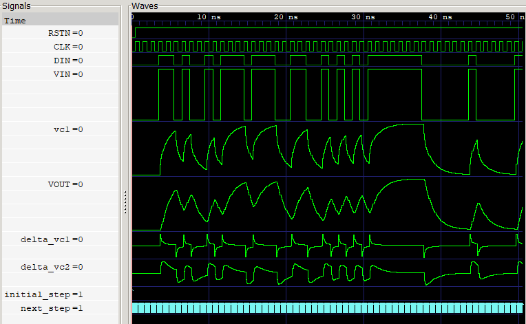
シミュレーション結果
- Simulator: ModelSim ALTERA STARTER EDITION vsim 10.5b Simulator 2016.10 Oct 5 2016
- Viewer: GTKWave Analyzer v3.3.71
おわりに
最終回じゃないぞよ
もうちっとだけ続くんじゃ
-
2次LPFの出力電圧は2階微分方程式で書き表せます。2階微分方程式を解くためには、初期条件が2つ必要になります。2次LPFにおいて初期条件としてすぐに思いつくのは、コンデンサの初期電圧がゼロという条件、すなわち $V_1(0)=0$ と $V_\mathrm{out}(0)=0$ の2つです。シミュレーション実行時に、これらの初期条件を使って計算を進めたいので、$V_1$ と $V_\mathrm{out}$ を状態変数にしています。 ↩
-
Wolfram Cloudでは、無料でWolfram言語が使えます。複雑な計算をおこないたい場合は、WolframAlphaよりもWolfram Cloudのほうが便利です。 ↩
-
これは「前進オイラー法」と呼ばれる、微分方程式の数値解法のなかで最も素朴な方法です。精度が必要な場合は、少し式がややこしくなりますが、ルンゲクッタ法を使ったほうがいいと思います。なお、前進オイラー法、ルンゲクッタ法は、どちらも陽解法に分類されます。SPICEなどの回路シミュレータでは安定性の理由から、陽解法ではなく陰解法が使われます。しかしながら、「数値解の安定性が気になるようなきわどい回路解析をVerilog simulator上でやろう」なんてことを考える人はそうそういないはずなので、実装の簡単さを優先して陽解法を採用するのがいいんじゃないかな、と何となく思っています。 ↩
