はじめに
Wio LTE Cat M1/NB1向けのGroveセンサー/アクチュエータ使い方集です。
センサー一覧
- Grove - 光センサー
- Grove - 水センサー
- Grove - 水分センサー
- Grove - 温湿度センサ(SHT31)
- Grove - 衝突センサー
- Grove - 傾きセンサー
- Grove - ラインファインダー
- Grove - 音センサー & ラウドネスセンサー
- Grove - 心拍センサー
- Grove - PIRモーションセンサー
- Grove - RGB LED
- Grove - 温湿度・気圧センサ(BME280)
- Grove - IMU 10DOF v2.0
- Grove - スライドボリューム
- Grove - LEDバー v2.0
- Grove - ジョイスティック
- Grove - マイクロスイッチ
- I2C接続小型LCDモジュール 8x2行(AQM0802A)
アナログセンサー
Wio LTE Cat M1/NB1の接続ポートはA4、またはA6です。
サンプルコードはA4に接続しています。
以下のセンサーはアナログ値が取得することが出来ます。
- 光センサー
Wikiページ: http://wiki.seeedstudio.com/Grove-Light_Sensor/ - スライドボリューム
Wikiページ: http://wiki.seeedstudio.com/Grove-Slide_Potentiometer/ - 水分センサー
Wikiページ: http://wiki.seeedstudio.com/Grove-Moisture_Sensor/
# include <WioCellLibforArduino.h>

WioCellular Wio;
int sensorPin = WIO_A4;
int sensorValue = 0;

void setup() {
    SerialUSB.begin(115200);
    Wio.Init();
    Wio.PowerSupplyGrove(true);
    delay(200);
    pinMode(sensorPin,INPUT_ANALOG);
}
void loop() {
    sensorValue = analogRead(sensorPin);
    SerialUSB.print("Value = " );
    SerialUSB.println(sensorValue);
    delay(500);
}
デジタル(スイッチ系)センサー
Wio LTE Cat M1/NB1の接続ポートはD38、またはD20です。
サンプルコードはD38に接続しています。
以下センサーはデジタル(ON/OFF)が取得することが出来ます。
- 傾きセンサー
Wikiページ: http://wiki.seeedstudio.com/Grove-Tilt_Switch/ - マイクロスイッチ
Wikiページ: https://www.seeedstudio.com/Grove-Micro-Switch-p-3033.html
# include <WioCellLibforArduino.h>

WioCellular Wio;
int sensorPin = WIO_D38;

void setup() {
    SerialUSB.begin(115200);
    pinMode(sensorPin, INPUT);
}
void loop() {
    const int sensorValue = digitalRead(sensorPin);
    SerialUSB.print("Value = " );
    SerialUSB.println(sensorValue);
    delay(500);
}
水センサー
Wio LTE Cat M1/NB1の接続ポートはD38、またはD20です。
サンプルコードはD38に接続しています。
Wikiページ: http://wiki.seeedstudio.com/Grove-Water_Sensor/
# include <WioCellLibforArduino.h>

# define WATER_SENSOR WIO_D38

void setup() {
  SerialUSB.begin(115200);
  pinMode(WATER_SENSOR, INPUT);
}
void loop() {
  if (digitalRead(WATER_SENSOR) == 0) {
    SerialUSB.println("WATER adhesion");
  }
  delay(500);
}
Wio LTE Cat M1/NB1の接続ポートはI2Cです。
温湿度センサ(SHT31)
Wikiページ: http://wiki.seeedstudio.com/Grove-TempAndHumi_Sensor-SHT31/
# include <WioCellLibforArduino.h>
# include <Wire.h>
# include "SHT31.h"  // https://github.com/Seeed-Studio/Grove_SHT31_Temp_Humi_Sensor

WioCellular Wio;
SHT31 sht31 = SHT31();

void setup() {
  SerialUSB.begin(115200);
  Wio.Init();
  Wio.PowerSupplyGrove(true);
  delay(500);
  sht31.begin();
}
void loop() {
  float temp = sht31.getTemperature();
  float hum = sht31.getHumidity();
  SerialUSB.print("Temp = ");
  SerialUSB.print(temp);
  SerialUSB.println(" C"); //The unit for  Celsius because original arduino don't support speical symbols
  SerialUSB.print("Hum = ");
  SerialUSB.print(hum);
  SerialUSB.println("%");
  SerialUSB.println();
  delay(1000);
}
衝突センサー
Wio LTE Cat M1/NB1の接続ポートはD38、またはD20です。
サンプルコードはD38に接続しています。
Wikiページ: http://wiki.seeedstudio.com/Grove-Collision_Sensor/
# include <WioCellLibforArduino.h>

# define COLLISION_SENSOR WIO_D38

WioCellular Wio;

void setup() {
    SerialUSB.begin(115200);
    pinMode(COLLISION_SENSOR,INPUT);
}
void loop() {
  if(isTriggered()) {
    SerialUSB.println("Collision");
    delay(2000);
  } else {
    SerialUSB.println("Free");
  }
}
bool isTriggered() {
  if(!digitalRead(COLLISION_SENSOR)) {
    delay(50);
    if(!digitalRead(COLLISION_SENSOR)) {
      return true; //the collision sensor triggers
    }
  }
  return false;
}
ラインファインダー
Wio LTE Cat M1/NB1の接続ポートはD38、またはD20です。
サンプルコードはD38に接続しています。
Wikiページ: http://wiki.seeedstudio.com/Grove-Line_Finder/
# include <WioCellLibforArduino.h>

WioCellular Wio;

const int signalPin = WIO_D38;

void setup()   {
  SerialUSB.begin(115200);
  pinMode(signalPin, INPUT);
}
void loop() {
  if(HIGH == digitalRead(signalPin)) {
    SerialUSB.println("black");
  } else {
    SerialUSB.println("white");
  }
  delay(1000);
}
音センサー & ラウドネスセンサー
Wio LTE Cat M1/NB1の接続ポートはA4、またはA6です。
サンプルコードはA4に接続しています。
Wikiページ: http://wiki.seeedstudio.com/Grove-Sound_Sensor/
Wikiページ: http://wiki.seeedstudio.com/Grove-Loudness_Sensor/
# include <WioCellLibforArduino.h>

WioCellular Wio;
const int pinAdc = WIO_A4;

void setup(){
  SerialUSB.begin(115200);
  Wio.Init();
  Wio.PowerSupplyGrove(true);
  pinMode(pinAdc,INPUT_ANALOG);
}
void loop(){
  long sum = 0;
  for(int i=0; i<32; i++){
    sum += analogRead(pinAdc);
  }

  sum >>= 5;

  SerialUSB.println(sum);
  delay(10);
}
心拍センサー
Wio LTE Cat M1/NB1の接続ポートはD38、またはD20です。
サンプルコードはD38に接続しています。
Wikiページ: http://wiki.seeedstudio.com/Grove-Ear-clip_Heart_Rate_Sensor/
# include <WioCellLibforArduino.h>

WioCellular Wio;

# define HEART_SENSOR_PIN  WIO_D38

boolean led_state = LOW;//state of LED, each time an external interrupt will change the state of LED
unsigned char counter;
unsigned long temp[21];
unsigned long sub;
bool data_effect=true;
unsigned int heart_rate;//the measurement result of heart rate

const int max_heartpluse_duty = 2000;//you can change it follow your system's request.
                        //2000 meams 2 seconds. System return error
                        //if the duty overtrip 2 second.
void setup()
{
  SerialUSB.begin(115200);
  delay(200);
  SerialUSB.println("Please ready your chest belt.");
  delay(5000);
  arrayInit();
  SerialUSB.println("Heart rate test begin.");

  pinMode(HEART_SENSOR_PIN, INPUT);
  attachInterrupt(HEART_SENSOR_PIN, interrupt, RISING);
}
void loop()
{
}
/*Function: calculate the heart rate*/
void sum()
{
  if(data_effect){
    heart_rate=1200000/(temp[20]-temp[0]);//60*20*1000/20_total_time
    SerialUSB.print("Heart_rate_is:\t");
    SerialUSB.println(heart_rate);
  }
  data_effect=1;//sign bit
}

/*Function: Interrupt service routine.Get the sigal from the external interrupt*/
void interrupt()
{
  temp[counter]=millis();
  SerialUSB.println(counter,DEC);
  SerialUSB.println(temp[counter]);
  switch(counter) {
    case 0:
      sub=temp[counter]-temp[20];
      SerialUSB.println(sub);
      break;
    default:
      sub=temp[counter]-temp[counter-1];
      SerialUSB.println(sub);
      break;
  }
  if(sub>max_heartpluse_duty) {//set 2 seconds as max heart pluse duty
      data_effect=0;//sign bit
      counter=0;
      SerialUSB.println("Heart rate measure error,test will restart!" );
      arrayInit();
  }
  if (counter==20&&data_effect) {
    counter=0;
    sum();
  }
  else if(counter!=20&&data_effect) {
    counter++;
  } else  {
    counter=0;
    data_effect=1;
  }
}
/*Function: Initialization for the array(temp)*/
void arrayInit()
{
  for(unsigned char i=0; i < 20; i++){
    temp[i]=0;
  }
  temp[20]=millis();
}
PIRモーションセンサー
Wio LTE Cat M1/NB1の接続ポートはD38、またはD20です。
サンプルコードはD38に接続しています。
Wikiページ: http://wiki.seeedstudio.com/Grove-PIR_Motion_Sensor/
# include <WioCellLibforArduino.h>

WioCellular Wio;

# define PIR_MOTION_SENSOR WIO_D38

void setup() {
  SerialUSB.begin(115200);
  pinMode(PIR_MOTION_SENSOR, INPUT);
}
void loop() {
  if(digitalRead(PIR_MOTION_SENSOR)) {
    SerialUSB.println("Hi,people is coming");
  } else {
    SerialUSB.println("Watching");
  }
  delay(200);
}
RGB LED
Wio LTE Cat M1/NB1の接続ポートはD38、またはD20です。
サンプルコードはD38に接続しています。
Wikiページ: http://wiki.seeedstudio.com/Grove-Chainable_RGB_LED/
補足:
2019/01/31現在constrain機能が未定義のためコンパイルエラーが発生します。
ライブラリ修正が必要なため、使用する場合スタッフに声をかけてください。
# include <WioCellLibforArduino.h>
# include <ChainableLED.h> // https://github.com/pjpmarques/ChainableLED/releases

# define NUM_LEDS 2

WioCellular Wio;
ChainableLED leds(WIO_D38, WIO_D39, NUM_LEDS);

float hue = 0.0;
boolean up = true;

void setup() {
  SerialUSB.begin(115200);
  Wio.Init();
  Wio.PowerSupplyGrove(true);

  leds.init();
}

void loop() {
  for (byte i=0; i<NUM_LEDS; i++){
      leds.setColorHSB(i, hue, 1.0, 0.5);
  }
  delay(50);

  if (up){
    hue+= 0.025;
  } else {
    hue-= 0.025;
  }

  if (hue>=1.0 && up){
    up = false;
  } else if (hue<=0.0 && !up) {
    up = true;
  }
}
@@ -33,6 +33,7 @@

 // Forward declaration
 float hue2rgb(float p, float q, float t);
+#define constrain(amt, low, high) ( ((amt)<(low)) ? (low) : (((amt) > (high)) ? (high) : (amt)) )
温湿度・気圧センサ(BME280)
Wio LTE Cat M1/NB1の接続ポートはI2Cです。
Wikiページ: http://wiki.seeedstudio.com/Grove-Barometer_Sensor-BME280/
補足:
BME280ライブラリにセンサーの校正機能がついていませんので、気圧と標高の値を使用する場合は相対値を使用するなどの工夫が必要です。
また、IMU 10DOF v2.0のライブラリを同時に入れるとリンクが出来ていません。その時はどちらかを削除してください。
# include <WioCellLibforArduino.h>
# include "Seeed_BME280.h" // https://github.com/Seeed-Studio/Grove_BME280
# include <Wire.h>

WioCellular Wio;
BME280 bme280;

void setup() {
  SerialUSB.begin(115200);
  Wio.Init();
  Wio.PowerSupplyGrove(true);
  delay(500);

  if(!bme280.init()){
    SerialUSB.println("Device error!");
  }
}

void loop() {
  float pressure;

  //get and print temperatures
  SerialUSB.print("Temp: ");
  SerialUSB.print(bme280.getTemperature());
  SerialUSB.println("C");//The unit for  Celsius because original arduino don't support speical symbols

  //get and print atmospheric pressure data
  SerialUSB.print("Pressure: ");
  SerialUSB.print(pressure = bme280.getPressure());
  SerialUSB.println("Pa");

  //get and print altitude data
  SerialUSB.print("Altitude: ");
  SerialUSB.print(bme280.calcAltitude(pressure));
  SerialUSB.println("m");

  //get and print humidity data
  SerialUSB.print("Humidity: ");
  SerialUSB.print(bme280.getHumidity());
  SerialUSB.println("%");

  delay(1000);
}
IMU 10DOF v2.0
Wio LTE Cat M1/NB1の接続ポートはI2Cです。
Wikiページ: http://wiki.seeedstudio.com/Grove-IMU_10DOF_v2.0/
補足:
公式のライブラリではWioLTE Cat M1/NB1向けにコンパイルできないため、改造した以下ライブラリをご活用ください。
手順:
https://github.com/intptr-t/Grove_IMU_10DOF_v2.0 からzipファイルをダウンロードして、以下ライブラリのパスにzipを展開してください。
- Windows:
C:\Users\%USERNAME%\Documents\Arduino\libraries - macOS:
/Users/$USER/Documents/Arduino/libraries/
# include "Wire.h"

// I2Cdev and MPU9250 must be installed as libraries, or else the .cpp/.h files
// for both classes must be in the include path of your project
# include "I2Cdev.h"
# include "MPU9250.h"

# include <WioCellLibforArduino.h>

// class default I2C address is 0x68
// specific I2C addresses may be passed as a parameter here
// AD0 low = 0x68 (default for InvenSense evaluation board)
// AD0 high = 0x69
MPU9250 accelgyro;
WioCellular Wio;

int16_t ax, ay, az;
int16_t gx, gy, gz;

float Axyz[3];
float Gxyz[3];

void setup()
{
    Wio.Init();
    Wio.PowerSupplyGrove(true);
    delay(200);

    // join I2C bus (I2Cdev library doesn't do this automatically)
    Wire.begin();

    // initialize serial communication
    // (38400 chosen because it works as well at 8MHz as it does at 16MHz, but
    // it's really up to you depending on your project)
    SerialUSB.begin(115200);

    // initialize device
    SerialUSB.println("Initializing I2C devices...");
    accelgyro.initialize();

    // verify connection
    SerialUSB.println("Testing device connections...");
    SerialUSB.println(accelgyro.testConnection() ? "MPU9250 connection successful" : "MPU9250 connection failed");

    delay(1000);
    SerialUSB.println("     ");
}

void loop()
{
    getAccel_Data();
    getGyro_Data();

    SerialUSB.println("Acceleration(g) of X,Y,Z:");
    SerialUSB.print(Axyz[0]);
    SerialUSB.print(",");
    SerialUSB.print(Axyz[1]);
    SerialUSB.print(",");
    SerialUSB.println(Axyz[2]);
    SerialUSB.println("Gyro(degress/s) of X,Y,Z:");
    SerialUSB.print(Gxyz[0]);
    SerialUSB.print(",");
    SerialUSB.print(Gxyz[1]);
    SerialUSB.print(",");
    SerialUSB.println(Gxyz[2]);

    SerialUSB.println();
    delay(1000);

}

void getAccel_Data(void)
{
    accelgyro.getMotion6(&ax, &ay, &az, &gx, &gy, &gz);
    Axyz[0] = (double) ax / 16384;
    Axyz[1] = (double) ay / 16384;
    Axyz[2] = (double) az / 16384;
}

void getGyro_Data(void)
{
    accelgyro.getMotion6(&ax, &ay, &az, &gx, &gy, &gz);
    Gxyz[0] = (double) gx * 250 / 32768;
    Gxyz[1] = (double) gy * 250 / 32768;
    Gxyz[2] = (double) gz * 250 / 32768;
}
# include "Wire.h"

// I2Cdev and MPU9250 must be installed as libraries, or else the .cpp/.h files
// for both classes must be in the include path of your project
# include "I2Cdev.h"
# include "MPU9250.h"

# include <WioCellLibforArduino.h>
# include <math.h>
# ifndef PI
# define PI  3.14159265358979
# endif

// class default I2C address is 0x68
// specific I2C addresses may be passed as a parameter here
// AD0 low = 0x68 (default for InvenSense evaluation board)
// AD0 high = 0x69
MPU9250 accelgyro;
I2Cdev   I2C_M;
WioCellular Wio;

uint8_t buffer_m[6];

int16_t ax, ay, az;
int16_t gx, gy, gz;
int16_t mx, my, mz;

float heading;
float tiltheading;

float Axyz[3];
float Mxyz[3];

# define sample_num_mdate  5000

volatile float mx_sample[3];
volatile float my_sample[3];
volatile float mz_sample[3];

static float mx_centre = 0;
static float my_centre = 0;
static float mz_centre = 0;

volatile int mx_max = 0;
volatile int my_max = 0;
volatile int mz_max = 0;

volatile int mx_min = 0;
volatile int my_min = 0;
volatile int mz_min = 0;

void setup()
{
    Wio.Init();
    Wio.PowerSupplyGrove(true);
    delay(200);

    // join I2C bus (I2Cdev library doesn't do this automatically)
    Wire.begin();

    // initialize serial communication
    // (38400 chosen because it works as well at 8MHz as it does at 16MHz, but
    // it's really up to you depending on your project)
    SerialUSB.begin(115200);

    // initialize device
    SerialUSB.println("Initializing I2C devices...");
    accelgyro.initialize();

    // verify connection
    SerialUSB.println("Testing device connections...");
    SerialUSB.println(accelgyro.testConnection() ? "MPU9250 connection successful" : "MPU9250 connection failed");

    delay(1000);
    SerialUSB.println("     ");

    Mxyz_init_calibrated ();

}

void loop()
{

    getAccel_Data();
    getCompassDate_calibrated(); // compass data has been calibrated here
    getHeading();               //before we use this function we should run 'getCompassDate_calibrated()' frist, so that we can get calibrated data ,then we can get correct angle .
    getTiltHeading();

    SerialUSB.println("calibration parameter: ");
    SerialUSB.print(mx_centre);
    SerialUSB.print("         ");
    SerialUSB.print(my_centre);
    SerialUSB.print("         ");
    SerialUSB.println(mz_centre);
    SerialUSB.println("     ");

    SerialUSB.println("Compass Value of X,Y,Z:");
    SerialUSB.print(Mxyz[0]);
    SerialUSB.print(",");
    SerialUSB.print(Mxyz[1]);
    SerialUSB.print(",");
    SerialUSB.println(Mxyz[2]);
    SerialUSB.println("The clockwise angle between the magnetic north and X-Axis:");
    SerialUSB.print(heading);

    SerialUSB.println(" ");
    SerialUSB.println("The clockwise angle between the magnetic north and the projection of the positive X-Axis in the horizontal plane:");
    SerialUSB.println(tiltheading);
    SerialUSB.println("   ");

    SerialUSB.println();
    delay(1000);

}

void getHeading(void)
{
    heading = 180 * atan2(Mxyz[1], Mxyz[0]) / PI;
    if (heading < 0) heading += 360;
}

void getTiltHeading(void)
{
    float pitch = asin(-Axyz[0]);
    float roll = asin(Axyz[1] / cos(pitch));

    float xh = Mxyz[0] * cos(pitch) + Mxyz[2] * sin(pitch);
    float yh = Mxyz[0] * sin(roll) * sin(pitch) + Mxyz[1] * cos(roll) - Mxyz[2] * sin(roll) * cos(pitch);
    float zh = -Mxyz[0] * cos(roll) * sin(pitch) + Mxyz[1] * sin(roll) + Mxyz[2] * cos(roll) * cos(pitch);
    tiltheading = 180 * atan2(yh, xh) / PI;
    if (yh < 0)    tiltheading += 360;
}

void Mxyz_init_calibrated ()
{

    SerialUSB.println(F("Before using 9DOF,we need to calibrate the compass frist,It will takes about 2 minutes."));
    SerialUSB.print("  ");
    SerialUSB.println(F("During  calibratting ,you should rotate and turn the 9DOF all the time within 2 minutes."));
    SerialUSB.print("  ");
    SerialUSB.println(F("If you are ready ,please sent a command data 'ready' to start sample and calibrate."));
    //while (!SerialUSB.find("ready"));
    delay(2000);
    SerialUSB.println("  ");
    SerialUSB.println("ready");
    SerialUSB.println("Sample starting......");
    SerialUSB.println("waiting ......");

    get_calibration_Data ();

    SerialUSB.println("     ");
    SerialUSB.println("compass calibration parameter ");
    SerialUSB.print(mx_centre);
    SerialUSB.print("     ");
    SerialUSB.print(my_centre);
    SerialUSB.print("     ");
    SerialUSB.println(mz_centre);
    SerialUSB.println("    ");
}


void get_calibration_Data ()
{
    for (int i = 0; i < sample_num_mdate; i++)
    {
        get_one_sample_date_mxyz();
        /*
        SerialUSB.print(mx_sample[2]);
        SerialUSB.print(" ");
        SerialUSB.print(my_sample[2]);                            //you can see the sample data here .
        SerialUSB.print(" ");
        SerialUSB.println(mz_sample[2]);
        */

        if (mx_sample[2] >= mx_sample[1])mx_sample[1] = mx_sample[2];
        if (my_sample[2] >= my_sample[1])my_sample[1] = my_sample[2]; //find max value
        if (mz_sample[2] >= mz_sample[1])mz_sample[1] = mz_sample[2];

        if (mx_sample[2] <= mx_sample[0])mx_sample[0] = mx_sample[2];
        if (my_sample[2] <= my_sample[0])my_sample[0] = my_sample[2]; //find min value
        if (mz_sample[2] <= mz_sample[0])mz_sample[0] = mz_sample[2];
    }

    mx_max = mx_sample[1];
    my_max = my_sample[1];
    mz_max = mz_sample[1];

    mx_min = mx_sample[0];
    my_min = my_sample[0];
    mz_min = mz_sample[0];

    mx_centre = (mx_max + mx_min) / 2;
    my_centre = (my_max + my_min) / 2;
    mz_centre = (mz_max + mz_min) / 2;

}

void get_one_sample_date_mxyz()
{
    getCompass_Data();
    mx_sample[2] = Mxyz[0];
    my_sample[2] = Mxyz[1];
    mz_sample[2] = Mxyz[2];
}


void getAccel_Data(void)
{
    accelgyro.getMotion9(&ax, &ay, &az, &gx, &gy, &gz, &mx, &my, &mz);
    Axyz[0] = (double) ax / 16384;
    Axyz[1] = (double) ay / 16384;
    Axyz[2] = (double) az / 16384;
}

void getCompass_Data(void)
{
    I2C_M.writeByte(MPU9150_RA_MAG_ADDRESS, 0x0A, 0x01); //enable the magnetometer
    delay(10);
    I2C_M.readBytes(MPU9150_RA_MAG_ADDRESS, MPU9150_RA_MAG_XOUT_L, 6, buffer_m);

    mx = ((int16_t)(buffer_m[1]) << 8) | buffer_m[0] ;
    my = ((int16_t)(buffer_m[3]) << 8) | buffer_m[2] ;
    mz = ((int16_t)(buffer_m[5]) << 8) | buffer_m[4] ;

    Mxyz[0] = (double) mx * 1200 / 4096;
    Mxyz[1] = (double) my * 1200 / 4096;
    Mxyz[2] = (double) mz * 1200 / 4096;
}

void getCompassDate_calibrated ()
{
    getCompass_Data();
    Mxyz[0] = Mxyz[0] - mx_centre;
    Mxyz[1] = Mxyz[1] - my_centre;
    Mxyz[2] = Mxyz[2] - mz_centre;
}
# include "BMP280.h"

# include <WioCellLibforArduino.h>

WioCellular Wio;

float temperature;
float pressure;
float atm;
float altitude;
BMP280 bmp280;

void setup()
{
    Wio.Init();
    Wio.PowerSupplyGrove(true);
    delay(200);

    // join I2C bus (I2Cdev library doesn't do this automatically)
    Wire.begin();

    // initialize serial communication
    // (38400 chosen because it works as well at 8MHz as it does at 16MHz, but
    // it's really up to you depending on your project)
    SerialUSB.begin(115200);

    // initialize device
    SerialUSB.println("Initializing I2C devices...");
    bmp280.init();

    delay(1000);
    SerialUSB.println("     ");
}

void loop()
{
    temperature = bmp280.getTemperature(); //Get the temperature, bmp180ReadUT MUST be called first
    pressure = bmp280.getPressure();//Get the temperature
    altitude = bmp280.calcAltitude(pressure); //Uncompensated caculation - in Meters
    atm = pressure / 101325;

    SerialUSB.print("Temperature: ");
    SerialUSB.print(temperature, 2); //display 2 decimal places
    SerialUSB.println("deg C");

    SerialUSB.print("Pressure: ");
    SerialUSB.print(pressure, 0); //whole number only.
    SerialUSB.println(" Pa");

    SerialUSB.print("Ralated Atmosphere: ");
    SerialUSB.println(atm, 4); //display 4 decimal places

    SerialUSB.print("Altitude: ");
    SerialUSB.print(altitude, 2); //display 2 decimal places
    SerialUSB.println(" m");

    SerialUSB.println();
    delay(1000);
}
LEDバー v2.0
Wio LTE Cat M1/NB1の接続ポートはD38、またはD20です。
サンプルコードはD38に接続しています。
Wikiページ: http://wiki.seeedstudio.com/Grove-LED_Bar/
# include <WioCellLibforArduino.h>
# include <Grove_LED_Bar.h> // https://github.com/Seeed-Studio/Grove_LED_Bar

WioCellular Wio;
Grove_LED_Bar bar(WIO_D39, WIO_D38, 0);  // Clock pin, Data pin, Orientation

void setup() {
  SerialUSB.begin(115200);
  Wio.Init();
  Wio.PowerSupplyGrove(true);
  bar.begin();
}

void loop() {
  // Walk through the levels
  for (int i = 0; i <= 10; i++) {
    bar.setLevel(i);
    delay(100);
  }
}
ジョイスティック
Wio LTE Cat M1/NB1の接続ポートはA4、またはA6です。
サンプルコードはA4に接続しています。
# include <WioCellLibforArduino.h>

# define X_AXIS_PIN  (WIO_A4)
# define Y_AXIS_PIN  (WIO_A5)
# define INTERVAL    (500)
# define BAR_LENGTH  (40)

WioCellular Wio;

void setup() {
  delay(200);

  SerialUSB.begin(115200);
  SerialUSB.println("");
  SerialUSB.println("--- START ---------------------------------------------------");

  SerialUSB.println("### I/O Initialize.");
  Wio.Init();

  SerialUSB.println("### Power supply ON.");
  Wio.PowerSupplyGrove(true);
  delay(500);

  SerialUSB.println("### Setup pin mode.");
  pinMode(X_AXIS_PIN, INPUT_ANALOG);
  pinMode(Y_AXIS_PIN, INPUT_ANALOG);
}

void loop() {
  const int x = analogRead(X_AXIS_PIN);
  const int y = analogRead(Y_AXIS_PIN);

  int i;
  SerialUSB.print("X: ");
  for (i = 0; i < BAR_LENGTH * x / 4095; i++) SerialUSB.print("*");
  for (; i < BAR_LENGTH; i++) SerialUSB.print(".");
  SerialUSB.print(" ");
  SerialUSB.println(x);

  SerialUSB.print("Y: ");
  for (i = 0; i < BAR_LENGTH * y / 4095; i++) SerialUSB.print("*");
  for (; i < BAR_LENGTH; i++) SerialUSB.print(".");
  SerialUSB.print(" ");
  SerialUSB.println(y);

  delay(INTERVAL);
}
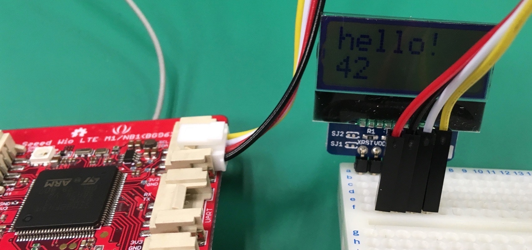
I2C接続小型LCDモジュール 8x2行(AQM0802A)
Wio LTE Cat M1/NB1の接続ポートはI2Cです。
Groveジャンパを使って、LCDに印字と対応させて配線します。
| LCDの印字 | ケーブル |
|---|---|
| VDD | 赤 |
| GND | 黒 |
| SDA | 白 |
| SDL | 黄 |
# include <WioCellLibforArduino.h>
# include <Wire.h>
# include <FaBoLCDmini_AQM0802A.h> // https://github.com/FaBoPlatform/FaBoLCDmini-AQM0802A-Library
                                  // datasheet: http://akizukidenshi.com/download/ds/xiamen/AQM0802.pdf

FaBoLCDmini_AQM0802A  *lcd;
byte lcd_buffer[sizeof(FaBoLCDmini_AQM0802A)];
byte contrast = 24;  // コントラスト(0~63)

WioCellular Wio;

void setup() {
  Wio.Init();
  Wio.PowerSupplyGrove(true);
  delay(500);

  lcd = new(lcd_buffer) FaBoLCDmini_AQM0802A();
  lcd->begin();
  lcd->setContrast(contrast);
  delay(2);

  lcd->print("hello!");
}

void loop() {
  lcd->setCursor(0, 1); // 0列, 1行目にカーソルを移動

  char buf[64];
  sprintf(buf, "%ld", (millis() / 1000)); // 起動してからの経過秒数の文字を生成
  lcd->print(buf);

  delay(100);
}