はじめに
Docker上のFRRoutingでOSPFを動かしてみるに引き続き、個人のノートPCでお手軽に、なるべく省リソースでネットワークの勉強/検証をしたい、という動機から、Docker+FRRoutingを試してみています。今回はMPLS-VPNをやっていきます。
※誤り等ありましたらお気軽にコメントいただければと思います。
2021/1/13追記:docker-compose版も作りました。
参考にしたページ
MPLSについてはこちらのページにお世話になっているので、検証構成とコンフィグ設計はこちらをベースにしました。
また、FRRoutingを使ったMPLSの環境構築については、こちらを参考にさせていただきました。
- FRRoutingでMPLS L3-VPNのようなもの
- [Use Linux as an MPLS Router]
(https://blog.swineson.me/en/use-linux-as-an-mpls-router/)
検証環境
- Windows 10 (Core i7, 12GB RAM)
- VirtualBox 6.1
- Ubuntu 18.04 (2 Core, 4GB RAM, 10GB Disk)
- Docker 20.10.2
- FRRouting 7.5
Dockerまではインストールされた状態から始めます。
検証構成
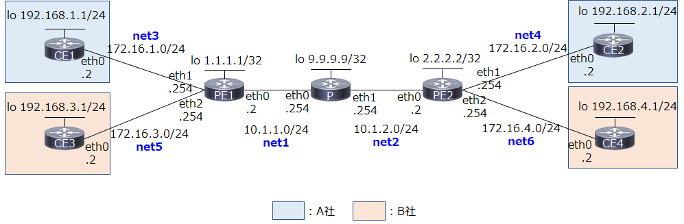
MPLS-VPN 検証構成とコンフィグ設定(PE-CE間でスタティックルートを使用)に則った構成とアドレス設計です。違うのは、各ネットワークで.1ではなく.2を使っていること(Docker networkのbridge用アドレスを.1とするため)、PE1/PE2でコア側をeth0、ユーザ側を順にeth1, 2としている所です。
青字はdocker network(bridge)での実装におけるネットワーク名です。Dockerでは、複数のネットワークをコンテナにアタッチする際、GWやInternal等の属性が同じ場合は、ネットワーク名の辞書順にコンテナ内のeth0, 1, 2, ...に割り当てられるようです1 2。今回、PEルータではコア側をeth0、ユーザ側を順にeth1, 2, ...と統一したかったので、上記のような命名規則で対応することにしました。
全体の流れ
手順全体の流れと、設定対象機器は以下の通りです。
| 順番 | 内容 | Pルータ | PEルータ | CEルータ |
|---|---|---|---|---|
| 1 | ホストOSの設定 | - | - | - |
| 2 | Dockerネットワークとコンテナ作成 | ○ | ○ | ○ |
| 3 | FRR daemonの設定 | ○ | ○ | - |
| 4 | OSPFの設定 | ○ | ○ | - |
| 5 | LDPの設定 | ○ | ○ | - |
| 6 | MP-BGPの設定 | - | ○ | - |
| 7 | VRFの設定 | - | ○ | - |
| 8 | CEルータの設定 | - | - | ○ |
1. ホストOSの設定
はじめに、ホストOS(Ubuntu VM)の設定をします。
公式docsに従って、MPLSのカーネルモジュールをロードします。
/etc/modules-load.d/modules.confを編集し、mpls_router、mpls_iptunnelを追加。
# /etc/modules: kernel modules to load at boot time.
#
# This file contains the names of kernel modules that should be loaded
# at boot time, one per line. Lines beginning with "#" are ignored.
mpls_router
mpls_iptunnel
# modprobe mpls-router mopls-iptunnel
modprobe: FATAL: Module mpls-router not found in directory /lib/modules/4.15.0-124-generic
エラーになったので、公式の記載に従って拡張パッケージをインストールします。
# apt install linux-modules-extra-`uname -r`
※公式ではapt-get install linux-modules-extra-`uname -r`-genericとなっていましたが最後の-genericはいらないですね。
これで改めてカーネルモジュールをロードします。
# modprobe mpls-router mpls-iptunnel
# lsmod | grep mpls
mpls_router            28672  0
ip_tunnel              24576  1 mpls_router
無事ロードされました。
試しにコンテナを作って、コンテナ内でlsmodをすると、上記2つが反映されています。
# docker run -dit --name test alpine
# docker exec -it test lsmod | grep mpls
mpls_router            28672  0
ip_tunnel              24576  1 mpls_router
MPLS転送を有効にするためのカーネルパラメータの変更は、コンテナ内でやればいいようなので、後でやることにします。
2. Dockerネットワークとコンテナ作成
Docker Network(bridge)を使って独自ネットワークを作り、そこにコンテナをつないでいきます。
ただし、ここで1つ問題があります。Docker Networkを使ったネットワーク作成はお手軽なのですが、コンテナをつないだ際、IPアドレスが自動で設定されます。(もしくは--ipオプションで手動指定)。こうして自動もしくは手動でコンテナkernelによって設定されたIPアドレスは、FRRoutingを使って変更・削除することはできません。また、デフォルトルートを含む複数のルートも自動で設定されてしまい、FRRoutingからは変更・削除できません(かつ、Kernel Routeは最優先)。IPアドレスであればコンテナ作成の際に手動設定してしまい、FRRoutingからは触らないようにする、というのも可能ですが、最大限vtyshを使って設定したいですし、ルートの方はネットワーク設定に支障がある場合もありますので、ip addr delやip route delコマンドで削除する必要があります。
※こうした自動設定を止める設定があるかもしれませんが見つけられていません...
地道に1つずつ手動で消していってもいいのですが、今回コンテナが7つもあるので、そういった初期設定済みのFRRイメージを作成するDockerfileを作りました。これを使って作った独自のFRRイメージを使って環境構築していきたいと思います。ついでにtcpdumpもインストールしています。
(tcpdumpに関してはホストOS側でvethを特定して...でもいいですが)
初期設定済みのFRRoutingイメージを作る
適当なフォルダにDockerfileを作ります。
FROM frrouting/frr:v7.5.0
RUN apk update && apk add tcpdump
COPY docker-start /usr/lib/frr/docker-start
もともとのFRRoutingのイメージに、tcpdumpをインストールし、かつヘルパースクリプトを独自のものに置き換えています。
同じディレクトリにdocker-startという名前でヘルパースクリプトを作成。
# !/bin/sh

set -e

# Delete all IP addresses on ethX
devlist=`ip -o addr | cut -d\  -f 2 | sed '1d'`
for dev in $devlist
do
  IP=`ip -o addr show $dev | cut -d\  -f 7`
  ip addr del $IP dev $dev
done

# Delete all routes
routelist=`ip route | cut -d\  -f 1`
for route in $routelist
do
  ip route del $route
done


##
# For volume mounts...
##
chown -R frr:frr /etc/frr || true
/usr/lib/frr/frrinit.sh start

# Sleep forever
exec tail -f /dev/null
これは、もともとFRRoutingで使われているスクリプトに、IPアドレスとルート全削除の処理を加えたものです。
スクリプトに実行権限を与えて、docker build
# chmod +x docker-start
# docker build -t frr .
# docker images
REPOSITORY          TAG                 IMAGE ID            CREATED             SIZE
frr                 latest              42eb8fb2ebb3        4 seconds ago       128MB
以降、コンテナ作成の際はfrrouting/frr:v7.5.0ではなく、frrを使っていきます。
ネットワークの作成
まずnetworkを作ります。
# docker network create net1 --subnet=10.1.1.0/24
# docker network create net2 --subnet=10.1.2.0/24
# docker network create net3 --subnet=172.16.1.0/24
# docker network create net4 --subnet=172.16.2.0/24
# docker network create net5 --subnet=172.16.3.0/24
# docker network create net6 --subnet=172.16.4.0/24
# docker network ls
NETWORK ID     NAME      DRIVER    SCOPE
4f627b43f43a   bridge    bridge    local
62dced673495   host      host      local
b6c924d827f5   net1      bridge    local
ac750081ae13   net2      bridge    local
f96230418508   net3      bridge    local
9553456d0ad7   net4      bridge    local
5c39ee2ea4d7   net5      bridge    local
f2e362f4eaad   net6      bridge    local
20f96b0038a3   none      null      local
Pルータの作成
名前が1文字のコンテナは作れないようだったので、コンテナ名、ホスト名はPRとしました。
# docker create -it --name PR --hostname PR --privileged --net net1 frr
# docker network connect net2 PR
# docker start PR
いきなりdocker runするのではなく、docker create docker network connectでネットワークを全部つないでからコンテナを起動します。
PEルータの作成
# docker create -it --name PE1 --hostname PE1 --privileged --net net1 frr
# docker network connect net3 PE1
# docker network connect net5 PE1
# docker start PE1

# docker create -it --name PE2 --hostname PE2 --privileged --net net2 frr
# docker network connect net4 PE2
# docker network connect net6 PE2
# docker start PE2
CEルータの作成
# docker run -dit --name CE1 --hostname CE1 --privileged --net net3 frr
# docker run -dit --name CE2 --hostname CE2 --privileged --net net4 frr
# docker run -dit --name CE3 --hostname CE3 --privileged --net net5 frr
# docker run -dit --name CE4 --hostname CE4 --privileged --net net6 frr
動作確認
# docker ps
CONTAINER ID   IMAGE     COMMAND                  CREATED          STATUS          PORTS     NAMES
01c534d3bafa   frr       "/sbin/tini -- /usr/…"   5 seconds ago    Up 3 seconds              CE4
861ce203d498   frr       "/sbin/tini -- /usr/…"   20 seconds ago   Up 19 seconds             CE3
acd7834f981b   frr       "/sbin/tini -- /usr/…"   32 seconds ago   Up 31 seconds             CE2
5ce59162b01b   frr       "/sbin/tini -- /usr/…"   56 seconds ago   Up 54 seconds             CE1
99bb821a4cb8   frr       "/sbin/tini -- /usr/…"   4 minutes ago    Up 3 minutes              PE2
824e0a5a5337   frr       "/sbin/tini -- /usr/…"   5 minutes ago    Up 5 minutes              PE1
aeaab8e9b887   frr       "/sbin/tini -- /usr/…"   6 minutes ago    Up 6 minutes              PR
コンテナが7つ起動していることを確認します。
3. FRR Daemonの設定
FRRの設定ファイルで、起動するdaemonを指定します。/etc/frr/daemonsを編集し、起動するdaemonをyesにしていきます。
各ルータにおいて(追加で)起動するdaemonは以下の通り。
| ルータ種別 | 起動するdaemon |
|---|---|
| Pルータ | ospfd, ldpd |
| PEルータ | bgpd, ospfd, ldpd |
| CEルータ | - |
今回、CEルータとPEルータの間はStaticルーティングを使うため、CEルータでは特に追加でdaemonを起動する必要はありません。
Pルータ
(略)
ospfd=yes
(略)
ldpd=yes
(略)
PEルータ
(略)
bgpd=yes
(略)
ospfd=yes
(略)
ldpd=yes
(略)
それぞれ、設定ファイルの編集が終わったら設定反映のため、FRRのプロセスを再起動します。
Pルータの例:
/ # /usr/lib/frr/frrinit.sh restart
Stopped watchfrr
Cannot stop ldpd: pid file not found
Cannot stop ospfd: pid file not found
Stopped staticdStopped zebra

Started watchfrr
Cannot stop ldpdとCannot stop ospfdが出ていますが、初回なので問題ありません。
動作確認
各コンテナ内で、指定したプロセスが立ち上がっているか確認します。
Pルータの例:
/ # ps
PID   USER     TIME  COMMAND
    1 root      0:00 /sbin/tini -- /usr/lib/frr/docker-start
    7 root      0:00 tail -f /dev/null
   56 root      0:00 /bin/sh
   88 root      0:00 /usr/lib/frr/watchfrr -d -F traditional zebra ospfd ldpd staticd
  106 frr       0:00 /usr/lib/frr/zebra -d -F traditional -A 127.0.0.1 -s 90000000
  111 frr       0:00 /usr/lib/frr/ospfd -d -F traditional -A 127.0.0.1
  114 frr       0:00 /usr/lib/frr/ldpd -L -u frr -g frr
  115 frr       0:00 /usr/lib/frr/ldpd -E -u frr -g frr
  116 frr       0:00 /usr/lib/frr/ldpd -d -F traditional -A 127.0.0.1
  120 frr       0:00 /usr/lib/frr/staticd -d -F traditional -A 127.0.0.1
  122 root      0:00 ps
ospfdとldpdが立ち上がっています。
4. OSPFの設定
まずはMPLSコア網の土台となるアンダーレイネットワークを作っていきます。今回はIGPとしてOSPFを使用。また、各ルータのループバックIFとして、dummy IFを作るやり方のページもありますが、本記事では各コンテナに最初からあるloを活用していきます。
Pルータ
PR# conf
PR(config)# interface lo
PR(config-if)# ip address 9.9.9.9/32
PR(config-if)# exit

PR(config)# interface eth0
PR(config-if)# ip address 10.1.1.254/24
PR(config-if)# exit

PR(config)# interface eth1
PR(config-if)# ip address 10.1.2.254/24
PR(config-if)# exit

PR(config)# router ospf
PR(config-router)# network 9.9.9.9/32 area 0
PR(config-router)# network 10.1.1.0/24 area 0
PR(config-router)# network 10.1.2.0/24 area 0
PR(config-router)# end
PEルータ
PE1# conf
PE1(config)# interface lo
PE1(config-if)# ip address 1.1.1.1/32
PE1(config-if)# exit

PE1(config)# interface eth0
PE1(config-if)# ip address 10.1.1.2/24
PE1(config-if)# exit

PE1(config)# interface eth1
PE1(config-if)# ip address 172.16.1.254/24
PE1(config-if)# exit

PE1(config)# interface eth2
PE1(config-if)# ip address 172.16.3.254/24
PE1(config-if)# exit

PE1(config)# router ospf
PE1(config-router)# network 1.1.1.1/32 area 0
PE1(config-router)# network 10.1.1.0/24 area 0
PE1(config-router)# end
PE1# conf
PE1(config)# interface lo
PE1(config-if)# ip address 2.2.2.2/32
PE1(config-if)# exit

PE1(config)# interface eth0
PE1(config-if)# ip address 10.1.2.2/24
PE1(config-if)# exit

PE1(config)# interface eth1
PE1(config-if)# ip address 172.16.2.254/24
PE1(config-if)# exit

PE1(config)# interface eth2
PE1(config-if)# ip address 172.16.4.254/24
PE1(config-if)# exit

PE1(config)# router ospf
PE1(config-router)# network 2.2.2.2/32 area 0
PE1(config-router)# network 10.1.2.0/24 area 0
PE1(config-router)# end
動作確認
Pルータで確認してみます。
PR# show ip ospf neighbor

Neighbor ID     Pri State           Dead Time Address         Interface                        RXmtL RqstL DBsmL
1.1.1.1           1 Full/Backup       36.732s 10.1.1.2        eth0:10.1.1.254                      0     0     0
2.2.2.2           1 Full/Backup       34.071s 10.1.2.2        eth1:10.1.2.254                      0     0     0
1.1.1.1, 2.2.2.2とneighborが確立できていることを確認。
PR# show ip route
Codes: K - kernel route, C - connected, S - static, R - RIP,
       O - OSPF, I - IS-IS, B - BGP, E - EIGRP, N - NHRP,
       T - Table, v - VNC, V - VNC-Direct, A - Babel, D - SHARP,
       F - PBR, f - OpenFabric,
       > - selected route, * - FIB route, q - queued, r - rejected, b - backup

O>* 1.1.1.1/32 [110/10] via 10.1.1.2, eth0, weight 1, 00:04:48
O>* 2.2.2.2/32 [110/10] via 10.1.2.2, eth1, weight 1, 00:01:19
O   9.9.9.9/32 [110/0] is directly connected, lo, weight 1, 00:09:18
C>* 9.9.9.9/32 is directly connected, lo, 00:12:31
O   10.1.1.0/24 [110/10] is directly connected, eth0, weight 1, 00:09:08
C>* 10.1.1.0/24 is directly connected, eth0, 00:12:00
O   10.1.2.0/24 [110/10] is directly connected, eth1, weight 1, 00:08:45
C>* 10.1.2.0/24 is directly connected, eth1, 00:11:39
1.1.1.1/32, 2.2.2.2/32へのルートがOSPFによって学習できており、FIBに載っていること(*がついていること)を確認します。
念のためpingも。vtyshから抜けて確認。
/ # ping -I 9.9.9.9 1.1.1.1
PING 1.1.1.1 (1.1.1.1) from 9.9.9.9: 56 data bytes
64 bytes from 1.1.1.1: seq=0 ttl=64 time=0.093 ms
64 bytes from 1.1.1.1: seq=1 ttl=64 time=0.488 ms
64 bytes from 1.1.1.1: seq=2 ttl=64 time=0.220 ms
^C
--- 1.1.1.1 ping statistics ---
3 packets transmitted, 3 packets received, 0% packet loss
round-trip min/avg/max = 0.093/0.267/0.488 ms

/ # ping -I 9.9.9.9 2.2.2.2
PING 2.2.2.2 (2.2.2.2) from 9.9.9.9: 56 data bytes
64 bytes from 2.2.2.2: seq=0 ttl=64 time=0.140 ms
64 bytes from 2.2.2.2: seq=1 ttl=64 time=0.340 ms
64 bytes from 2.2.2.2: seq=2 ttl=64 time=0.486 ms
^C
--- 2.2.2.2 ping statistics ---
3 packets transmitted, 3 packets received, 0% packet loss
round-trip min/avg/max = 0.140/0.322/0.486 ms
通りました。
ちなみに、この時点でPE1(1.1.1.1)→PE2(2.2.2.2)にpingを打つと、当然ですが普通のIPパケットとして転送されます。PルータでtcpdumpしながらPE1→PE2にpingしてみます。
# ping -I 1.1.1.1 2.2.2.2
PING 2.2.2.2 (2.2.2.2) from 1.1.1.1: 56 data bytes
64 bytes from 2.2.2.2: seq=0 ttl=63 time=0.146 ms
64 bytes from 2.2.2.2: seq=1 ttl=63 time=0.374 ms
64 bytes from 2.2.2.2: seq=2 ttl=63 time=0.373 ms
^C
--- 2.2.2.2 ping statistics ---
3 packets transmitted, 3 packets received, 0% packet loss
round-trip min/avg/max = 0.146/0.297/0.374 ms
/ # tcpdump -n -i any icmp
tcpdump: data link type LINUX_SLL2
tcpdump: verbose output suppressed, use -v[v]... for full protocol decode
listening on any, link-type LINUX_SLL2 (Linux cooked v2), snapshot length 262144 bytes
06:51:43.879037 eth0  In  IP 1.1.1.1 > 2.2.2.2: ICMP echo request, id 44032, seq 0, length 64
06:51:43.879052 eth1  Out IP 1.1.1.1 > 2.2.2.2: ICMP echo request, id 44032, seq 0, length 64
06:51:43.879080 eth1  In  IP 2.2.2.2 > 1.1.1.1: ICMP echo reply, id 44032, seq 0, length 64
06:51:43.879084 eth0  Out IP 2.2.2.2 > 1.1.1.1: ICMP echo reply, id 44032, seq 0, length 64
5. LDPの設定
MPLSの設定に入っていきます。公式docsに記載の通り、事前準備としてカーネルパラメータを変更してMPLS転送を有効にする必要があります。各ルータでカーネルパラメータ設定→LDP設定の順で進めます。
Pルータ
MPLSの有効化
カーネルパラメータを変更してMPLSを有効にします。
まずは状態確認。
/ # sysctl -a | grep mpls
sysctl: error reading key 'net.ipv6.conf.all.stable_secret': I/O error
sysctl: error reading key 'net.ipv6.conf.default.stable_secret': I/O error
sysctl: error reading key 'net.ipv6.conf.eth0.stable_secret': I/O error
sysctl: error reading key 'net.ipv6.conf.eth1.stable_secret': I/O error
sysctl: error reading key 'net.ipv6.conf.lo.stable_secret': I/O error
net.mpls.conf.eth0.input = 0
net.mpls.conf.eth1.input = 0
net.mpls.conf.lo.input = 0
net.mpls.default_ttl = 255
net.mpls.ip_ttl_propagate = 1
net.mpls.platform_labels = 0
ipv6関連のエラーが出ていますが、一旦気にしないで進めます。
Pルータではeth0, eth1の両方でMPLS転送を有効にします。net.mpls.conf.eth0.inputとnet.mpls.conf.eth1.inputを1に、net.mpls.platform_labelsを100000に設定するため、下記のファイルに追記。
# content of this file will override /etc/sysctl.d/*
net.mpls.conf.eth0.input = 1
net.mpls.conf.eth1.input = 1
net.mpls.platform_labels = 100000
設定を反映します。
/ # sysctl -p
net.mpls.conf.eth0.input = 1
net.mpls.conf.eth1.input = 1
net.mpls.platform_labels = 100000
# sysctl -a | grep mpls
sysctl: error reading key 'net.ipv6.conf.all.stable_secret': I/O error
sysctl: error reading key 'net.ipv6.conf.default.stable_secret': I/O error
sysctl: error reading key 'net.ipv6.conf.eth0.stable_secret': I/O error
sysctl: error reading key 'net.ipv6.conf.eth1.stable_secret': I/O error
sysctl: error reading key 'net.ipv6.conf.lo.stable_secret': I/O error
net.mpls.conf.eth0.input = 1
net.mpls.conf.eth1.input = 1
net.mpls.conf.lo.input = 0
net.mpls.default_ttl = 255
net.mpls.ip_ttl_propagate = 1
net.mpls.platform_labels = 100000
値が反映されました。
LDPの設定
MPLSのラベル交換のため、LDPを動かします。
PR# conf
PR(config)# mpls ldp
PR(config-ldp)# address-family ipv4
PR(config-ldp-af)# discovery transport-address 9.9.9.9
PR(config-ldp-af)# interface eth0
PR(config-ldp-af-if)# exit
PR(config-ldp-af)# interface eth1
PR(config-ldp-af-if)# exit
PR(config-ldp-af)# end
MPLS網に参加するインターフェースだけ登録します。(ループバックは不要)
PEルータ
PE1, PE2も同様にカーネルパラメータの設定とLDPの設定をします。
PE1
# content of this file will override /etc/sysctl.d/*
net.mpls.conf.eth0.input = 1
net.mpls.platform_labels = 100000
PE1# conf
PE1(config)# mpls ldp
PE1(config-ldp)# address-family ipv4
PE1(config-ldp-af)# discovery transport-address 1.1.1.1
PE1(config-ldp-af)# interface eth0
PE1(config-ldp-af-if)# exit
PE1(config-ldp-af)# end
PE2
# content of this file will override /etc/sysctl.d/*
net.mpls.conf.eth0.input = 1
net.mpls.platform_labels = 100000
PE2# conf
PE2(config)# mpls ldp
PE2(config-ldp)# address-family ipv4
PE2(config-ldp-af)# discovery transport-address 2.2.2.2
PE2(config-ldp-af)# interface eth0
PE2(config-ldp-af-if)# exit
PE2(config-ldp-af)# end
動作確認
Pルータで確認します。
PR# show mpls ldp neighbor
AF   ID              State       Remote Address    Uptime
ipv4 1.1.1.1         OPERATIONAL 1.1.1.1         00:04:41
ipv4 2.2.2.2         OPERATIONAL 2.2.2.2         00:00:50
LDPのneighborが確立できています。
PR# show mpls ldp binding
AF   Destination          Nexthop         Local Label Remote Label  In Use
ipv4 1.1.1.1/32           1.1.1.1         16          imp-null         yes
ipv4 1.1.1.1/32           2.2.2.2         16          16                no
ipv4 2.2.2.2/32           1.1.1.1         17          16                no
ipv4 2.2.2.2/32           2.2.2.2         17          imp-null         yes
ipv4 9.9.9.9/32           1.1.1.1         imp-null    17                no
ipv4 9.9.9.9/32           2.2.2.2         imp-null    17                no
ipv4 10.1.1.0/24          1.1.1.1         imp-null    imp-null          no
ipv4 10.1.1.0/24          2.2.2.2         imp-null    18                no
ipv4 10.1.2.0/24          1.1.1.1         imp-null    18                no
ipv4 10.1.2.0/24          2.2.2.2         imp-null    imp-null          no
ipv4 172.16.1.0/24        1.1.1.1         -           imp-null          no
ipv4 172.16.2.0/24        2.2.2.2         -           imp-null          no
ipv4 172.16.3.0/24        1.1.1.1         -           imp-null          no
ipv4 172.16.4.0/24        2.2.2.2         -           imp-null          no
「LIBテーブル」の情報が確認できます。
PR# show mpls table
 Inbound Label  Type  Nexthop   Outbound Label
 -----------------------------------------------
 16             LDP   10.1.2.2  implicit-null
 17             LDP   10.1.1.2  implicit-null
こちらは「LFIBテーブル」ですね。
先ほどと同様、PE1(1.1.1.1)→PE2(2.2.2.2)にpingを打ってみます。
/ # ping -c 1 -I 1.1.1.1 2.2.2.2
PING 2.2.2.2 (2.2.2.2) from 1.1.1.1: 56 data bytes
64 bytes from 2.2.2.2: seq=0 ttl=63 time=0.121 ms

--- 2.2.2.2 ping statistics ---
1 packets transmitted, 1 packets received, 0% packet loss
round-trip min/avg/max = 0.121/0.121/0.121 ms
この時、Pルータでパケットキャプチャをすると、生のIPパケットではなく、MPLSラベルのついたパケットが転送されていることがわかります。
/ # tcpdump -n -i any -l | grep ICMP
tcpdump: data link type LINUX_SLL2
tcpdump: verbose output suppressed, use -v[v]... for full protocol decode
listening on any, link-type LINUX_SLL2 (Linux cooked v2), snapshot length 262144 bytes
07:17:28.103630 eth0  In  MPLS (label 17, exp 0, [S], ttl 64) IP 1.1.1.1 > 2.2.2.2: ICMP echo request, id 51200, seq 0, length 64
07:17:28.103636 eth1  Out IP 1.1.1.1 > 2.2.2.2: ICMP echo request, id 51200, seq 0, length 64
07:17:28.103668 eth1  In  MPLS (label 16, exp 0, [S], ttl 64) IP 2.2.2.2 > 1.1.1.1: ICMP echo reply, id 51200, seq 0, length 64
07:17:28.103669 eth0  Out IP 2.2.2.2 > 1.1.1.1: ICMP echo reply, id 51200, seq 0, length 64
行きはlabel 17が付けられたパケットがPルータのeth0から入り、PルータのLFIBテーブル(Label 17に対してimplicit-null)に従ってラベルが剥がされ、生のIPパケットになってeth1から出ていく様子がわかります。帰りはlabel 16で同様の処理が行われています。
6. MP-BGPの設定
PEルータでMP-BGPの設定をします。
まずPE間でiBGPピアを張る設定と、VPN-IPv4のアドレス情報を運ぶためのAddress Familyの設定です。
PE1# conf
PE1(config)# router bgp 65000
PE1(config-router)# neighbor 2.2.2.2 remote-as 65000
PE1(config-router)# neighbor 2.2.2.2 update-source 1.1.1.1
PE1(config-router)# address-family ipv4 vpn
PE1(config-router-af)# neighbor 2.2.2.2 activate
PE1(config-router-af)# exit-address-family
PE1(config-router)# end
PE2も同様に設定します。
PE2# conf
PE2(config)# router bgp 65000
PE2(config-router)# neighbor 1.1.1.1 remote-as 65000
PE2(config-router)# neighbor 1.1.1.1 update-source 2.2.2.2
PE2(config-router)# address-family ipv4 vpn
PE2(config-router-af)# neighbor 1.1.1.1 activate
PE2(config-router-af)# exit-address-family
PE2(config-router)# end
動作確認
PE1# show ip bgp summary

IPv4 Unicast Summary:
BGP router identifier 1.1.1.1, local AS number 65000 vrf-id 0
BGP table version 0
RIB entries 0, using 0 bytes of memory
Peers 1, using 14 KiB of memory

Neighbor        V         AS   MsgRcvd   MsgSent   TblVer  InQ OutQ  Up/Down State/PfxRcd   PfxSnt
2.2.2.2         4      65000        13        16        0    0    0 00:01:16            0        0

Total number of neighbors 1

IPv4 VPN Summary:
BGP router identifier 1.1.1.1, local AS number 65000 vrf-id 0
BGP table version 0
RIB entries 0, using 0 bytes of memory
Peers 1, using 14 KiB of memory

Neighbor        V         AS   MsgRcvd   MsgSent   TblVer  InQ OutQ  Up/Down State/PfxRcd   PfxSnt
2.2.2.2         4      65000        13        16        0    0    0 00:01:16            0        0

Total number of neighbors 1
Up/Downの欄がneverになっていないことを確認します。
VPN-IPv4のBGPテーブルも見てみます。
PE1# show bgp ipv4 vpn
No BGP prefixes displayed, 0 exist
この時点ではまだルートを学習していないので、エントリーはありません。
7. VRFの設定
PE1/PE2で各ユーザごとのVRFを作り、ユーザルートの設定とルート再配送の設定をします。
VRFの作成
各CEルータを収容するためのVRFを作成します。Linux VRFの機能を使っていきます。VRF作成はFRRoutingでできないので、ipコマンドを使って作ります。また、作ったVRFに、対応するIFを所属させます。A社用のVRF名はCUSTA、B社用はCUSTBとします。
/ # ip link
1: lo: <LOOPBACK,UP,LOWER_UP> mtu 65536 qdisc noqueue state UNKNOWN mode DEFAULT group default qlen 1000
    link/loopback 00:00:00:00:00:00 brd 00:00:00:00:00:00
41: eth2@if42: <BROADCAST,MULTICAST,UP,LOWER_UP> mtu 1500 qdisc noqueue state UP mode DEFAULT group default
    link/ether 02:42:ac:10:03:02 brd ff:ff:ff:ff:ff:ff link-netnsid 0
43: eth0@if44: <BROADCAST,MULTICAST,UP,LOWER_UP> mtu 1500 qdisc noqueue state UP mode DEFAULT group default
    link/ether 02:42:0a:01:01:03 brd ff:ff:ff:ff:ff:ff link-netnsid 0
45: eth1@if46: <BROADCAST,MULTICAST,UP,LOWER_UP> mtu 1500 qdisc noqueue state UP mode DEFAULT group default
    link/ether 02:42:ac:10:01:02 brd ff:ff:ff:ff:ff:ff link-netnsid 0

/ # ip link add CUSTA type vrf table 10
/ # ip link add CUSTB type vrf table 20
/ # ip link set CUSTA up
/ # ip link set CUSTB up
/ # ip link set eth1 master CUSTA
/ # ip link set eth2 master CUSTB

/ # ip link
1: lo: <LOOPBACK,UP,LOWER_UP> mtu 65536 qdisc noqueue state UNKNOWN mode DEFAULT group default qlen 1000
    link/loopback 00:00:00:00:00:00 brd 00:00:00:00:00:00
2: CUSTA: <NOARP,MASTER,UP,LOWER_UP> mtu 65536 qdisc noqueue state UP mode DEFAULT group default qlen 1000
    link/ether 12:1b:1d:12:01:7f brd ff:ff:ff:ff:ff:ff
3: CUSTB: <NOARP,MASTER,UP,LOWER_UP> mtu 65536 qdisc noqueue state UP mode DEFAULT group default qlen 1000
    link/ether de:06:68:aa:a5:ec brd ff:ff:ff:ff:ff:ff
41: eth2@if42: <BROADCAST,MULTICAST,UP,LOWER_UP> mtu 1500 qdisc noqueue master CUSTB state UP mode DEFAULT group default
    link/ether 02:42:ac:10:03:02 brd ff:ff:ff:ff:ff:ff link-netnsid 0
43: eth0@if44: <BROADCAST,MULTICAST,UP,LOWER_UP> mtu 1500 qdisc noqueue state UP mode DEFAULT group default
    link/ether 02:42:0a:01:01:03 brd ff:ff:ff:ff:ff:ff link-netnsid 0
45: eth1@if46: <BROADCAST,MULTICAST,UP,LOWER_UP> mtu 1500 qdisc noqueue master CUSTA state UP mode DEFAULT group default
    link/ether 02:42:ac:10:01:02 brd ff:ff:ff:ff:ff:ff link-netnsid 0
vtyshで確認できます。
PE1# show int br
Interface       Status  VRF             Addresses
---------       ------  ---             ---------
CUSTA           up      CUSTA
eth1            up      CUSTA           172.16.1.254/24

Interface       Status  VRF             Addresses
---------       ------  ---             ---------
CUSTB           up      CUSTB
eth2            up      CUSTB           172.16.3.254/24

Interface       Status  VRF             Addresses
---------       ------  ---             ---------
eth0            up      default         10.1.1.2/24
lo              up      default         1.1.1.1/32
PE2でも同様に作成します。
/ # ip link add CUSTA type vrf table 10
/ # ip link add CUSTB type vrf table 20
/ # ip link set CUSTA up
/ # ip link set CUSTB up
/ # ip link set eth1 master CUSTA
/ # ip link set eth2 master CUSTB

/ # ip link
1: lo: <LOOPBACK,UP,LOWER_UP> mtu 65536 qdisc noqueue state UNKNOWN mode DEFAULT group default qlen 1000
    link/loopback 00:00:00:00:00:00 brd 00:00:00:00:00:00
2: CUSTA: <NOARP,MASTER,UP,LOWER_UP> mtu 65536 qdisc noqueue state UP mode DEFAULT group default qlen 1000
    link/ether b6:48:e9:21:1e:6b brd ff:ff:ff:ff:ff:ff
3: CUSTB: <NOARP,MASTER,UP,LOWER_UP> mtu 65536 qdisc noqueue state UP mode DEFAULT group default qlen 1000
    link/ether 16:8f:42:1f:9b:84 brd ff:ff:ff:ff:ff:ff
47: eth0@if48: <BROADCAST,MULTICAST,UP,LOWER_UP> mtu 1500 qdisc noqueue state UP mode DEFAULT group default
    link/ether 02:42:0a:01:02:03 brd ff:ff:ff:ff:ff:ff link-netnsid 0
49: eth1@if50: <BROADCAST,MULTICAST,UP,LOWER_UP> mtu 1500 qdisc noqueue master CUSTA state UP mode DEFAULT group default
    link/ether 02:42:ac:10:02:02 brd ff:ff:ff:ff:ff:ff link-netnsid 0
51: eth2@if52: <BROADCAST,MULTICAST,UP,LOWER_UP> mtu 1500 qdisc noqueue master CUSTB state UP mode DEFAULT group default
    link/ether 02:42:ac:10:04:02 brd ff:ff:ff:ff:ff:ff link-netnsid 0
PE2# show int br
Interface       Status  VRF             Addresses
---------       ------  ---             ---------
CUSTA           up      CUSTA
eth1            up      CUSTA           172.16.2.254/24

Interface       Status  VRF             Addresses
---------       ------  ---             ---------
CUSTB           up      CUSTB
eth2            up      CUSTB           172.16.4.254/24

Interface       Status  VRF             Addresses
---------       ------  ---             ---------
eth0            up      default         10.1.2.2/24
lo              up      default         2.2.2.2/32
ユーザ向けルートの設定
今回CE-PE間はスタティックルーティングを使います。VRF CUSTA, CUSTBそれぞれで設定。
PE1# conf
PE1(config)# ip route 192.168.1.0/24 172.16.1.2 vrf CUSTA
PE1(config)# ip route 192.168.3.0/24 172.16.3.2 vrf CUSTB
PE1(config)# exit

PE1# show ip route vrf CUSTA
Codes: K - kernel route, C - connected, S - static, R - RIP,
       O - OSPF, I - IS-IS, B - BGP, E - EIGRP, N - NHRP,
       T - Table, v - VNC, V - VNC-Direct, A - Babel, D - SHARP,
       F - PBR, f - OpenFabric,
       > - selected route, * - FIB route, q - queued, r - rejected, b - backup

VRF CUSTA:
C>* 172.16.1.0/24 is directly connected, eth1, 04:55:40
S>* 192.168.1.0/24 [1/0] via 172.16.1.2, eth1, weight 1, 04:12:14

PE1# show ip route vrf CUSTB
Codes: K - kernel route, C - connected, S - static, R - RIP,
       O - OSPF, I - IS-IS, B - BGP, E - EIGRP, N - NHRP,
       T - Table, v - VNC, V - VNC-Direct, A - Babel, D - SHARP,
       F - PBR, f - OpenFabric,
       > - selected route, * - FIB route, q - queued, r - rejected, b - backup

VRF CUSTB:
C>* 172.16.3.0/24 is directly connected, eth2, 04:55:37
S>* 192.168.3.0/24 [1/0] via 172.16.3.2, eth2, weight 1, 04:09:52
PE2も同様に設定。
PE2# conf
PE2(config)# ip route 192.168.2.0/24 172.16.2.2 vrf CUSTA
PE2(config)# ip route 192.168.4.0/24 172.16.4.2 vrf CUSTB
PE2(config)# exit

PE2# show ip route vrf CUSTA
Codes: K - kernel route, C - connected, S - static, R - RIP,
       O - OSPF, I - IS-IS, B - BGP, E - EIGRP, N - NHRP,
       T - Table, v - VNC, V - VNC-Direct, A - Babel, D - SHARP,
       F - PBR, f - OpenFabric,
       > - selected route, * - FIB route, q - queued, r - rejected, b - backup

VRF CUSTA:
C>* 172.16.2.0/24 is directly connected, eth1, 05:00:25
S>* 192.168.2.0/24 [1/0] via 172.16.2.2, eth1, weight 1, 04:17:02

PE2# show ip route vrf CUSTB
Codes: K - kernel route, C - connected, S - static, R - RIP,
       O - OSPF, I - IS-IS, B - BGP, E - EIGRP, N - NHRP,
       T - Table, v - VNC, V - VNC-Direct, A - Babel, D - SHARP,
       F - PBR, f - OpenFabric,
       > - selected route, * - FIB route, q - queued, r - rejected, b - backup

VRF CUSTB:
C>* 172.16.4.0/24 is directly connected, eth2, 05:00:26
S>* 192.168.4.0/24 [1/0] via 172.16.4.2, eth2, weight 1, 04:16:34
ルート再配送の設定
VRFのルートテーブルと「グローバルルーティングテーブル」の間の、ルート再配送の設定。
PE1# conf
PE1(config)# router bgp 65000 vrf CUSTA
PE1(config-router)# address-family ipv4 unicast
PE1(config-router-af)# redistribute static
PE1(config-router-af)# label vpn export auto
PE1(config-router-af)# rd vpn export 1:100
PE1(config-router-af)# rt vpn both 10:100
PE1(config-router-af)# export vpn
PE1(config-router-af)# import vpn
PE1(config-router-af)# exit-address-family
PE1(config-router)# exit

PE1(config)# router bgp 65000 vrf CUSTB
PE1(config-router)# address-family ipv4 unicast
PE1(config-router-af)# redistribute static
PE1(config-router-af)# label vpn export auto
PE1(config-router-af)# rd vpn export 2:100
PE1(config-router-af)# rt vpn both 20:100
PE1(config-router-af)# export vpn
PE1(config-router-af)# import vpn
PE1(config-router-af)# exit-address-family
PE1(config-router)# end
この辺り、Ciscoと設定方法が若干違うようですが、やっていることとしては以下のように理解しています。
-
label vpn export auto:VRFからグローバルルーティングテーブルに対してルートをexportする時に、MPLSのラベルを自動でつける -
export|import vpn:VRFとグローバルルーティングテーブル間でルートのimport/exportを可能にする -
VRF内のルート情報(address-family = ipv4 unicast)をグローバルルーティングテーブル側(address-family = VPNv4: RD/RT等の情報が付与されたアドレス情報)に配送する際の設定として、「MPLSのラベル付け」「RD/RT情報の付与」「そもそもVRF内のルート⇔グローバルルーティングテーブルの情報のやりとりをONにする」という設定を行っている。
また、今回CE-PE間はStaticルーティングでの設定としているため、redistribute staticとしています。
PE2も同様に設定。
PE2# conf
PE2(config)# router bgp 65000 vrf CUSTA
PE2(config-router)# address-family ipv4 unicast
PE2(config-router-af)# redistribute static
PE2(config-router-af)# label vpn export auto
PE2(config-router-af)# rd vpn export 1:100
PE2(config-router-af)# rt vpn both 10:100
PE2(config-router-af)# export vpn
PE2(config-router-af)# import vpn
PE2(config-router-af)# exit-address-family
PE2(config-router)# exit

PE2(config)# router bgp 65000 vrf CUSTB
PE2(config-router)# address-family ipv4 unicast
PE2(config-router-af)# redistribute static
PE2(config-router-af)# label vpn export auto
PE2(config-router-af)# rd vpn export 2:100
PE2(config-router-af)# rt vpn both 20:100
PE2(config-router-af)# export vpn
PE2(config-router-af)# import vpn
PE2(config-router-af)# exit-address-family
PE2(config-router)# end
これを設定すると、BGPでユーザルートが学習されます。
動作確認
PE1で確認。まずはBGPテーブル(VPN-IPv4ルート)を見てみます。
PE1# show ip bgp ipv4 vpn
BGP table version is 6, local router ID is 1.1.1.1, vrf id 0
Default local pref 100, local AS 65000
Status codes:  s suppressed, d damped, h history, * valid, > best, = multipath,
               i internal, r RIB-failure, S Stale, R Removed
Nexthop codes: @NNN nexthop's vrf id, < announce-nh-self
Origin codes:  i - IGP, e - EGP, ? - incomplete

   Network          Next Hop            Metric LocPrf Weight Path
Route Distinguisher: 1:100
*> 192.168.1.0/24   172.16.1.2@2<            0         32768 ?
    UN=172.16.1.2 EC{10:100} label=146 type=bgp, subtype=5
*>i192.168.2.0/24   2.2.2.2                  0    100      0 ?
    UN=2.2.2.2 EC{10:100} label=146 type=bgp, subtype=0
Route Distinguisher: 2:100
*> 192.168.3.0/24   172.16.3.2@3<            0         32768 ?
    UN=172.16.3.2 EC{20:100} label=147 type=bgp, subtype=5
*>i192.168.4.0/24   2.2.2.2                  0    100      0 ?
    UN=2.2.2.2 EC{20:100} label=147 type=bgp, subtype=0

Displayed  4 routes and 4 total paths
ユーザルートが載りました。PE2で設定した192.168.2.0/24と192.168.4.0/24もiBGPで学習されています。先ほど設定したRD/RT情報も載っています。
次に、VRFごとのBGPテーブル。
PE1# show ip bgp vrf CUSTA
BGP table version is 2, local router ID is 172.16.1.254, vrf id 2
Default local pref 100, local AS 65000
Status codes:  s suppressed, d damped, h history, * valid, > best, = multipath,
               i internal, r RIB-failure, S Stale, R Removed
Nexthop codes: @NNN nexthop's vrf id, < announce-nh-self
Origin codes:  i - IGP, e - EGP, ? - incomplete

   Network          Next Hop            Metric LocPrf Weight Path
*> 192.168.1.0/24   172.16.1.2               0         32768 ?
*> 192.168.2.0/24   2.2.2.2@0<               0    100      0 ?

Displayed  2 routes and 2 total paths
PE1# show ip bgp vrf CUSTB
BGP table version is 4, local router ID is 172.16.3.254, vrf id 3
Default local pref 100, local AS 65000
Status codes:  s suppressed, d damped, h history, * valid, > best, = multipath,
               i internal, r RIB-failure, S Stale, R Removed
Nexthop codes: @NNN nexthop's vrf id, < announce-nh-self
Origin codes:  i - IGP, e - EGP, ? - incomplete

   Network          Next Hop            Metric LocPrf Weight Path
*> 192.168.3.0/24   172.16.3.2               0         32768 ?
*> 192.168.4.0/24   2.2.2.2@0<               0    100      0 ?

Displayed  2 routes and 2 total paths
それぞれユーザルートが正しく学習されています。
次に、VRFごとのルートテーブルを見てみます。
PE1# show ip route vrf CUSTA
Codes: K - kernel route, C - connected, S - static, R - RIP,
       O - OSPF, I - IS-IS, B - BGP, E - EIGRP, N - NHRP,
       T - Table, v - VNC, V - VNC-Direct, A - Babel, D - SHARP,
       F - PBR, f - OpenFabric,
       > - selected route, * - FIB route, q - queued, r - rejected, b - backup

VRF CUSTA:
C>* 172.16.1.0/24 is directly connected, eth1, 05:29:08
S>* 192.168.1.0/24 [1/0] via 172.16.1.2, eth1, weight 1, 04:45:42
B>  192.168.2.0/24 [200/0] via 2.2.2.2 (vrf default) (recursive), label 146, weight 1, 00:04:28
  *                          via 10.1.1.254, eth0 (vrf default), label 17/146, weight 1, 00:04:28
PE1# show ip route vrf CUSTB
Codes: K - kernel route, C - connected, S - static, R - RIP,
       O - OSPF, I - IS-IS, B - BGP, E - EIGRP, N - NHRP,
       T - Table, v - VNC, V - VNC-Direct, A - Babel, D - SHARP,
       F - PBR, f - OpenFabric,
       > - selected route, * - FIB route, q - queued, r - rejected, b - backup

VRF CUSTB:
C>* 172.16.3.0/24 is directly connected, eth2, 05:29:07
S>* 192.168.3.0/24 [1/0] via 172.16.3.2, eth2, weight 1, 04:43:22
B>  192.168.4.0/24 [200/0] via 2.2.2.2 (vrf default) (recursive), label 147, weight 1, 00:16:20
  *                          via 10.1.1.254, eth0 (vrf default), label 17/147, weight 1, 00:16:20
それぞれ、BGPテーブルを介して、PE2から受信したユーザルートが載っていることがわかります。
8. CEルータの設定
最後に、CEの設定をしていきます。
ループバックアドレス、PE向かいのアドレス、デフォルトルートを設定します。
CE1# conf
CE1(config)# interface lo
CE1(config-if)# ip address 192.168.1.1/24
CE1(config-if)# exit
CE1(config)# interface eth0
CE1(config-if)# ip address 172.16.1.2/24
CE1(config-if)# exit
CE1(config)# ip route 0.0.0.0/0 172.16.1.254
CE1(config)# end
CE2~4も同様。
CE2# conf
CE2(config)# interface lo
CE2(config-if)# ip address 192.168.2.1/24
CE2(config-if)# exit
CE2(config)# interface eth0
CE2(config-if)# ip address 172.16.2.2/24
CE2(config-if)# exit
CE2(config)# ip route 0.0.0.0/0 172.16.2.254
CE2(config)# end
CE3# conf
CE3(config)# interface lo
CE3(config-if)# ip address 192.168.3.1/24
CE3(config-if)# exit
CE3(config)# interface eth0
CE3(config-if)# ip address 172.16.3.2/24
CE3(config-if)# exit
CE3(config)# ip route 0.0.0.0/0 172.16.3.254
CE3(config)# end
CE4# conf
CE4(config)# interface lo
CE4(config-if)# ip address 192.168.4.1/24
CE4(config-if)# exit
CE4(config)# interface eth0
CE4(config-if)# ip address 172.16.4.2/24
CE4(config-if)# exit
CE4(config)# ip route 0.0.0.0/0 172.16.4.254
CE4(config)# end
動作確認
これですべて完成したはずです。
CE1→CE2にpingが通ることを確認します。-IでSourceとしてループバックIFを指定。
/ # ping -I 192.168.1.1 192.168.2.1
PING 192.168.2.1 (192.168.2.1) from 192.168.1.1: 56 data bytes
64 bytes from 192.168.2.1: seq=0 ttl=62 time=0.650 ms
64 bytes from 192.168.2.1: seq=1 ttl=62 time=0.751 ms
64 bytes from 192.168.2.1: seq=2 ttl=62 time=0.675 ms
^C
--- 192.168.2.1 ping statistics ---
3 packets transmitted, 3 packets received, 0% packet loss
round-trip min/avg/max = 0.650/0.692/0.751 ms
通りました!
CE3→CE4にpingが通ることを確認します。
/ # ping -I 192.168.3.1 192.168.4.1
PING 192.168.4.1 (192.168.4.1) from 192.168.3.1: 56 data bytes
64 bytes from 192.168.4.1: seq=0 ttl=62 time=0.470 ms
64 bytes from 192.168.4.1: seq=1 ttl=62 time=0.157 ms
64 bytes from 192.168.4.1: seq=2 ttl=62 time=0.777 ms
^C
--- 192.168.4.1 ping statistics ---
3 packets transmitted, 3 packets received, 0% packet loss
round-trip min/avg/max = 0.157/0.468/0.777 ms
通りました!
試しに、CE1→CE4には通らないことを確認します。
/ # ping -I 192.168.1.1 192.168.4.1
PING 192.168.4.1 (192.168.4.1) from 192.168.1.1: 56 data bytes
^C
--- 192.168.4.1 ping statistics ---
3 packets transmitted, 0 packets received, 100% packet loss
通らないので成功です!
パケットキャプチャしてみる
上記CE1→CE2のpingの際、PE1のeth1,0, Pルータのeth0,1, PE2のeth0,1でパケットキャプチャすると、ラベルがついたり取られたりしながらパケットが転送される様子が見えます。
/ # tcpdump -n -i any -l | grep ICMP
/ # ping -c 1 -I 192.168.1.1 192.168.2.1
PING 192.168.2.1 (192.168.2.1) from 192.168.1.1: 56 data bytes
64 bytes from 192.168.2.1: seq=0 ttl=62 time=0.551 ms

--- 192.168.2.1 ping statistics ---
1 packets transmitted, 1 packets received, 0% packet loss
round-trip min/avg/max = 0.551/0.551/0.551 ms
結果を時系列で並べると以下のようになりました。
行き:
08:13:50.550878 eth1  In  IP 192.168.1.1 > 192.168.2.1: ICMP echo request, id 20992, seq 0, length 64
08:13:50.550900 eth0  Out MPLS (label 17, exp 0, ttl 63) (label 146, exp 0, [S], ttl 63) IP 192.168.1.1 > 192.168.2.1: ICMP echo request, id 20992, seq 0, length 64
08:13:50.550905 eth0  In  MPLS (label 17, exp 0, ttl 63) (label 146, exp 0, [S], ttl 63) IP 192.168.1.1 > 192.168.2.1: ICMP echo request, id 20992, seq 0, length 64
08:13:50.550909 eth1  Out MPLS (label 146, exp 0, [S], ttl 63) IP 192.168.1.1 > 192.168.2.1: ICMP echo request, id 20992, seq 0, length 64
08:13:50.550913 eth0  In  MPLS (label 146, exp 0, [S], ttl 63) IP 192.168.1.1 > 192.168.2.1: ICMP echo request, id 20992, seq 0, length 64
08:13:50.550916 CUSTA Out IP 192.168.1.1 > 192.168.2.1: ICMP echo request, id 20992, seq 0, length 64
08:13:50.550926 eth1  Out IP 192.168.1.1 > 192.168.2.1: ICMP echo request, id 20992, seq 0, length 64
PE1のeth0に届くのは生のIPパケットですが、そこで内側のラベル146(VPN識別用)と外側のラベル17(MPLS網内転送用)がつけられeth1から出ていきます。PRではLFIBテーブル(Label 17に対してはimplicit null)にしたがって外側のラベルが剥がされた状態でPE2に転送されています。PE2では内側のラベルも剥がされ、VRF CUSTAのルーティングテーブルに従って生のIPパケットとしてCE2に転送されています。 最後Outが2つあるのはVRF CUSTAとeth1の分ですね。3
帰り:
帰りも同様です。内側のVPN識別用ラベルとしては146が割り当てられています。
08:13:50.550976 eth1  In  IP 192.168.2.1 > 192.168.1.1: ICMP echo reply, id 20992, seq 0, length 64
08:13:50.550981 eth0  Out MPLS (label 16, exp 0, ttl 63) (label 146, exp 0, [S], ttl 63) IP 192.168.2.1 > 192.168.1.1: ICMP echo reply, id 20992, seq 0, length 64
08:13:50.550984 eth1  In  MPLS (label 16, exp 0, ttl 63) (label 146, exp 0, [S], ttl 63) IP 192.168.2.1 > 192.168.1.1: ICMP echo reply, id 20992, seq 0, length 64
08:13:50.550986 eth0  Out MPLS (label 146, exp 0, [S], ttl 63) IP 192.168.2.1 > 192.168.1.1: ICMP echo reply, id 20992, seq 0, length 64
08:13:50.550988 eth0  In  MPLS (label 146, exp 0, [S], ttl 63) IP 192.168.2.1 > 192.168.1.1: ICMP echo reply, id 20992, seq 0, length 64
08:13:50.550990 CUSTA Out IP 192.168.2.1 > 192.168.1.1: ICMP echo reply, id 20992, seq 0, length 64
08:13:50.550994 eth1  Out IP 192.168.2.1 > 192.168.1.1: ICMP echo reply, id 20992, seq 0, length 64
参考
- MPLSをはじめから
- MPLS-VPN 検証構成とコンフィグ設定(PE-CE間でスタティックルートを使用)
- FRRoutingでMPLS L3-VPNのようなもの
- [Use Linux as an MPLS Router]
(https://blog.swineson.me/en/use-linux-as-an-mpls-router/) - Linux VRF with L3 Master Device
-
tcpdumpのIF指定を
-i anyにすると、VRF CUSTAへのINが表示されないようです。個別にIF指定するとどちらも表示されるのですが... なぜだろう... ↩