(2020年03月12日)Rによる投稿
R経由でGnuplotを用いて円を回転させる…一時期そんな事に熱中していました。最初期の成果が以下となります。

# 複素平面(球面)

Complex_plane<-function(x){

# グラフのスケール決定
Graph_scale_x<-c(-1,1)
Graph_scale_y<-c(-1,1)
# 円弧描写の準備
theta <- c(seq(0, pi, length=180),seq(-pi, 0, length=180))
dr<-seq(0,2*pi,length=360)
theta00<- seq(1, -1, length=360)
theta01 <- c(theta[x:360],theta[1:x-1])
theta_sin<-sin(theta01)
# 方向の正負(左右とも緑)
segC<-rgb(0,1,0)
theta02<-dr[1:x]
theta02_cos<-cos(theta02)
theta02_sin<-sin(theta02)
# 円弧の描写

plot(cos(theta), sin(theta), xlim=Graph_scale_x,ylim=Graph_scale_y,type="l",col=rgb(0,0,0), main="Circle area", xlab="X", ylab="Y")

# インジケーター

segments(cos(dr[x]),sin(dr[x]),0,0,col=segC)
polygon(c(theta02_cos,0), #x
c(theta02_sin,0), #y
density=c(30), #塗りつぶす濃度
angle=c(45),     #塗りつぶす斜線の角度
col=segC)  #塗りつぶす色

 }
# アニメーションさせてみる。

library("animation")
# Time_Code=c(1,90,180,270)
Time_Code=c(1,15,30,45,60,75,90,105,120,135,150,165,180,195,210,225,240,255,270,285,300,315,330,345)
saveGIF({
for (i in Time_Code){
  Complex_plane(i)
}
}, interval = 0.1, movie.name = "TEST01.gif")

# 複素平面(球面)

Complex_plane<-function(x){
# グラフのスケール決定
Graph_scale_x<-c(-1,1)
Graph_scale_y<-c(-1,1)
# 円弧描写の準備
theta <- c(seq(0, pi, length=180),seq(-pi, 0, length=180))
theta00<- seq(1, -1, length=360)
theta01 <- c(theta[x:360],theta[1:x-1])
theta_sin<-sin(theta01)
# 方向の正負(右が緑、左が赤)
htc=seq(1:360)
cos2<-function(x){cos(2*x/360*2*pi)/2+0.5}
htcval=cos2(htc)
Rotation_ratio<-htcval[c(x)]
htcval_sin=sin(theta)
htcval_cos=cos(theta)*Rotation_ratio
ifelse((x%/%90==0 || x%/%90==3),C_Top<-rgb(1,0,0),C_Top<-rgb(0,1,0))
ifelse((x%/%90==0 || x%/%90==3),C_Bottom<-rgb(0,1,0),C_Bottom<-rgb(1,0,0))
f0<-function(x){sqrt(1-x^2)*Rotation_ratio}
f1<-function(x){-sqrt(1-x^2)*Rotation_ratio}
# 円弧の描写(ベース)
plot(cos(theta), sin(theta), xlim=Graph_scale_x,ylim=Graph_scale_y,type="l",col=rgb(0,0,0), main="Sphere area", xlab="X", ylab="Y")
par(new=T)#上書き指定
# 円弧の描写(回転)
plot(f0,xlim=Graph_scale_x,ylim=Graph_scale_y,type="l",col=C_Top,main="", xlab="", ylab="")
par(new=T)#上書き指定
plot(f1,xlim=Graph_scale_x,ylim=Graph_scale_y,type="l",col=C_Bottom,main="", xlab="", ylab="")
# 円の塗り潰し
polygon(htcval_sin, #x
htcval_cos, #y
density=c(50*(1-Rotation_ratio)), #塗りつぶす濃度
angle=c(45),     #塗りつぶす斜線の角度
col=C_Top)  #塗りつぶす色
}
# アニメーションさせてみる。

library("animation")
Time_Code=c(1,15,30,45,60,75,90,105,120,135,150,165,180,195,210,225,240,255,270,285,300,315,330,345)
saveGIF({
for (i in Time_Code){
Complex_plane(i)
}
}, interval = 0.1, movie.name = "TEST02.gif")

# 複素平面(球面)

Complex_plane<-function(x){

# グラフのスケール決定
Graph_scale_x<-c(-1,1)
Graph_scale_y<-c(-1,1)
# 円弧描写の準備
theta <- c(seq(0, pi, length=180),seq(-pi, 0, length=180))
dr<-seq(0,2*pi,length=360)
theta00<- seq(1, -1, length=360)
theta01 <- c(theta[x:360],theta[1:x-1])
theta_sin<-sin(theta01)
# 方向の正負(右が緑、左が赤)

htc=seq(1:360)
cos2<-function(x){cos(2*x/360*2*pi)/2+0.5}
htcval=cos2(htc)
Rotation_ratio<-htcval[c(x)]
ifelse((x%/%90==0 || x%/%90==3),segC<-rgb(1,0,0),segC<-rgb(0,1,0))
theta02<-dr[1:x]
ifelse((x%/%90==0 || x%/%90==3),C_Top<-rgb(1,0,0),C_Top<-rgb(0,1,0))
ifelse((x%/%90==0 || x%/%90==3),C_Bottom<-rgb(0,1,0),C_Bottom<-rgb(1,0,0))
f0<-function(x){sqrt(1-x^2)*Rotation_ratio}
f1<-function(x){-sqrt(1-x^2)*Rotation_ratio}

theta02_cos<-cos(theta02)
ifelse((x%/%90==0 || x%/%90==3),theta02_sin<-sin(theta02)*Rotation_ratio,theta02_sin<-sin(theta02)*-Rotation_ratio)
# 円弧の描写

plot(cos(theta), sin(theta), xlim=Graph_scale_x,ylim=Graph_scale_y,type="l",col=rgb(0,0,0), main="Sphere area", xlab="Real Expanse", ylab="Y")
par(new=T)#上書き指定

plot(f0, xlim=Graph_scale_x,ylim=Graph_scale_y,type="l",col=C_Top,main="", xlab="", ylab="")
par(new=T)#上書き指定
plot(f1, xlim=Graph_scale_x,ylim=Graph_scale_y,type="l",col=C_Bottom,main="", xlab="", ylab="")

# インジケーター

# segments(cos(dr[x]),sin(dr[x])*Rotation_ratio,0,0,col=segC)
polygon(c(0,theta02_cos), #x
c(0,theta02_sin), #y
density=c(50*(1-Rotation_ratio)), #塗りつぶす濃度
angle=c(45),     #塗りつぶす斜線の角度
col=segC)  #塗りつぶす色

 }
# アニメーションさせてみる。

library("animation")
Time_Code=c(1,15,30,45,60,75,90,105,120,135,150,165,180,195,210,225,240,255,270,285,300,315,330,345)
saveGIF({
for (i in Time_Code){
  Complex_plane(i)
}
}, interval = 0.1, movie.name = "TEST.gif")
細部は目も当てられない有様ですが、それでもそれなりにプログラミングの過程で学んだ事が多かったものです。それについて触れるのはまた別の機会に。そして、やがて「緯度と経度」すなわち半径と二つの複素数で座標を表示しZ軸の回転で向きを調整する方法に辿り着きます。
「ジンバルロック問題」との邂逅(?)
とりあえず、この頃までに以下のルールが定まっていました。
旅客機についているナビゲーションライトの重要な役割とは
- これまで積み上げてきた右手法に基づく座標体系では「X軸=前後」「Y軸=上下」となるので自然な拡張の結果として「Z軸=左右」となる。
- 画面上では重ねて表示する事しか出来ないので、航空機のナビゲーション・ライトの規定に従って「右=緑」「左=赤」なる表示方法を採用する。
まずは「緯度と経度とその場回転」法の基本ルーチン。
# 複素平面(球面)
Circle_Divide<-60 #円分割数
Complex_plane01<-function(x){

# グラフのスケール決定
Graph_scale_x<-c(-1,1)
Graph_scale_y<-c(-1,1)
# 円弧描写の準備
theta <- seq(0,2*pi,length=Circle_Divide)
cercle01<-exp(theta*(0+1i))
crcl_r<-Re(cercle01)
crcl_i<-Im(cercle01)

# XY軸沿いの回転
xy_radian<-Re(x)
XY_Rotation_ratio<-cos(2*xy_radian/Circle_Divide*2*pi)/2+0.5
XYR_cos=crcl_r
XYR_sin=crcl_i*XY_Rotation_ratio

# 塗り潰し色(「右」が緑、「左」が赤)
ifelse((xy_radian%/%(Circle_Divide/4)==1 ||xy_radian%/%(Circle_Divide/4)==2),LR_color<-rgb(1,0,0),LR_color<-rgb(0,1,0))
# Z軸沿いの回転
z_radian<-Im(x)
Z_Rotation_ratio<-z_radian/Circle_Divide*pi*2
XYZ_Rotation<-complex(real=XYR_cos,imaginary=XYR_sin)*(cos(Z_Rotation_ratio)+sin(Z_Rotation_ratio)*(0+1i))
XYZ_Rotation_cos<-Re(XYZ_Rotation)
XYZ_Rotation_sin<-Im(XYZ_Rotation)

# Z軸沿いの回転(インジケーター)

ing<-complex(real=0,imaginary=crcl_i[xy_radian])*(cos(Z_Rotation_ratio)+sin(Z_Rotation_ratio)*(0+1i))

Ing_r<-Re(ing)
Ing_i<-Im(ing)

# 円弧描写
plot(crcl_r, crcl_i,asp=1,xlim=Graph_scale_x,ylim=Graph_scale_y,type="l",col=rgb(0,0,0), main="Latitude & Longitude", xlab="Real numbers", ylab="Imaginary numbers")
par(new=T)#上書き指定

# 円弧の描写(回転)
plot(XYZ_Rotation_cos,XYZ_Rotation_sin,asp=1,xlim=Graph_scale_x,ylim=Graph_scale_y,type="l",main="", xlab="", ylab="")
segments(Ing_r,Ing_i,0,0,col=LR_color,lwd=2)
text(Ing_r,Ing_i,"x",col=LR_color)
text(0,0,"x",col=LR_color)
# 円の塗り潰し
polygon(XYZ_Rotation_cos, #x
XYZ_Rotation_sin, #y
density=c(50*(1-XY_Rotation_ratio)), #塗りつぶす濃度
angle=c(45),     #塗りつぶす斜線の角度
col=LR_color)  #塗りつぶす色
}
「X軸のみ回す(Y軸とZ軸は0固定)」がこう見えます。

library("animation")
# アニメーションさせてみる。
TC00=seq(0,2*pi,length=Circle_Divide/2)
TC01<-round(TC00/(2*pi)*Circle_Divide, digits = 0)
TC02<-TC01[TC01>=1 & TC01<=Circle_Divide ]
Time_Code<-complex(re=TC02, im=rep(1,length=Circle_Divide/2))
saveGIF({
for (i in Time_Code){
  Complex_plane01(i)
}
}, interval = 0.1, movie.name = "LaLo01.gif")
「Y軸のみ回す(Y軸はπ/4固定、Z軸は0固定)」はこう見えます。

library("animation")
# アニメーションさせてみる。
TC00=seq(0,2*pi,length=Circle_Divide/2)
TC01<-round(TC00/(2*pi)*Circle_Divide, digits = 0)
TC02<-TC01[TC01>=1 & TC01<=Circle_Divide ]
Time_Code<-complex(re=TC02, im=rep(Circle_Divide/4,length=Circle_Divide/2))
saveGIF({
for (i in Time_Code){
  Complex_plane01(i)
}
}, interval = 0.1, movie.name = "LaLo02.gif")
一方、「X軸が45度(1/4πラジアン)の時、Z軸を回す」はこう見えます。

library("animation")
# アニメーションさせてみる。
TC00=seq(0,2*pi,length=Circle_Divide/2)
TC01<-round(TC00/(2*pi)*Circle_Divide, digits = 0)
TC02<-TC01[TC01>=1 & TC01<=Circle_Divide ]
x<-rep(Circle_Divide/8*5,length=(Circle_Divide/2))
Time_Code<-complex(re=x,im=TC02)

saveGIF({
for (i in Time_Code){
  Complex_plane01(i)
}
}, interval = 0.1, movie.name = "LaLo04.gif")
どうしてやり方を変えたのかというと、ただ水平なだけの時(すなわちXY軸を0に固定時)は、Z軸の値がどんなに変化しても表か裏が延々と続くのみで面白くないからです。
「表の映像」のみが延々と続く退屈なアニメーション

TC00=seq(0,2*pi,length=Circle_Divide/2)
# アニメーションさせてみる。
TC01<-round(TC00/(2*pi)*Circle_Divide, digits = 0)
TC02<-TC01[TC01>=1 & TC01<=Circle_Divide ]
x<-rep(c(Circle_Divide-1,Circle_Divide,1,2),length=(Circle_Divide/2))
Time_Code<-complex(re=x,im=TC02)

saveGIF({
for (i in Time_Code){
  Complex_plane01(i)
}
}, interval = 0.1, movie.name = "LaLo06.gif")
「裏の映像」のみが延々と続く退屈なアニメーション

TC00=seq(0,2*pi,length=Circle_Divide/2)
# アニメーションさせてみる。
TC01<-round(TC00/(2*pi)*Circle_Divide, digits = 0)
TC02<-TC01[TC01>=1 & TC01<=Circle_Divide ]
x<-rep(c(Circle_Divide/2-1,Circle_Divide/2,Circle_Divide/2+1),length=(Circle_Divide/2))
Time_Code<-complex(re=x,im=TC02)

saveGIF({
for (i in Time_Code){
  Complex_plane01(i)
}
}, interval = 0.1, movie.name = "LaLo06.gif")
この現象に邂逅した時、私の脳裏を過ぎったのがいわゆる「ジンバルロック問題」でした。
ジンバル(Gimbal) - Wikipedia
1つの軸を中心として物体を回転させる回転台の一種。軸が直交するようにこれを設置すると、内側のジンバルに載せられたロータの向きを常に一定に保つことができる。例えば船舶や航空機に搭載された、ジャイロスコープ、羅針盤、焜炉、ドリンクホルダーなどが一般にジンバルを使って地平線に対して常に垂直を向くようになっている。
航空宇宙分野の慣性航法システムのジャイロにおけるジンバルなど、3軸の全てに自由な運動がある場合は、機体の回転によって3つのジンバルリングのうち2つの軸が同一平面上にそろってしまうジンバルロックという現象が発生しうる。発生すると、本来3あるはずの自由度が2になってしまう。この問題を回避するため、4番目のジンバルを追加するなどして、ジンバル間の角度を保つようにする。最近では、ジンバルを全く使わずに角(加)速度センサによって高精度に角(加)速度を検出し、それを計算機で数値積分し姿勢を逆算するという手法もある。
また物理的な問題ばかりではなく、慣性航法システムのコンピュータプログラムや3次元コンピュータグラフィックスなどにおいて、オイラー角で3次元の姿勢を表現する場合にも全く同様の問題があり、それらで発生する問題もジンバルロックと呼んでいる。表現においては、四元数を使うのが回避法のひとつである。
実際にジャイロつくったときに,計器類を自動で補正していくような状況で,ジンバルロックに入ると,どっちの軸に動いているか判別できないので,累積誤差みたいなのがえらいことになるよね.困る困る.
似た様な「表裏逆転の危機」なら、以下の状況でも観測されます。
①Y軸とX軸を0に固定した時のX軸=±90度(±π/4ラジアン)前後(すなわちZ軸=±90度(±π/4ラジアン)固定時のXY軸±90度(±π/4ラジアン)前後)
XY軸90度(±π/4ラジアン)前後

library("animation")
# アニメーションさせてみる。
xy<-rep(c(Circle_Divide/4-1,Circle_Divide/4),length=(Circle_Divide/2))
zz<-rep(1,length=Circle_Divide/2)
Time_Code<-complex(re=xy, im=zz)
saveGIF({
for (i in Time_Code){
  Complex_plane01(i)
}
}, interval = 0.1, movie.name = "LaLo01.gif")
XY軸-90度(±π/4ラジアン)前後

library("animation")
# アニメーションさせてみる。
xy<-rep(c(Circle_Divide/4*3-1,Circle_Divide/4*3),length=(Circle_Divide/2))
zz<-rep(1,length=Circle_Divide/2)
Time_Code<-complex(re=xy, im=zz)
saveGIF({
for (i in Time_Code){
  Complex_plane01(i)
}
}, interval = 0.1, movie.name = "LaLo01.gif")
逆を言えば、両者の間が表(あるいは裏)の状態がスムーズに連続している状態となる訳です。
** 「表」の動きのみ抽出**(X軸のみ回転時)

library("animation")
# アニメーションさせてみる。
TC00=seq(0,2*pi,length=Circle_Divide/2)
TC01<-round(TC00/(2*pi)*Circle_Divide, digits = 0)
TC02<-TC01[TC01>=1 & TC01<=Circle_Divide ]

TC03a<-TC02[TC02>=Circle_Divide/4*3 &TC02<=Circle_Divide ]
TC03b<-TC02[TC02>=1 & TC02<=Circle_Divide/4 ]
xy<-c(TC03a,TC03b)
zz<-rep(1,length=Circle_Divide/2)
Time_Code<-complex(re=xy, im=zz)
saveGIF({
for (i in Time_Code){
  Complex_plane01(i)
}
}, interval = 0.1, movie.name = "LaLo08R.gif")
「裏」の動きのみ抽出(X軸のみ回転時)

library("animation")
# アニメーションさせてみる。
xy<-seq(Circle_Divide/4+1,Circle_Divide/4*3-1,length=Circle_Divide/2)
zz<-rep(1,length=Circle_Divide/2)
Time_Code<-complex(re=xy, im=zz)
saveGIF({
for (i in Time_Code){
  Complex_plane01(i)
}
}, interval = 0.1, movie.name = "LaLo07L.gif")
②X軸とZ軸を0に固定した時のY軸とY軸±90度(±π/4ラジアン)前後(すなわちZ軸=±90度(±π/4ラジアン)固定時のXY軸±90度(±π/4ラジアン)前後)
XY軸90度(±π/4ラジアン)前後

# アニメーションさせてみる。
xy<-rep(c(Circle_Divide/4-1,Circle_Divide/4),length=(Circle_Divide/2))
zz<-rep(Circle_Divide/4,length=Circle_Divide/2)
Time_Code<-complex(re=xy,im=zz)

saveGIF({
for (i in Time_Code){
  Complex_plane01(i)
}
}, interval = 0.1, movie.name = "LaLo07.gif")
XY軸-90度(±π/4ラジアン)前後

# アニメーションさせてみる。
xy<-rep(c(Circle_Divide/4*3-1,Circle_Divide/4*3),length=(Circle_Divide/2))
zz<-rep(Circle_Divide/4,length=Circle_Divide/2)
Time_Code<-complex(re=xy,im=zz)

saveGIF({
for (i in Time_Code){
  Complex_plane01(i)
}
}, interval = 0.1, movie.name = "LaLo07.gif")
逆を言えば、両者の間が表(あるいは裏)の状態がスムーズに連続している状態となる訳です。
** 「表」の動きのみ抽出**(Y軸のみ回転時)

library("animation")
# アニメーションさせてみる。
TC00=seq(0,2*pi,length=Circle_Divide/2)
TC01<-round(TC00/(2*pi)*Circle_Divide, digits = 0)
TC02<-TC01[TC01>=1 & TC01<=Circle_Divide ]

TC03a<-TC02[TC02>=Circle_Divide/4*3 &TC02<=Circle_Divide ]
TC03b<-TC02[TC02>=1 & TC02<=Circle_Divide/4 ]

tr01<-seq(Circle_Divide/4*3+1,Circle_Divide,length=Circle_Divide/4)
tr02<-seq(1,Circle_Divide/4-1,length=Circle_Divide/4)
xy<-c(tr01,tr02)
zz<-rep(Circle_Divide/4,length=Circle_Divide/2)
Time_Code<-complex(re=xy, im=zz)
saveGIF({
for (i in Time_Code){
  Complex_plane01(i)
}
}, interval = 0.1, movie.name = "LaLo07R.gif")
「裏」の動きのみ抽出(Y軸のみ回転時)

library("animation")
# アニメーションさせてみる。
xy<-seq(Circle_Divide/4+1,Circle_Divide/4*3-1,length=Circle_Divide/2)
zz<-rep(Circle_Divide/4,length=Circle_Divide/2)
Time_Code<-complex(re=xy, im=zz)
saveGIF({
for (i in Time_Code){
  Complex_plane01(i)
}
}, interval = 0.1, movie.name = "LaLo07L.gif")
しかし次第に「緯度と経度とその場回転」法はジンバルロックを起こさないのかもしれないという可能性に行き当たります。まぁ、紛らわしい表示に幻惑されて困惑するのは人間だけで、座標表示システムそのものには如何なる齟齬も生じてない訳ですから。その一方でXY軸とZ軸を同時に回すと思わぬ動きとなる事に気付きました。
リサージュ曲線との邂逅(?)
XY軸の周期とY軸の周期を同じに設定

library("animation")
# アニメーションさせてみる。
TC00=seq(0,2*pi,length=30)
TC01<-round(TC00/(2*pi)*Circle_Divide, digits = 0)
TC02<-TC01[TC01>=1 & TC01<=60 ]
Time_Code<-complex(re=TC02, im=TC02)
saveGIF({
for (i in Time_Code){
  Complex_plane01(i)
}
}, interval = 0.1, movie.name = "LaLo03.gif")
XY軸の周期をY軸の周期の倍に設定

library("animation")
# アニメーションさせてみる。
TCA0=seq(0,2*pi,length=60)
TCA1<-round(TCA0/(2*pi)*Circle_Divide, digits = 0)
TCB2<-TCA1[TCA1>=1 & TCA1<=60 ]
TCB0=seq(0,2*pi,length=30)
TCB1<-round(TCB0/(2*pi)*Circle_Divide, digits = 0)
TCB2<-TCA1[TCB1>=1 & TCB1<=60 ]
TCB3<-c(TCB2,TCB2)
Time_Code<-complex(re=TCA3, im=TCB2)
saveGIF({
for (i in Time_Code){
  Complex_plane01(i)
}
}, interval = 0.1, movie.name = "LaLo05.gif")
逆にY軸の周期をXY軸の周期の倍に設定

library("animation")
# アニメーションさせてみる。
TCA0=seq(0,2*pi,length=30)
TCA1<-round(TCA0/(2*pi)*Circle_Divide, digits = 0)
TCA2<-TCA1[TCA1>=1 & TCA1<=60 ]
TCA3<-c(TCA2,TCA2)
TCB0=seq(0,2*pi,length=60)
TCB1<-round(TCB0/(2*pi)*Circle_Divide, digits = 0)
TCB2<-TCB1[TCB1>=1 & TCB1<=60 ]
Time_Code<-complex(re=TCA3, im=TCB2)
saveGIF({
for (i in Time_Code){
  Complex_plane01(i)
}
}, interval = 0.1, movie.name = "LaLo05.gif")
いわゆるリサジュー曲線 (Lissajous curve) ですね。
リサジュー曲線 (Lissajous curve)- Wikipedia
1855年にフランスの物理学者ジュール・アントワーヌ・リサジュー(J.A. Lissajous, 1822年〜1880年) が考案したとされ、これらの曲線族の呼び名は彼の名にちなむ。また、これらの曲線族について1815年にナサニエル・バウディッチ(Nathaniel Bowditch) の先行的な研究が見られるため、バウディッチ曲線(ボウディッチ曲線)と呼ばれることもある。
オシロスコープをX-Y入力モードに設定して、各入力に上記の x, y を入力するとリサジュー波形を観測することができる。
実際、周波数の測定に用いられることが多く、基準波を横軸に、被測定波を縦軸に入力すると、上下に描かれた山の数と、左右に描かれた山の数が、基準波と被測定波の周波数比となって現れるのでこれを基に周波数を測定することが出来る。この周波数測定法を、比較法という。
また、お互いの信号の位相が安定しないと曲線は常に変化を繰り返す為、複数のモーターの位相合わせ、ICなどの信号の同期合わせ、テープレコーダーのアジマス調整などにも利用されている。
こちらの視座については以降、全くの手付かず。従って、例によって例の如く以下続報…・
ここまでの投稿の内容のまとめ。
(2021年03月20日)Pythonへの移植を検討中のアニメーションを抽出

# 複素平面(球面)

Complex_plane<-function(x){

# グラフのスケール決定
Graph_scale_x<-c(-1,1)
Graph_scale_y<-c(-1,1)
# 円弧描写の準備
theta <- c(seq(0, pi, length=180),seq(-pi, 0, length=180))
theta00<- seq(1, -1, length=360)
theta01 <- c(theta[x:360],theta[1:x-1])
theta_sin<-sin(theta01)
# 方向の正負(右が緑、左が赤)
htc=seq(1:360)
htcval=c(seq(1,0,length=90),seq(0,1,length=90),seq(1,0,length=90),seq(0,1,length=90))
Rotation_ratio<-htcval[c(x)]
htcval_sin=sin(theta)
htcval_cos=cos(theta)*Rotation_ratio
ifelse((x%/%90==0 || x%/%90==3),C_Top<-rgb(1,0,0),C_Top<-rgb(0,1,0))
ifelse((x%/%90==0 || x%/%90==3),C_Bottom<-rgb(0,1,0),C_Bottom<-rgb(1,0,0))
f0<-function(x){sqrt(1-x^2)*Rotation_ratio}
f1<-function(x){-sqrt(1-x^2)*Rotation_ratio}
# 円弧の描写(ベース)
plot(cos(theta), sin(theta), xlim=Graph_scale_x,ylim=Graph_scale_y,type="l",col=rgb(0,0,0), main="Sphere area", xlab="X", ylab="Y")
par(new=T)#上書き指定
# 円弧の描写(回転)
plot(f0,xlim=Graph_scale_x,ylim=Graph_scale_y,type="l",col=C_Top,main="", xlab="", ylab="")
par(new=T)#上書き指定
plot(f1,xlim=Graph_scale_x,ylim=Graph_scale_y,type="l",col=C_Bottom,main="", xlab="", ylab="")
# 円の塗り潰し
polygon(htcval_sin, #x
htcval_cos, #y
density=c(30), #塗りつぶす濃度
angle=c(45),     #塗りつぶす斜線の角度
col=C_Top)  #塗りつぶす色
}
# アニメーションさせてみる。

library("animation")
Time_Code=c(1,15,30,45,60,75,90,105,120,135,150,165,180,195,210,225,240,255,270,285,300,315,330,345)
saveGIF({
for (i in Time_Code){
Complex_plane(i)
}
}, interval = 0.1, movie.name = "TEST.gif")

# 複素平面(球面)

Complex_plane<-function(x){
# グラフのスケール決定
Graph_scale_x<-c(-1,1)
Graph_scale_y<-c(-1,1)
# 円弧描写の準備
theta <- c(seq(0, pi, length=180),seq(-pi, 0, length=180))
theta00<- seq(1, -1, length=360)
theta01 <- c(theta[x:360],theta[1:x-1])
theta_sin<-sin(theta01)
# 方向の正負(右が緑、左が赤)
htc=seq(1:360)
cos2<-function(x){cos(2*x/360*2*pi)/2+0.5}
htcval=cos2(htc)
Rotation_ratio<-htcval[c(x)]
htcval_sin=sin(theta)
htcval_cos=cos(theta)*Rotation_ratio
ifelse((x%/%90==0 || x%/%90==3),C_Top<-rgb(1,0,0),C_Top<-rgb(0,1,0))
ifelse((x%/%90==0 || x%/%90==3),C_Bottom<-rgb(0,1,0),C_Bottom<-rgb(1,0,0))
f0<-function(x){sqrt(1-x^2)*Rotation_ratio}
f1<-function(x){-sqrt(1-x^2)*Rotation_ratio}
# 円弧の描写(ベース)
plot(cos(theta), sin(theta), xlim=Graph_scale_x,ylim=Graph_scale_y,type="l",col=rgb(0,0,0), main="Sphere area", xlab="X", ylab="Y")
par(new=T)#上書き指定
# 円弧の描写(回転)
plot(f0,xlim=Graph_scale_x,ylim=Graph_scale_y,type="l",col=C_Top,main="", xlab="", ylab="")
par(new=T)#上書き指定
plot(f1,xlim=Graph_scale_x,ylim=Graph_scale_y,type="l",col=C_Bottom,main="", xlab="", ylab="")
# 円の塗り潰し
polygon(htcval_sin, #x
htcval_cos, #y
density=c(30), #塗りつぶす濃度
angle=c(45),     #塗りつぶす斜線の角度
col=C_Top)  #塗りつぶす色
}
# アニメーションさせてみる。

library("animation")
Time_Code=c(1,15,30,45,60,75,90,105,120,135,150,165,180,195,210,225,240,255,270,285,300,315,330,345)
saveGIF({
for (i in Time_Code){
Complex_plane(i)
}
}, interval = 0.1, movie.name = "TEST.gif")
円盤の回転がそれほど滑らかになった様に見えないのは、人間の視覚による補正能力の高さを意味しています(表裏の塗り分けを止めると、そもそも円盤の回転自体が認識困難となる)。一方、回転角度によって表面状態も変えると回転をより認識しやすくなるのです。

# 複素平面(球面)

Complex_plane<-function(x){
# グラフのスケール決定
Graph_scale_x<-c(-1,1)
Graph_scale_y<-c(-1,1)
# 円弧描写の準備
theta <- c(seq(0, pi, length=180),seq(-pi, 0, length=180))
theta00<- seq(1, -1, length=360)
theta01 <- c(theta[x:360],theta[1:x-1])
theta_sin<-sin(theta01)
# 方向の正負(右が緑、左が赤)
htc=seq(1:360)
cos2<-function(x){cos(2*x/360*2*pi)/2+0.5}
htcval=cos2(htc)
Rotation_ratio<-htcval[c(x)]
htcval_sin=sin(theta)
htcval_cos=cos(theta)*Rotation_ratio
ifelse((x%/%90==0 || x%/%90==3),C_Top<-rgb(1,0,0),C_Top<-rgb(0,1,0))
ifelse((x%/%90==0 || x%/%90==3),C_Bottom<-rgb(0,1,0),C_Bottom<-rgb(1,0,0))
f0<-function(x){sqrt(1-x^2)*Rotation_ratio}
f1<-function(x){-sqrt(1-x^2)*Rotation_ratio}
# 円弧の描写(ベース)
plot(cos(theta), sin(theta), xlim=Graph_scale_x,ylim=Graph_scale_y,type="l",col=rgb(0,0,0), main="Sphere area", xlab="X", ylab="Y")
par(new=T)#上書き指定
# 円弧の描写(回転)
plot(f0,xlim=Graph_scale_x,ylim=Graph_scale_y,type="l",col=C_Top,main="", xlab="", ylab="")
par(new=T)#上書き指定
plot(f1,xlim=Graph_scale_x,ylim=Graph_scale_y,type="l",col=C_Bottom,main="", xlab="", ylab="")
# 円の塗り潰し
polygon(htcval_sin, #x
htcval_cos, #y
density=c(50*(1-Rotation_ratio)), #塗りつぶす濃度
angle=c(45),     #塗りつぶす斜線の角度
col=C_Top)  #塗りつぶす色
}
# アニメーションさせてみる。

library("animation")
Time_Code=c(1,15,30,45,60,75,90,105,120,135,150,165,180,195,210,225,240,255,270,285,300,315,330,345)
saveGIF({
for (i in Time_Code){
Complex_plane(i)
}
}, interval = 0.1, movie.name = "TEST.gif")
上掲のまとめの内容のpythonへの移植。
まずはSVによる収縮。表裏の入れ替わりをプログラムで補正しています(様するにその部分はインチキ)。
import math as m
import cmath as c
import numpy as num
from matplotlib import pyplot as plt
import matplotlib.animation as animation

# 複素円データ作成
c0=num.linspace(0,2*m.pi,61,endpoint = True)
c1=[]
for nm in range(len(c0)):
    c1.append(complex(m.cos(c0[nm]),m.sin(c0[nm])))
c2=num.array(c1)

# 回転テーブル(Rotation Ratio Table)作成
RRTa=num.linspace(1,0,15,endpoint = False)
RRTb=num.linspace(0,1,15,endpoint =False)
RRT=num.concatenate([RRTa,RRTb,RRTa,RRTb])

# 外周円データ作成
o0=num.linspace(0,2*m.pi,61,endpoint = True)
o1=[]
for nm in range(len(c0)):
    o1.append(complex(m.cos(o0[nm]),m.sin(o0[nm])))
o2=num.array(o1)

# 単位円データ作成
z=num.linspace(1,-1,31,endpoint = True)*(1+0j)
zp=z*(0+1j)
p0=[]
for nm in range(len(zp)):
    p0.append(c.exp(zp[nm]*m.pi/2)*(0-1j))
p1=num.array(p0)
# 共役複素数列(-)
m1=-p1[::-1]

# グラフ表示準備
plt.style.use('default')
fig = plt.figure()

# 関数定義
def Circle_Rotation(m):
    n=0
    plt.cla()
    #座標変換(jk)
    p2=[]
    for nm in range(len(p1)):
        p2.append(complex(p1[nm].real,p1[nm].imag*RRT[m]))
    p3=num.array(p2)
    m2=[]
    for nm in range(len(m1)):
        m2.append(complex(m1[nm].real,m1[nm].imag*RRT[m]))
    m3=num.array(m2)
    c3=[]
    for nm in range(len(c2)):
        c3.append(complex(c2[nm].real,c2[nm].imag*RRT[m]))
    c4=num.array(c3)
    #座標変換(wi)
    z2=[]
    for nm in range(len(z)):
        z2.append(z[nm]*c2[n])
    z3=num.array(z2)
    p4=[]
    for nm in range(len(p3)):
        p4.append(p3[nm]*c2[n])
    p5=num.array(p4)
    m4=[]
    for nm in range(len(m3)):
        m4.append(m3[nm]*c2[n])
    m5=num.array(m4)
    #スポーク描画
    for nm in range(len(c2)):
        plt.plot([0,c4[nm].real],[0,c4[nm].imag],color="gray",lw=0.5);

    #表裏反転
    if m>=45:
        col_p="red"
        col_m="blue"
    elif m>=15:
        col_p="blue"
        col_m="red"
    else:
        col_p="red"
        col_m="blue"

    #円描画
    plt.plot(o2.real,o2.imag,color="black")
    plt.plot(z3.real,z3.imag,color="green", marker=".")
    plt.plot(p5.real,p5.imag,color=col_p, marker=".")
    plt.plot(m5.real,m5.imag,color=col_m, marker=".")
    plt.ylim([-1.1,1.1])
    plt.xlim([-1.1,1.1])
    plt.title("Conjugate Complex")
    plt.xlabel("Real")
    plt.ylabel("Imaginal")
    ax = fig.add_subplot(111)
    ax.set_aspect('equal', adjustable='box')
    #塗りつぶし
    p6=num.concatenate([p5,z3])
    m6=num.concatenate([m5,z3])
    plt.fill(p6.real,p6.imag,facecolor=col_p,alpha=0.5)
    plt.fill(m6.real,m6.imag,facecolor=col_m,alpha=0.5)

ani = animation.FuncAnimation(fig, Circle_Rotation, interval=50,frames=60)
ani.save("output132.gif", writer="pillow")
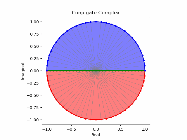
次いでcos(θ)曲線の導入。表裏の入れ替わりをプログラムで補正する必要がありません。

import math as m
import cmath as c
import numpy as num
from matplotlib import pyplot as plt
import matplotlib.animation as animation

# 複素円データ作成
c0=num.linspace(0,2*m.pi,61,endpoint = True)
c1=[]
for nm in range(len(c0)):
    c1.append(complex(m.cos(c0[nm]),m.sin(c0[nm])))
c2=num.array(c1)

# 回転テーブル(Rotation Ratio Table)作成
RRTa=num.linspace(0,2*m.pi,61,endpoint = True)
RRTb=[]
for nm in range(len(RRTa)):
    RRTb.append(m.cos(RRTa[nm]))
RRT=num.array(RRTb)

# 外周円データ作成
o0=num.linspace(0,2*m.pi,61,endpoint = True)
o1=[]
for nm in range(len(c0)):
    o1.append(complex(m.cos(o0[nm]),m.sin(o0[nm])))
o2=num.array(o1)

# 単位円データ作成
z=num.linspace(1,-1,31,endpoint = True)*(1+0j)
zp=z*(0+1j)
p0=[]
for nm in range(len(zp)):
    p0.append(c.exp(zp[nm]*m.pi/2)*(0-1j))
p1=num.array(p0)
# 共役複素数列(-)
m1=-p1[::-1]

# グラフ表示準備
plt.style.use('default')
fig = plt.figure()

# 関数定義
def Circle_Rotation(m):
    n=0
    plt.cla()
    #座標変換(jk)
    p2=[]
    for nm in range(len(p1)):
        p2.append(complex(p1[nm].real,p1[nm].imag*RRT[m]))
    p3=num.array(p2)
    m2=[]
    for nm in range(len(m1)):
        m2.append(complex(m1[nm].real,m1[nm].imag*RRT[m]))
    m3=num.array(m2)
    c3=[]
    for nm in range(len(c2)):
        c3.append(complex(c2[nm].real,c2[nm].imag*RRT[m]))
    c4=num.array(c3)
    #座標変換(wi)
    z2=[]
    for nm in range(len(z)):
        z2.append(z[nm]*c2[n])
    z3=num.array(z2)
    p4=[]
    for nm in range(len(p3)):
        p4.append(p3[nm]*c2[n])
    p5=num.array(p4)
    m4=[]
    for nm in range(len(m3)):
        m4.append(m3[nm]*c2[n])
    m5=num.array(m4)
    #スポーク描画
    for nm in range(len(c2)):
        plt.plot([0,c4[nm].real],[0,c4[nm].imag],color="gray",lw=0.5);

    #円描画
    plt.plot(o2.real,o2.imag,color="black")
    plt.plot(z3.real,z3.imag,color="green", marker=".")
    plt.plot(p5.real,p5.imag,color="red", marker=".")
    plt.plot(m5.real,m5.imag,color="blue", marker=".")
    plt.ylim([-1.1,1.1])
    plt.xlim([-1.1,1.1])
    plt.title("Conjugate Complex")
    plt.xlabel("Real")
    plt.ylabel("Imaginal")
    ax = fig.add_subplot(111)
    ax.set_aspect('equal', adjustable='box')
    #塗りつぶし
    p6=num.concatenate([p5,z3])
    m6=num.concatenate([m5,z3])
    plt.fill(p6.real,p6.imag,facecolor="red",alpha=0.5)
    plt.fill(m6.real,m6.imag,facecolor="blue",alpha=0.5)

ani = animation.FuncAnimation(fig, Circle_Rotation, interval=50,frames=60)
ani.save("output153.gif", writer="pillow")
円盤の回転がそれほど滑らかになった様に見えないのは、人間の視覚による補正能力の高さを意味しているのかもしれません。ちなみにこの垂直回転と上掲の水平回転と組み合わせたものが四元数(quaternion)$w+i+j+k$におけるortho-split/sympletic form表現となり、xyz軸から完全に離れた回転表現が可能となります。確かに言われてみれば緯度経度などにも採用されている三次元曲座標系において垂直角θは水平角φの半分しか使いませんが、この座標系では全周分使うのです。
Rで四元数
PythonでQuaternionを使う ~ numpy-quaternion ~
描画関数
import math as m
import cmath as c
import numpy as num
from matplotlib import pyplot as plt
import matplotlib.animation as animation

# 複素円データ作成
c0=num.linspace(0,2*m.pi,61,endpoint = True)
c1=[]
for nm in range(len(c0)):
    c1.append(complex(m.cos(c0[nm]),m.sin(c0[nm])))
c2=num.array(c1)

# 回転テーブル(Rotation Ratio Table)作成
RRTa=num.linspace(0,2*m.pi,61,endpoint = True)
RRTb=[]
for nm in range(len(RRTa)):
    RRTb.append(m.cos(RRTa[nm]))
RRT=num.array(RRTb)

# 外周円データ作成
o0=num.linspace(0,2*m.pi,61,endpoint = True)
o1=[]
for nm in range(len(c0)):
    o1.append(complex(m.cos(o0[nm]),m.sin(o0[nm])))
o2=num.array(o1)

# 単位円データ作成
z=num.linspace(1,-1,31,endpoint = True)*(1+0j)
zp=z*(0+1j)
p0=[]
for nm in range(len(zp)):
    p0.append(c.exp(zp[nm]*m.pi/2)*(0-1j))
p1=num.array(p0)
# 共役複素数列(-)
m1=-p1[::-1]

# グラフ表示準備
plt.style.use('default')
fig = plt.figure()

# 関数定義
def Circle_Rotation(ind):
    plt.cla()
    n=TC_wi[ind]
    m=TC_jk[ind]
    #座標変換(jk)
    p2=[]
    for nm in range(len(p1)):
        p2.append(complex(p1[nm].real,p1[nm].imag*RRT[m]))
    p3=num.array(p2)
    m2=[]
    for nm in range(len(m1)):
        m2.append(complex(m1[nm].real,m1[nm].imag*RRT[m]))
    m3=num.array(m2)
    c3=[]
    for nm in range(len(c2)):
        c3.append(complex(c2[nm].real,c2[nm].imag*RRT[m]))
    c4=num.array(c3)
    #座標変換(wi)
    z2=[]
    for nm in range(len(z)):
        z2.append(z[nm]*c2[n])
    z3=num.array(z2)
    p4=[]
    for nm in range(len(p3)):
        p4.append(p3[nm]*c2[n])
    p5=num.array(p4)
    m4=[]
    for nm in range(len(m3)):
        m4.append(m3[nm]*c2[n])
    m5=num.array(m4)
    c5=[]
    for nm in range(len(c4)):
        c5.append(c4[nm]*c2[n])
    c6=num.array(c5)
    #スポーク描画
    for nm in range(len(c2)):
        plt.plot([0,c6[nm].real],[0,c6[nm].imag],color="gray",lw=0.5);

    #円描画
    plt.plot(o2.real,o2.imag,color="black")
    plt.plot(z3.real,z3.imag,color="green", marker=".")
    plt.plot(p5.real,p5.imag,color="red", marker=".")
    plt.plot(m5.real,m5.imag,color="blue", marker=".")
    plt.ylim([-1.1,1.1])
    plt.xlim([-1.1,1.1])
    plt.title("Conjugate Complex")
    plt.xlabel("Real")
    plt.ylabel("Imaginal")
    ax = fig.add_subplot(111)
    ax.set_aspect('equal', adjustable='box')
    #塗りつぶし
    p6=num.concatenate([p5,z3])
    m6=num.concatenate([m5,z3])
    plt.fill(p6.real,p6.imag,facecolor="red",alpha=0.5)
    plt.fill(m6.real,m6.imag,facecolor="blue",alpha=0.5)
角度θと角度φの角速度wの比率が1:2の時

# タイムコード(Time Code)
TC_wi=num.arange(0,60)
TC_jk_a=num.arange(0,60,2)
TC_jk=num.concatenate([TC_jk_a,TC_jk_a])

ani = animation.FuncAnimation(fig, Circle_Rotation, interval=50,frames=60)
ani.save("output161.gif", writer="pillow")
角度θと角度φの角速度wの比率が1:4の時

# タイムコード(Time Code)
TC_wi=num.arange(0,60)
TC_jk_a=num.arange(0,60,4)
TC_jk=num.concatenate([TC_jk_a,TC_jk_a,TC_jk_a,TC_jk_a])

ani = animation.FuncAnimation(fig, Circle_Rotation, interval=50,frames=60)
ani.save("output162.gif", writer="pillow")
純虚数部に「補助線」を追加する。
ところで前段落の最後の二つのアニメーションはリサージュ曲線を描いているはずなのですが、R時代に試した様に「補助線」がないと認識が難しいのです。
描画関数
import math as m
import cmath as c
import numpy as num
from matplotlib import pyplot as plt
import matplotlib.animation as animation

# 複素円データ作成(外周データを兼ねる)
c0=num.linspace(0,2*m.pi,61,endpoint = True)
c1=[]
for nm in range(len(c0)):
    c1.append(complex(m.cos(c0[nm]),m.sin(c0[nm])))
c2=num.array(c1)

# 回転テーブル(Rotation Ratio Table)作成
RRTa=num.linspace(0,2*m.pi,61,endpoint = True)
RRTb=[]
for nm in range(len(RRTa)):
    RRTb.append(m.cos(RRTa[nm]))
RRT=num.array(RRTb)

# 対蹠線テーブル(AntiPodes Table)作成
APTa=num.linspace(0,2*m.pi,61,endpoint = True)
APTb=[]
for nm in range(len(APTa)):
    APTb.append(m.sin(APTa[nm]))
APT=num.array(APTb)

# 単位円データ作成
z=num.linspace(1,-1,31,endpoint = True)*(1+0j)
zp=z*(0+1j)
p0=[]
for nm in range(len(zp)):
    p0.append(c.exp(zp[nm]*m.pi/2)*(0-1j))
p1=num.array(p0)
# 共役複素数列(-)
m1=-p1[::-1]

# グラフ表示準備
plt.style.use('default')
fig = plt.figure()

# 関数定義
def Circle_Rotation(ind):
    plt.cla()
    n=TC_wi[ind]
    m=TC_jk[ind]
    #座標変換(jk)
    p2=[]
    for nm in range(len(p1)):
        p2.append(complex(p1[nm].real,p1[nm].imag*RRT[m]))
    p3=num.array(p2)
    m2=[]
    for nm in range(len(m1)):
        m2.append(complex(m1[nm].real,m1[nm].imag*RRT[m]))
    m3=num.array(m2)
    c3=[]
    for nm in range(len(c2)):
        c3.append(complex(c2[nm].real,c2[nm].imag*RRT[m]))
    c4=num.array(c3)
    apt1=complex(0,APT[m])
    #座標変換(wi)
    z2=[]
    for nm in range(len(z)):
        z2.append(z[nm]*c2[n])
    z3=num.array(z2)
    p4=[]
    for nm in range(len(p3)):
        p4.append(p3[nm]*c2[n])
    p5=num.array(p4)
    m4=[]
    for nm in range(len(m3)):
        m4.append(m3[nm]*c2[n])
    m5=num.array(m4)
    c5=[]
    for nm in range(len(c4)):
        c5.append(c4[nm]*c2[n])
    c6=num.array(c5)
    apt2=apt1*c2[n]
    #スポーク描画
    for nm in range(len(c2)):
        plt.plot([0,c6[nm].real],[0,c6[nm].imag],color="gray",lw=0.5);

    #円描画
    plt.plot(c2.real,c2.imag,color="black")
    plt.plot(z3.real,z3.imag,color="green", marker=".")
    plt.plot([0,apt2.real],[0,apt2.imag],color="green", marker="x")
    plt.plot(p5.real,p5.imag,color="red", marker=".")
    plt.plot(m5.real,m5.imag,color="blue", marker=".")
    plt.ylim([-1.1,1.1])
    plt.xlim([-1.1,1.1])
    plt.title("Conjugate Complex")
    plt.xlabel("Real")
    plt.ylabel("Imaginal")
    ax = fig.add_subplot(111)
    ax.set_aspect('equal', adjustable='box')
    #塗りつぶし
    p6=num.concatenate([p5,z3])
    m6=num.concatenate([m5,z3])
    plt.fill(p6.real,p6.imag,facecolor="red",alpha=0.5)
    plt.fill(m6.real,m6.imag,facecolor="blue",alpha=0.5)
jk軸の周期をwi軸の周期の倍に設定(角度θと角度φの角速度wの比率が1:2の時)

# タイムコード(Time Code)
TC_wi=num.arange(0,60)
TC_jk_a=num.arange(0,60,2)
TC_jk=num.concatenate([TC_jk_a,TC_jk_a])

ani = animation.FuncAnimation(fig, Circle_Rotation, interval=100,frames=60)
ani.save("output174.gif", writer="pillow")
逆にjk軸の周期をwi軸の周期の倍に設定(角度φと角度θの角速度wの比率が1:2の時)

# タイムコード(Time Code)
TC_jk=num.arange(0,60)
TC_wi_a=num.arange(0,60,2)
TC_wi=num.concatenate([TC_wi_a,TC_wi_a])

ani = animation.FuncAnimation(fig, Circle_Rotation, interval=100,frames=60)
ani.save("output176.gif", writer="pillow")
wi軸の角度θとjk軸の角度φの角速度wの比率が1:4の時

# タイムコード(Time Code)
TC_wi=num.arange(0,60)
TC_jk_a=num.arange(0,60,4)
TC_jk=num.concatenate([TC_jk_a,TC_jk_a,TC_jk_a,TC_jk_a])

ani = animation.FuncAnimation(fig, Circle_Rotation, interval=50,frames=60)
ani.save("output177.gif", writer="pillow")
逆にwi軸の角度φとjk軸の角度θの角速度wの比率が1:4の時

# タイムコード(Time Code)
TC_jk=num.arange(0,60)
TC_wi_a=num.arange(0,60,4)
TC_wi=num.concatenate([TC_wi_a,TC_wi_a,TC_wi_a,TC_wi_a])

ani = animation.FuncAnimation(fig, Circle_Rotation, interval=100,frames=60)
ani.save("output176.gif", writer="pillow")
結果が同じになりませんね。「四元数は可換ではない」とはこう事です。ちなみに…
j=0,k=0の時のwi軸の回転(+方向)

# タイムコード(Time Code)
TC_wi=num.arange(0,60)
TC_jk=num.repeat(0,60)

ani = animation.FuncAnimation(fig, Circle_Rotation, interval=100,frames=60)
ani.save("output178.gif", writer="pillow")
j=0,k=0の時のwi軸の回転(-方向)

# タイムコード(Time Code)
TC=num.arange(0,60)
TC_wi=TC[::-1]
TC_jk=num.repeat(0,60)

ani = animation.FuncAnimation(fig, Circle_Rotation, interval=100,frames=60)
ani.save("output195.gif", writer="pillow")
この様に水平回転の向きは繰り返し再生しても人間の肉眼に「反時計回り」「時計回り」を峻別する事が可能です。ならば以下の場合は?
i=0の時のjk軸の回転(+方向)

# タイムコード(Time Code)
TC_jk=num.arange(0,60)
TC_wi=num.repeat(0,60)

ani = animation.FuncAnimation(fig, Circle_Rotation, interval=100,frames=60)
ani.save("output196.gif", writer="pillow")
i=0の時のjk軸の回転(-方向)

# タイムコード(Time Code)
TC=num.arange(0,60)
TC_jk=TC[::-1]
TC_wi=num.repeat(0,60)

ani = animation.FuncAnimation(fig, Circle_Rotation, interval=100,frames=60)
ani.save("output197.gif", writer="pillow")
プログラムを眺めても、繰り返し再生した場合に人間の肉眼に「反時計回り」と「時計回り」を峻別する決定的基準が欠けているのは明らかです(言葉の綾でなく本当にない)。さらに両者を合算する時の考え方に2通りあるのですが…
①位相+90度の場合
k軸の回転(+方向)。

# タイムコード(Time Code)
TC_wi=num.repeat(15,60)
TC_jk=num.arange(0,60)

ani = animation.FuncAnimation(fig, Circle_Rotation, interval=100,frames=60)
ani.save("output193.gif", writer="pillow")
k軸の回転(-方向)。

# タイムコード(Time Code)
TC=num.arange(0,60)
TC_jk=TC[::-1]
TC_wi=num.repeat(15,60)

ani = animation.FuncAnimation(fig, Circle_Rotation, interval=100,frames=60)
ani.save("output198.gif", writer="pillow")
②位相-90度の場合
k軸の回転(+方向)。

# タイムコード(Time Code)
TC_wi=num.repeat(45,60)
TC_jk=num.arange(0,60)

ani = animation.FuncAnimation(fig, Circle_Rotation, interval=100,frames=60)
ani.save("output194.gif", writer="pillow")
k軸の回転(−方向)。

# タイムコード(Time Code)
TC=num.arange(0,60)
TC_jk=TC[::-1]
TC_wi=num.repeat(45,60)

ani = animation.FuncAnimation(fig, Circle_Rotation, interval=100,frames=60)
ani.save("output199.gif", writer="pillow")
衝撃の紛らわしさ!!(繰り返し再生するうち、たちまち肉眼で識別不可能となる)。そこで以下の様に規約したのが四元数という訳です。
Rで球面幾何学】ハミルトンの四元数(Hamilton's Quaternion)は何を表しているのか?
i^2=j^2=k^2=ijk=-1\\
ij=k,jk=i,ki=j\\
ji=-k,kj=-i,ik=-j
'
| i | j | k | |
|---|---|---|---|
| i | -1 | -k | j |
| j | k | -1 | -i |
| k | -j | -i | -1 |
そんな感じで以下続報…