このページ / About this page
このページはMini Pupperを動かそうの1/6ページです。
This is page 1 of How to get Mini Pupper walking.
工具 / Tools
キットに同梱されている工具の他に、組み立てには以下の物が必要です。
In addition to the tools included in the kit, the following items are required for assembly
- ロックタイト / Loctite
ロックタイトはナットの緩みを防止しますが、緩みに気づいたときに締めれば良いので必須ではありません。ただ、後から締めるためには一部解体しなければならないものもありますので、極力固定しましょう。
Loctite prevents the nut from loosening, but it is not essential, as it can be tightened only when looseness is noticed. However, some of them have to be dismantled in order to be tightened later, so fix them as much as possible.
使用するボルト
(更新情報: Kickstarter版に合わせました)
| ボルト | 本数 | 使用箇所 |
|---|---|---|
| M2x5mm | 2x4=8 | ①+②, ⑤+⑥ |
| M2x8mm | 3x4=12 | ②+③, ④+⑦, ③+④ |
| M2x12mm | 1x4=4 | ⑤+⑦ |
| M2x14mm | 1x4=4 | ③+⑤ |
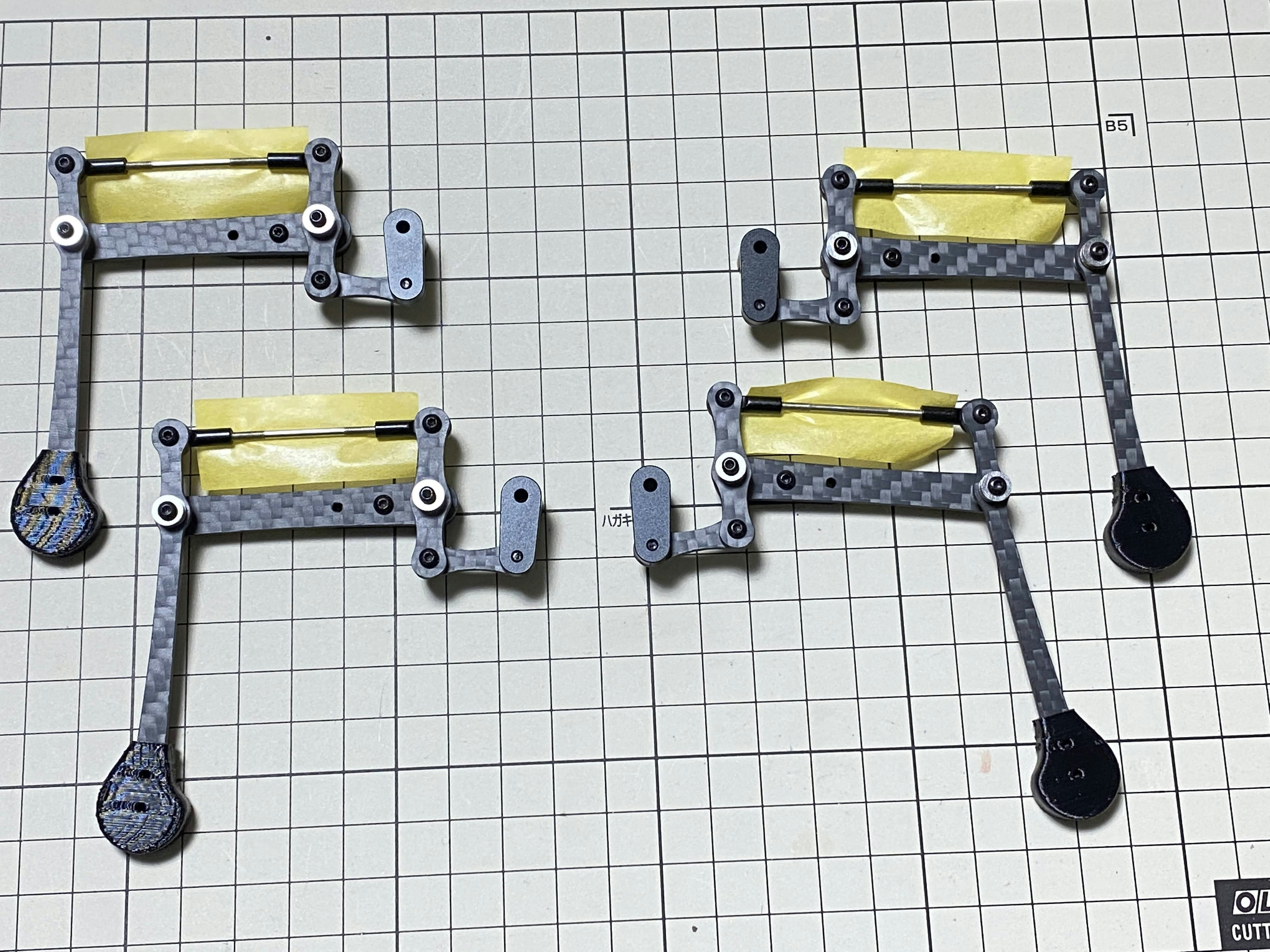
脚部 / Legs
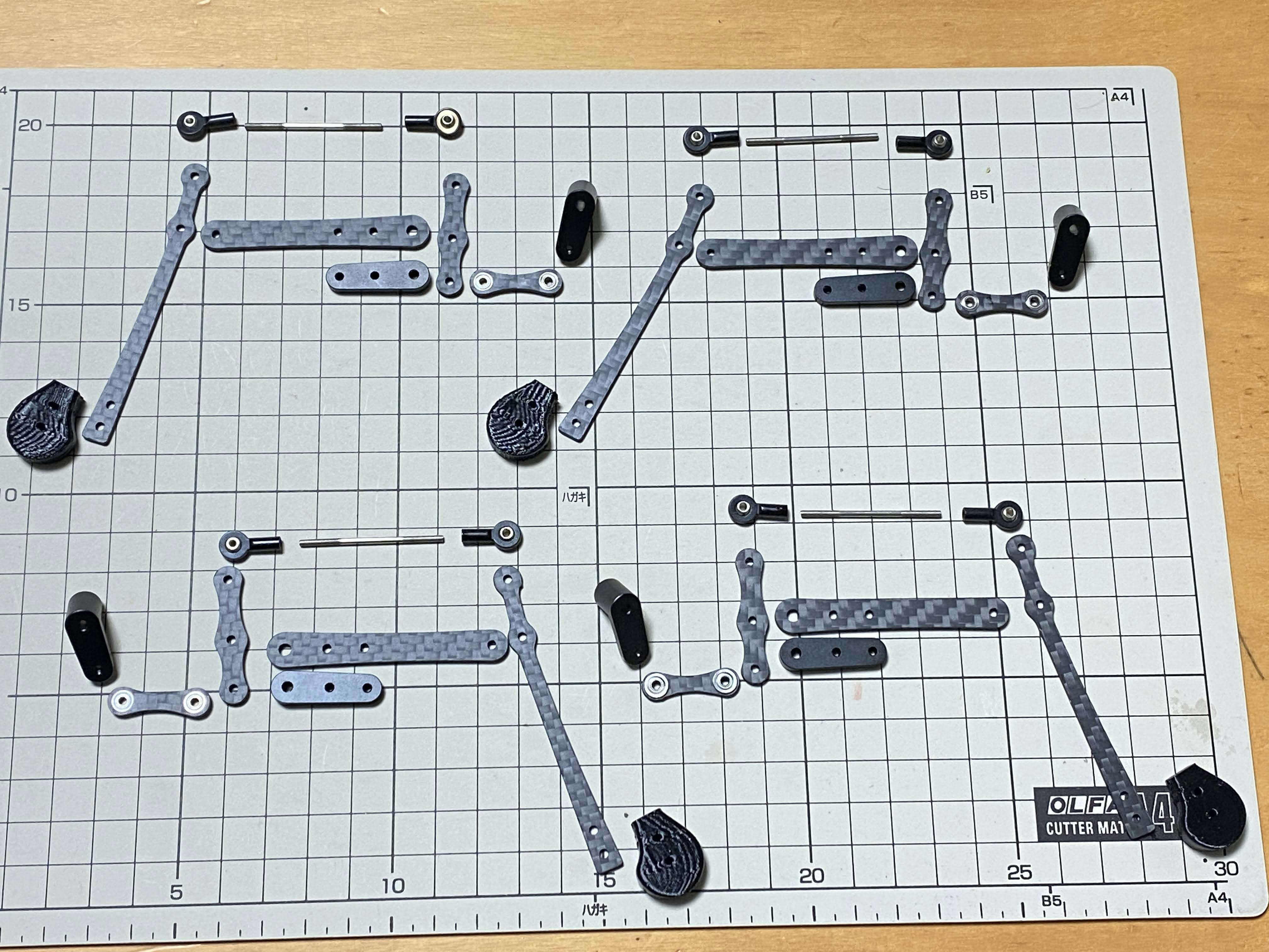
右側の脚 / right side legs
脚を4つ組み立てます。右の前と後ろは共通で、同様に左の前と後ろも共通です。では、右側の組み立て方を解説します。
Assemble the four legs. The front and back of the right side are the same, as are the front and back of the left side. Show you how to assemble the right side.
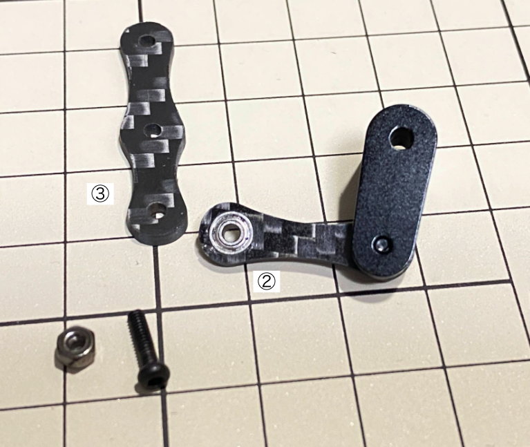
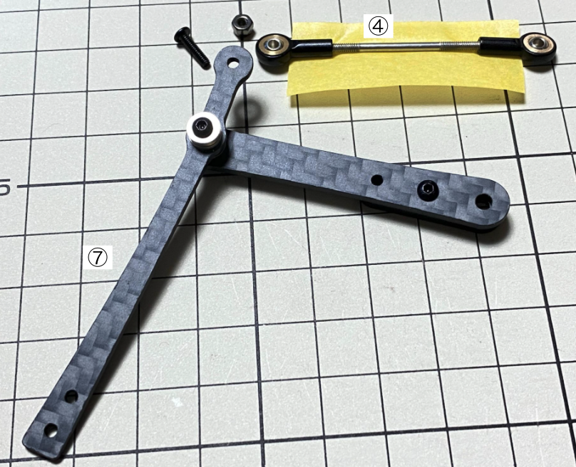
説明の便宜上、以下のようにパーツに番号を振りました。
I have numbered the parts as follows to explain them.
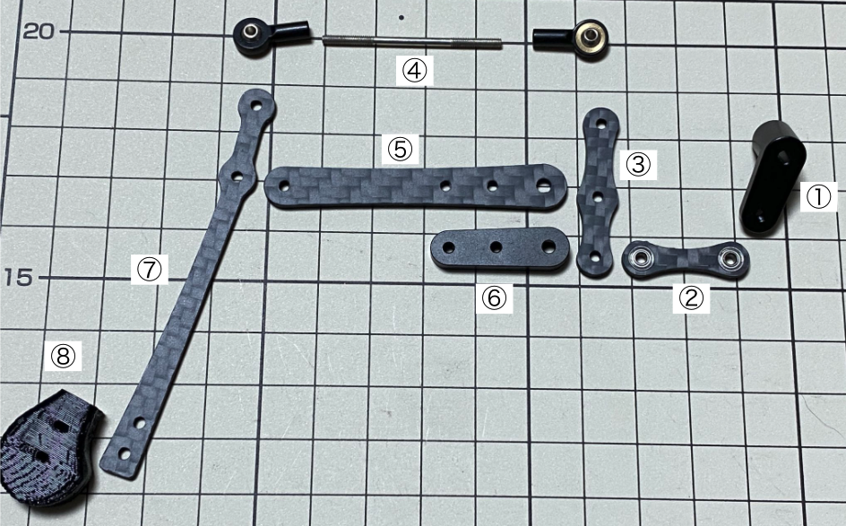
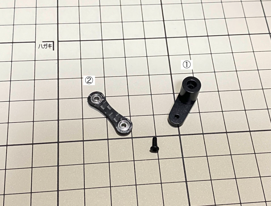
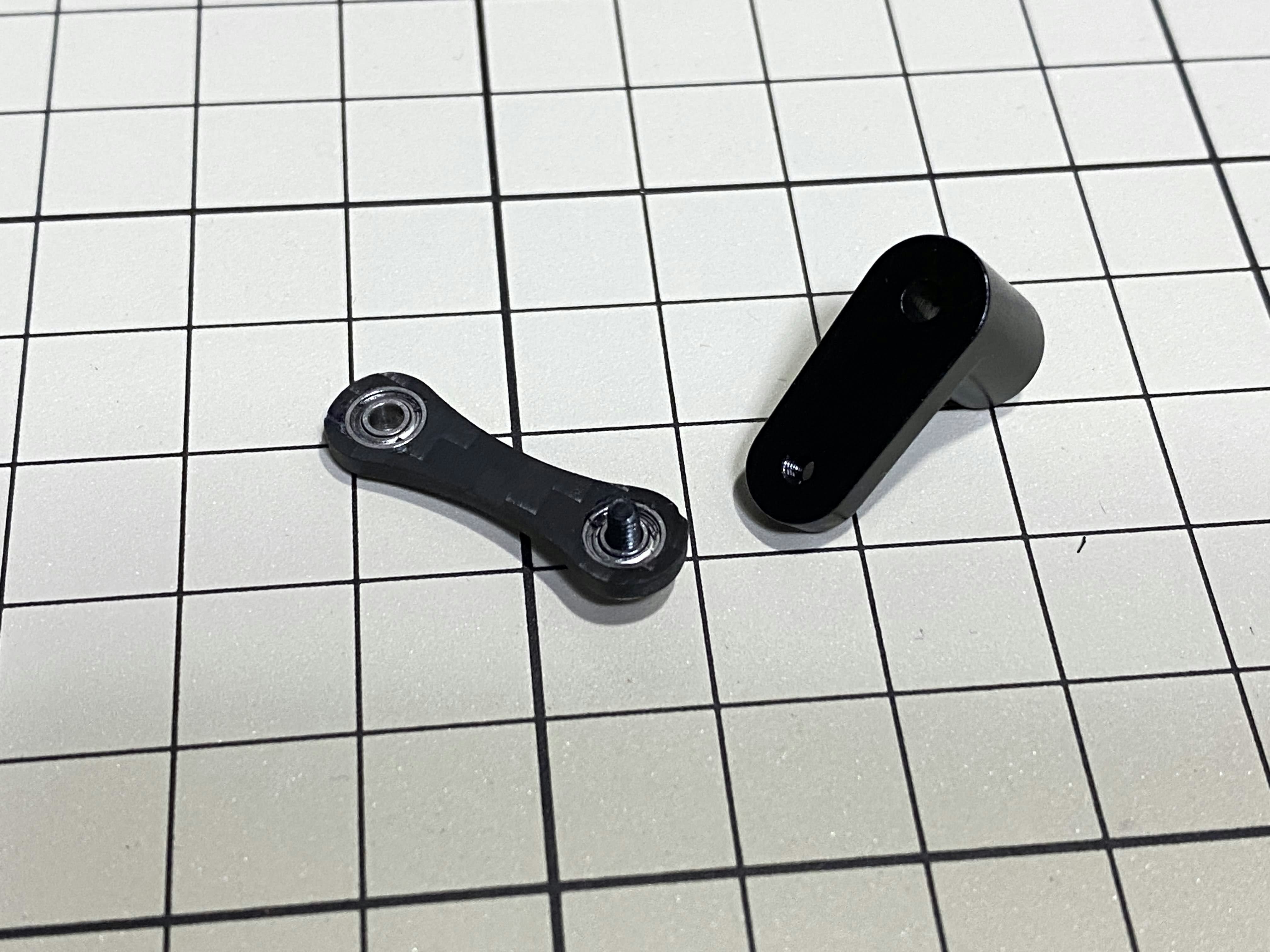
①と②の組み立て / Assemble ① and ②
M2x5mm のボルトを1つ使用します。ボルトは②の下から上に挿し、①の穴に挿し込んで締めます。②の表裏の向きに気をつけましょう。
Use one M2x5mm screw.The screw is inserted from the bottom of ② upwards and tightened by inserting them into the screw holes in ①. Be careful about the sides of ②.
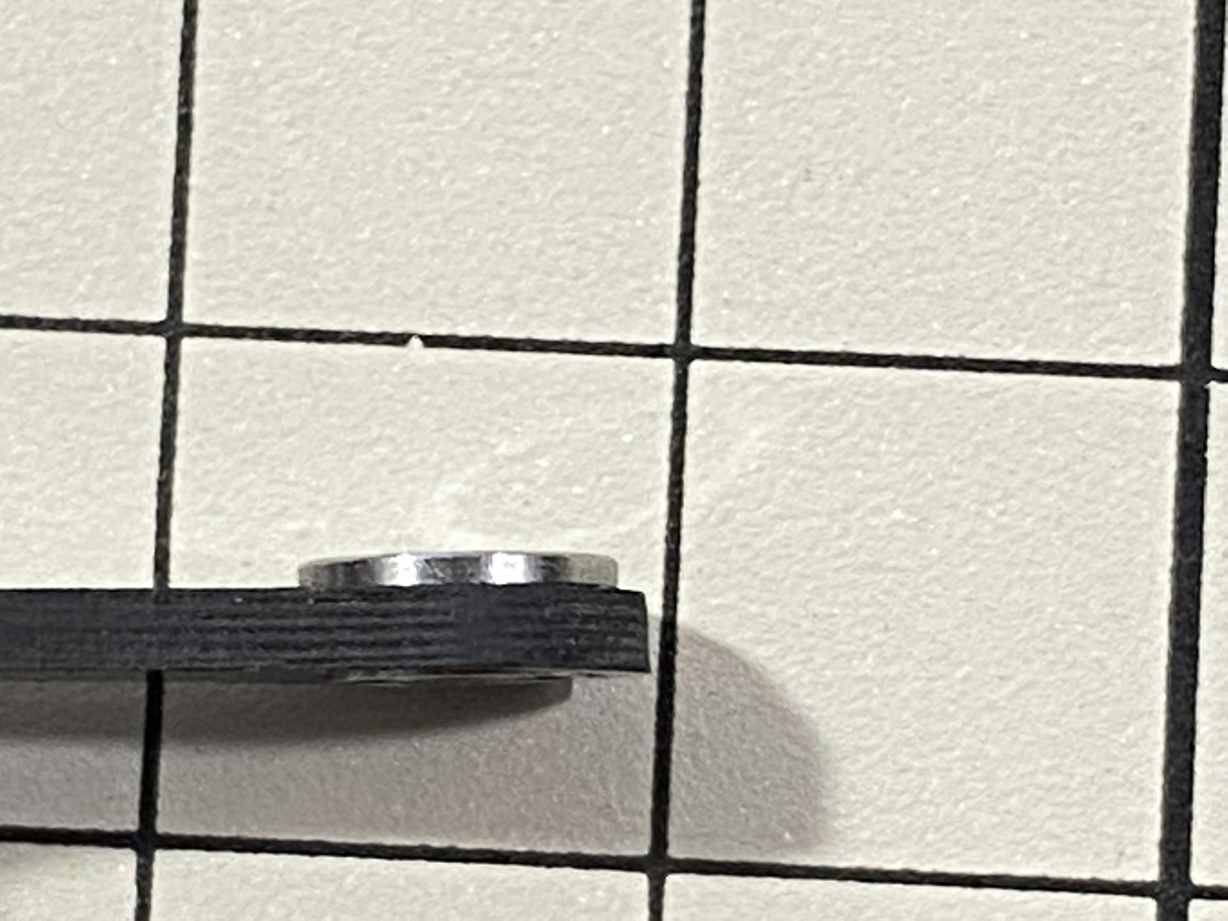
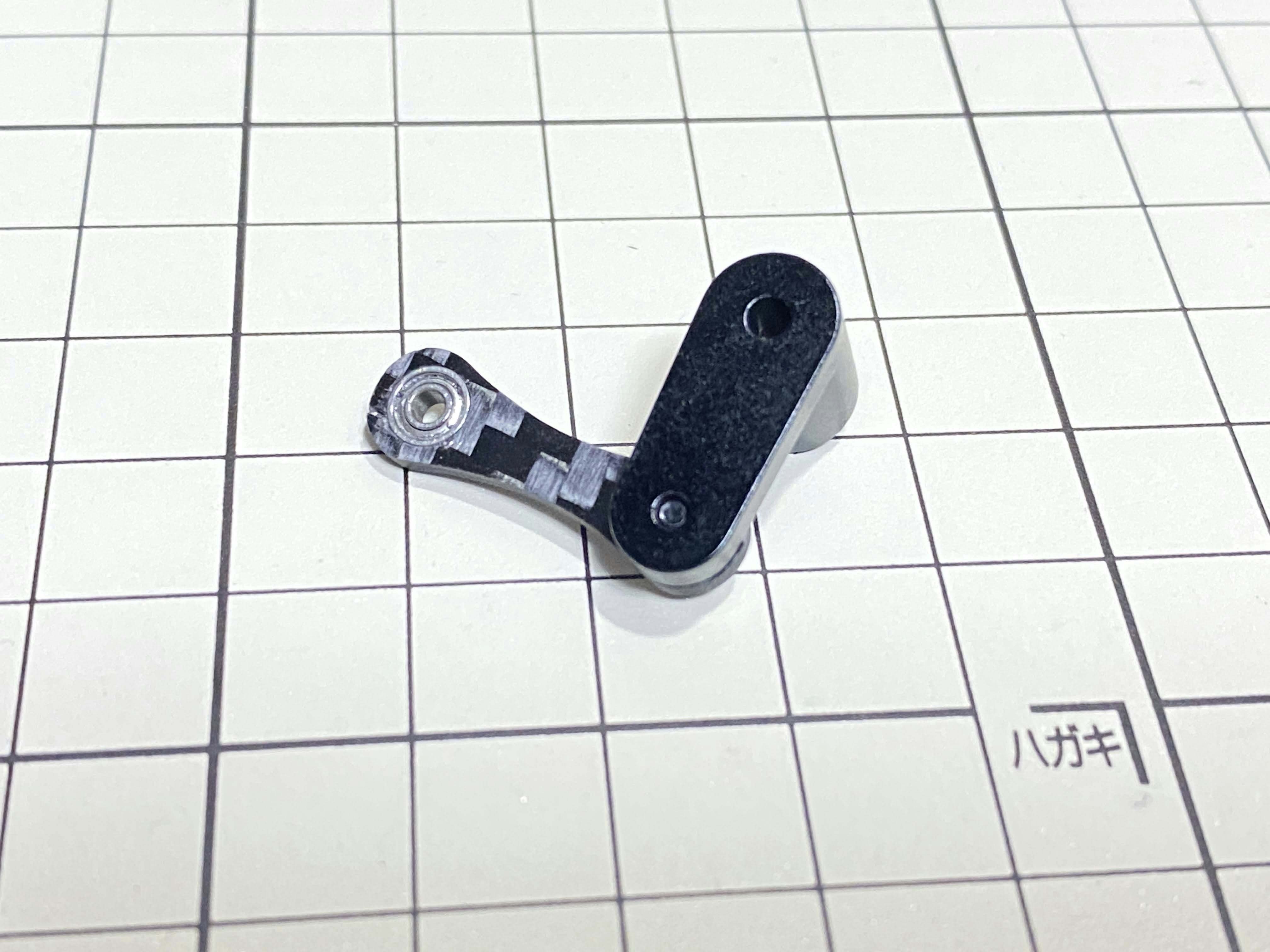
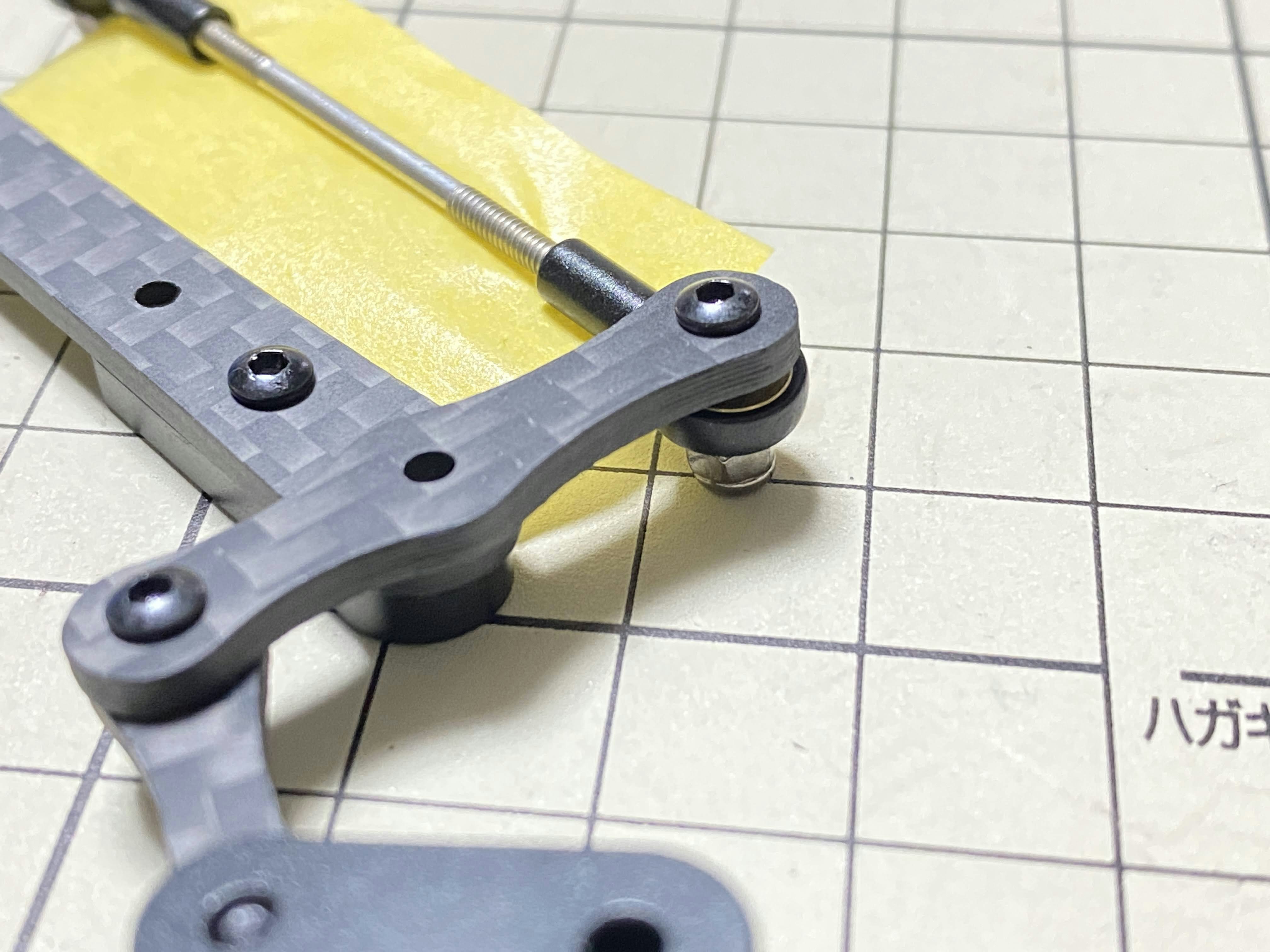
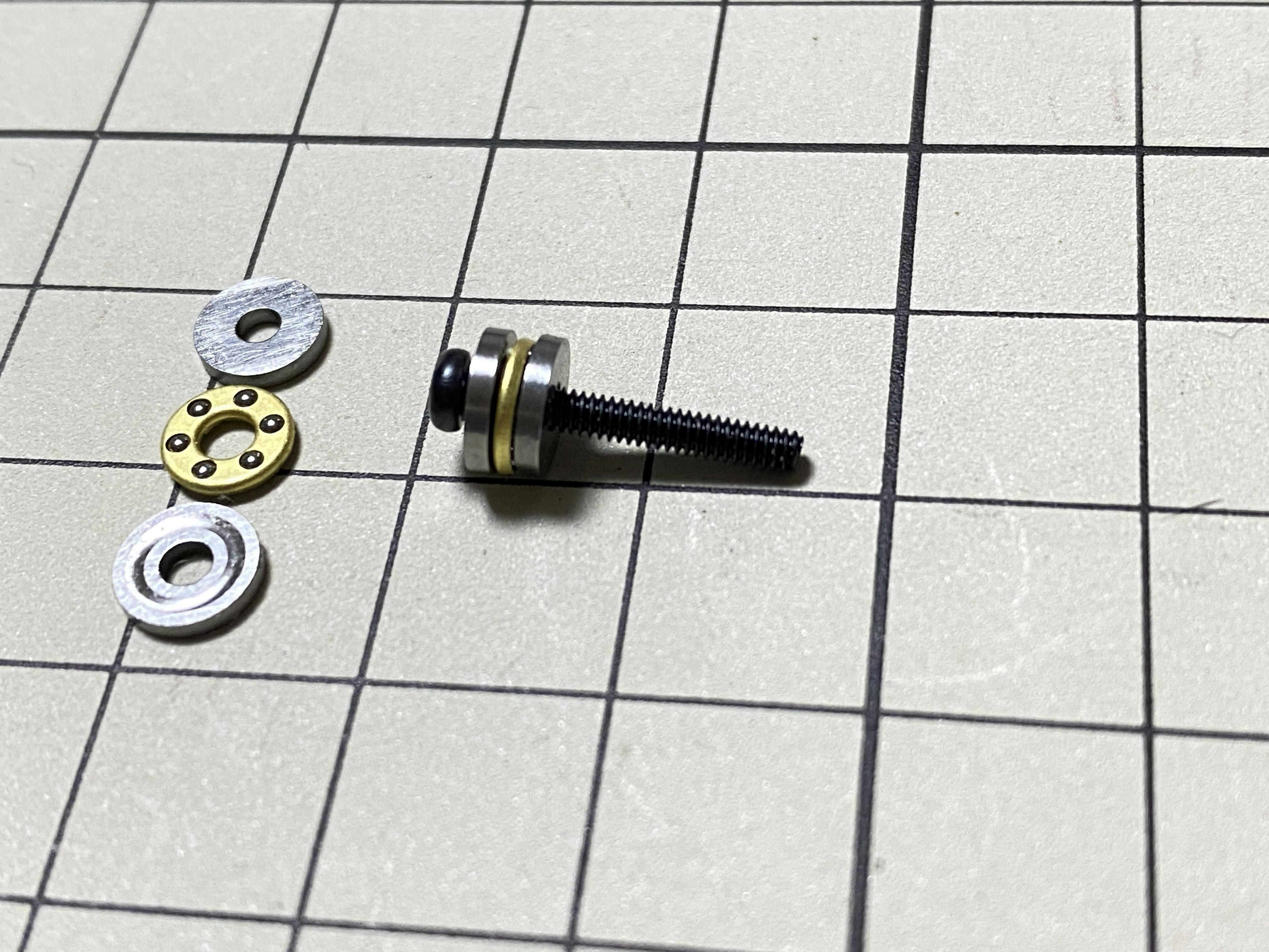
②のボールベアリング2個は奥まで挿し込み、下記の写真のように先が少し見える状態になっている必要があります。叩くなどして隙間をなくせば大丈夫です。
The two ballbearings in ② should be inserted all the way in and the end should be slightly visible as shown in the picture below. Tap the ball bearing and press it in without gaps.
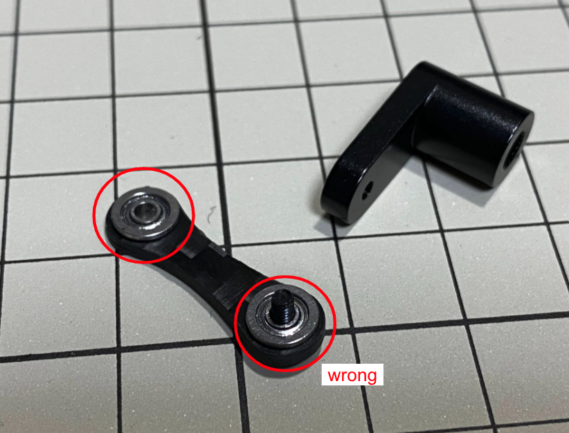
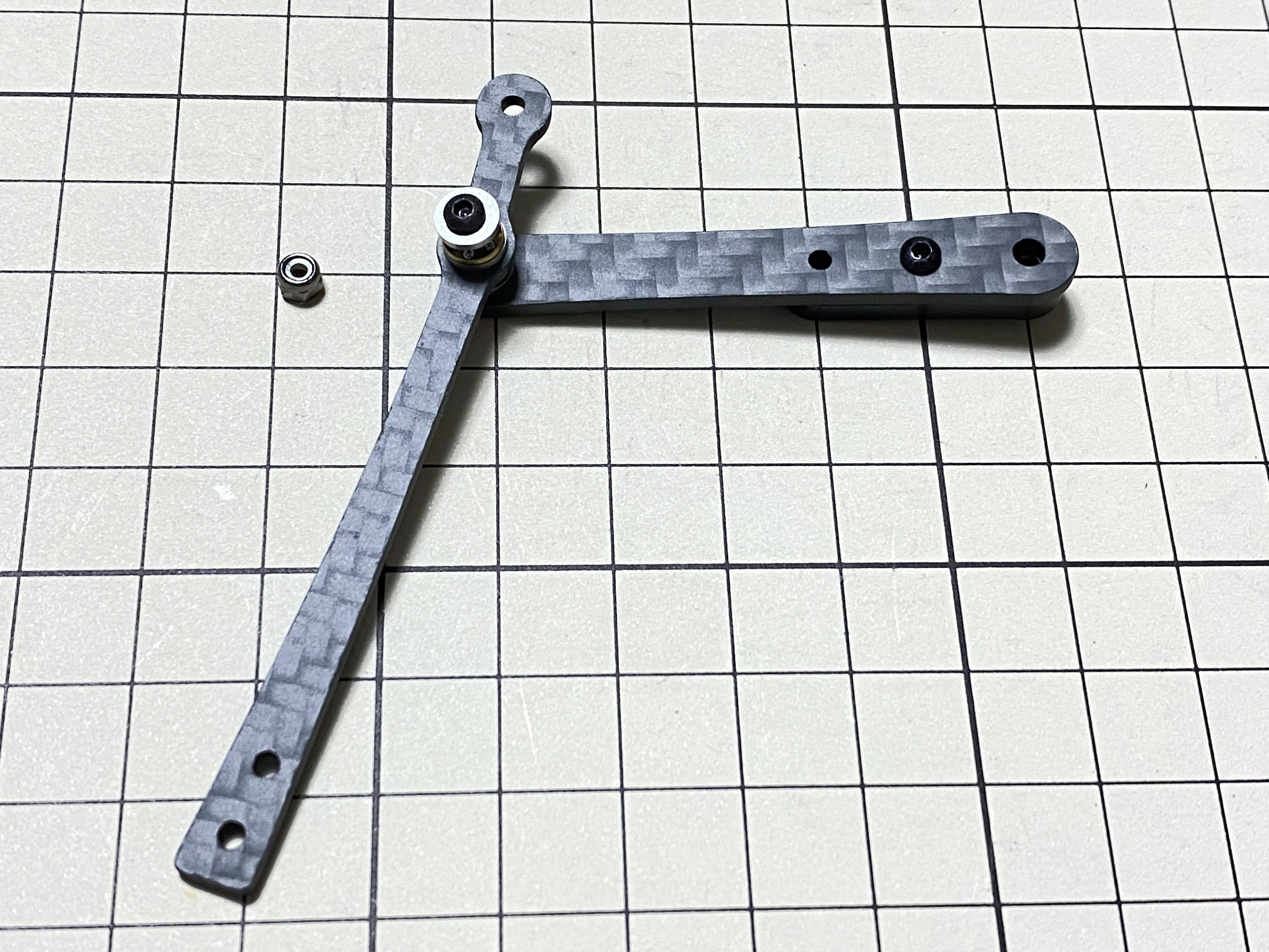
②と③の組み立て / Assemble ② and ③
M2x8mm のボルトを1つと M2 Locknutを使用します。ボルトを③の下から上に挿し、②を通し、ナットで締めます。③の部品の向きには気をつける必要があります。真ん中の穴の位置を良く見ましょう。
Use an M2x8mm screw and an M2 locknut. Insert the screw from the bottom to the top of ③, pass through ② and tighten with the nut. It is important to pay attention to the orientation of ③. Look carefully at the position of the hole in the middle.
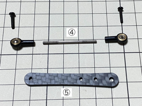
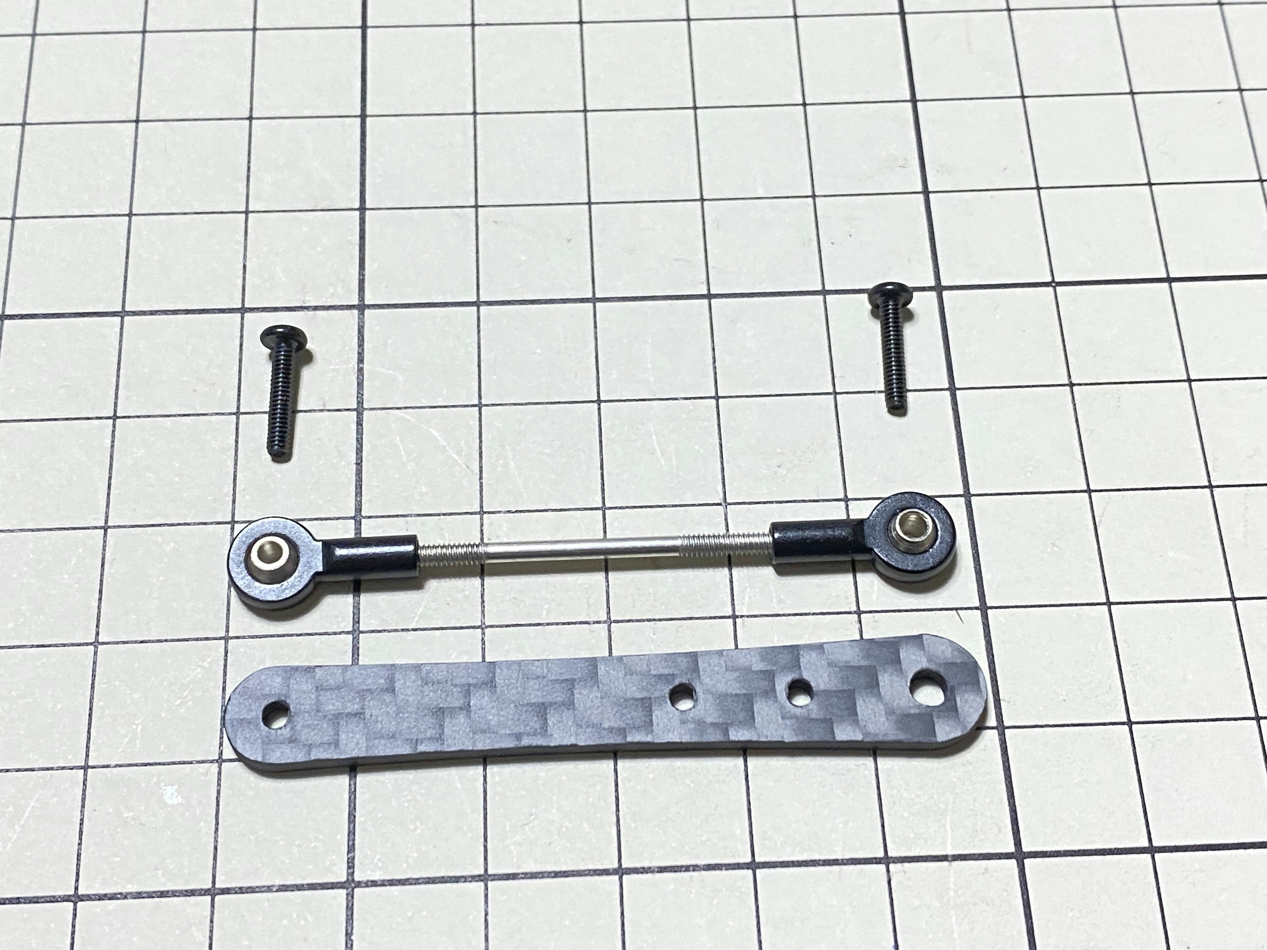
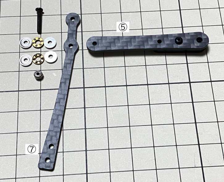
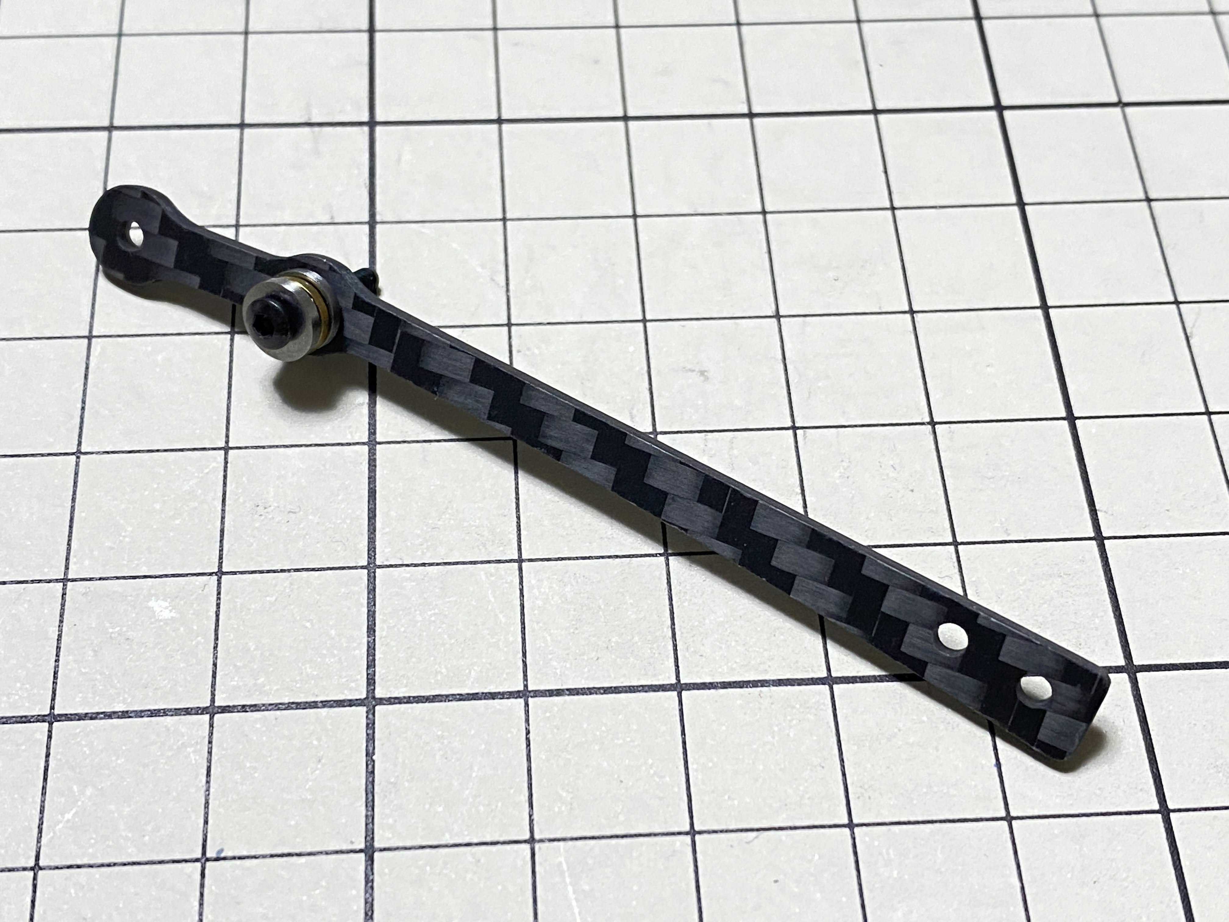
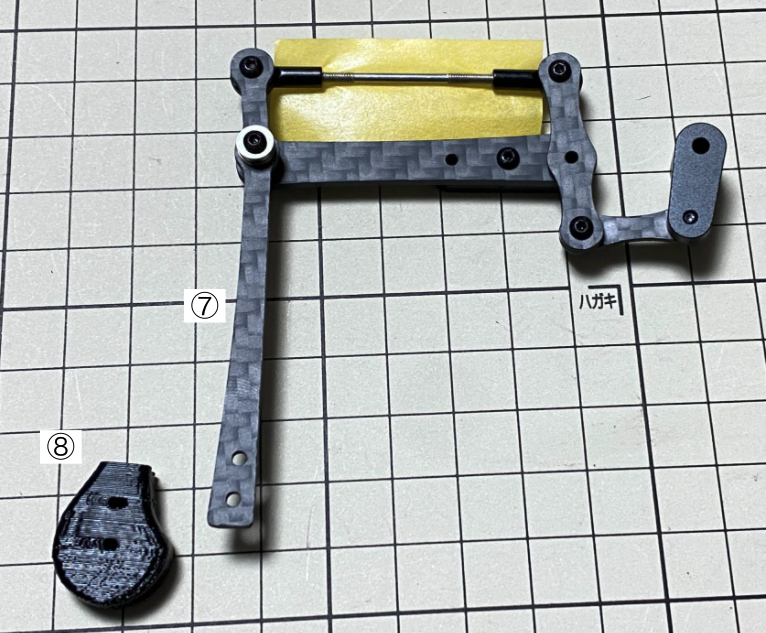
④の組み立てと長さの調整 / Assemble ④ and Adjust the length of ④
④を組み立てます。④の長さが⑤と一致している必要があります。長さを調整するとき、M2x15mmなどの長いボルトを2本使うと、長さが一致しているか確認しやすいです。長さの調整が完了したら、マスキングテープで回転しないように仮止めしておきましょう。最後に④以外はすべてバラしましょう。
Assemble ④. The length of ④ must match the length of ⑤. When adjusting the length, it is easier to use two long screws, e.g. M2x15mm, to make sure that the lengths match. Once the lengths have been adjusted, temporarily fix ④ with masking tape, and take apart all.
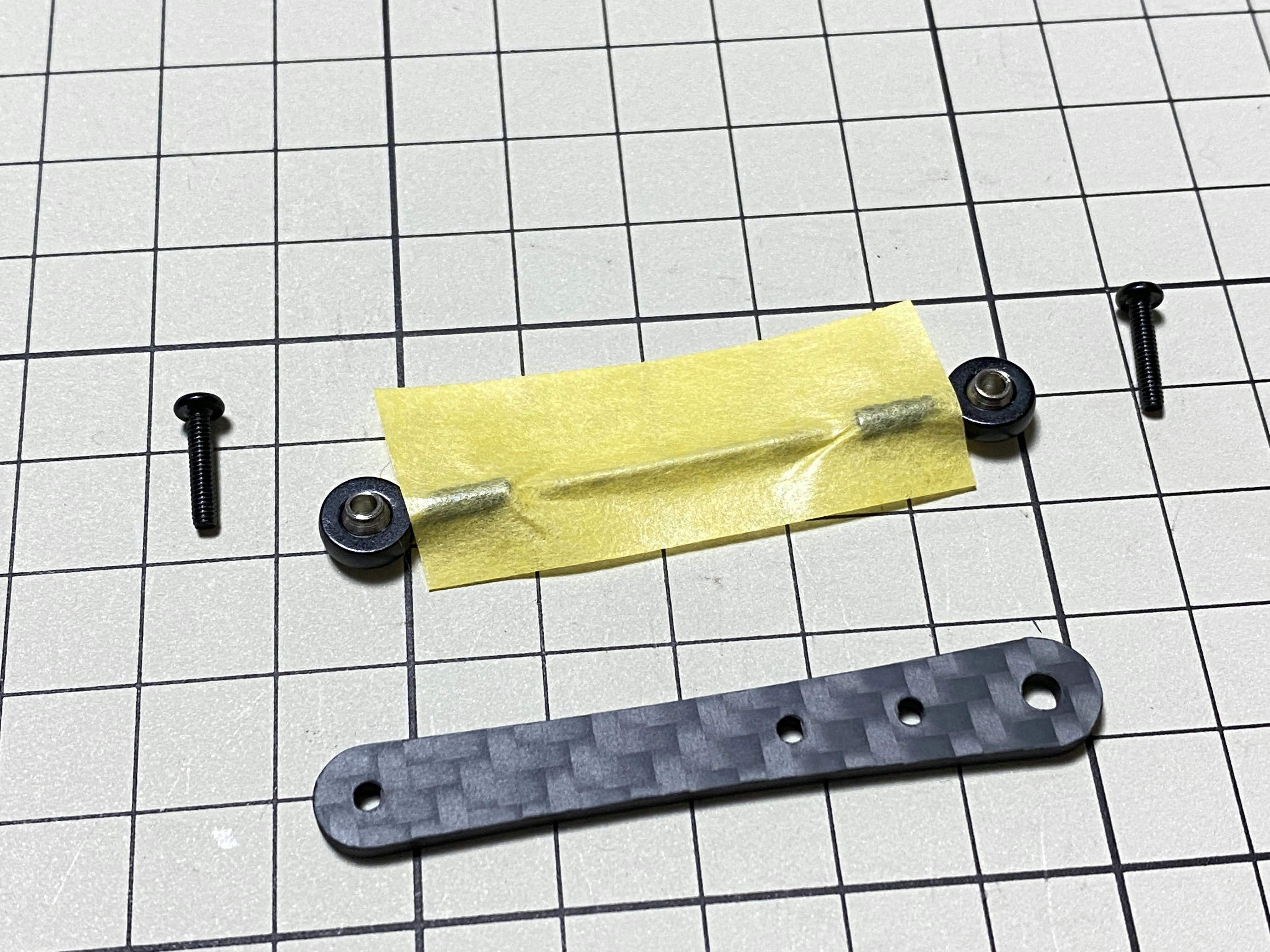
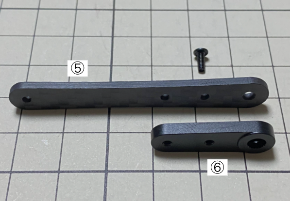
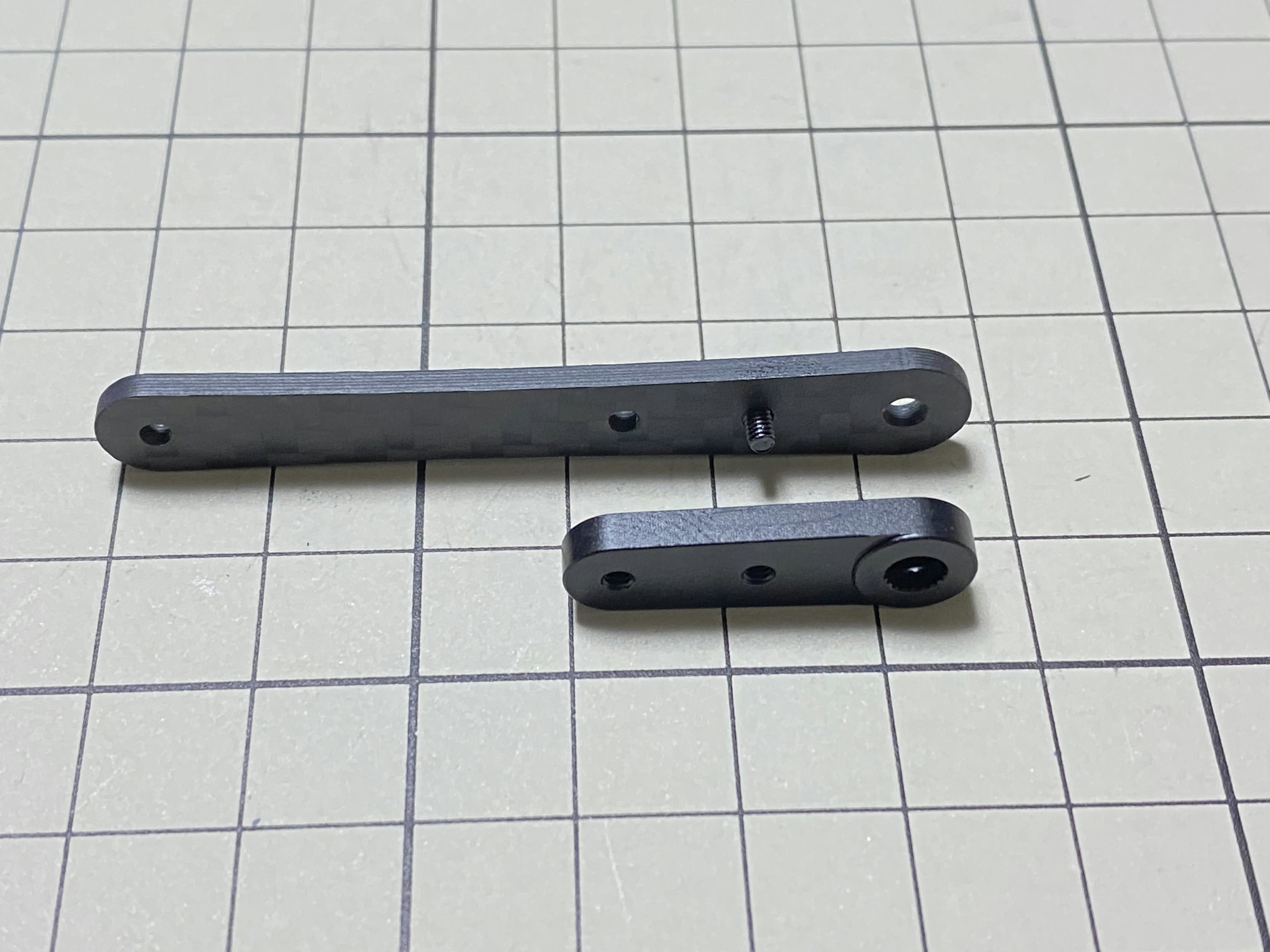
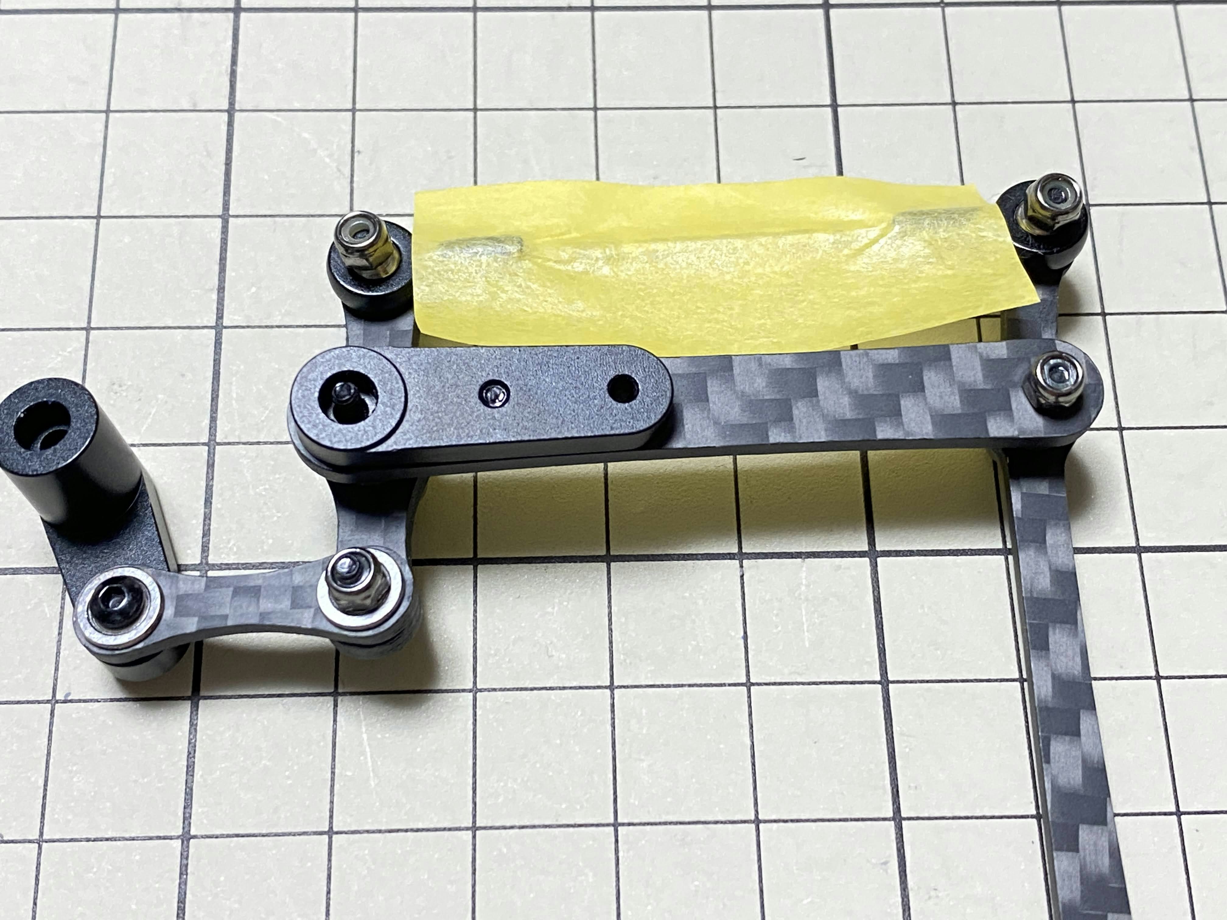
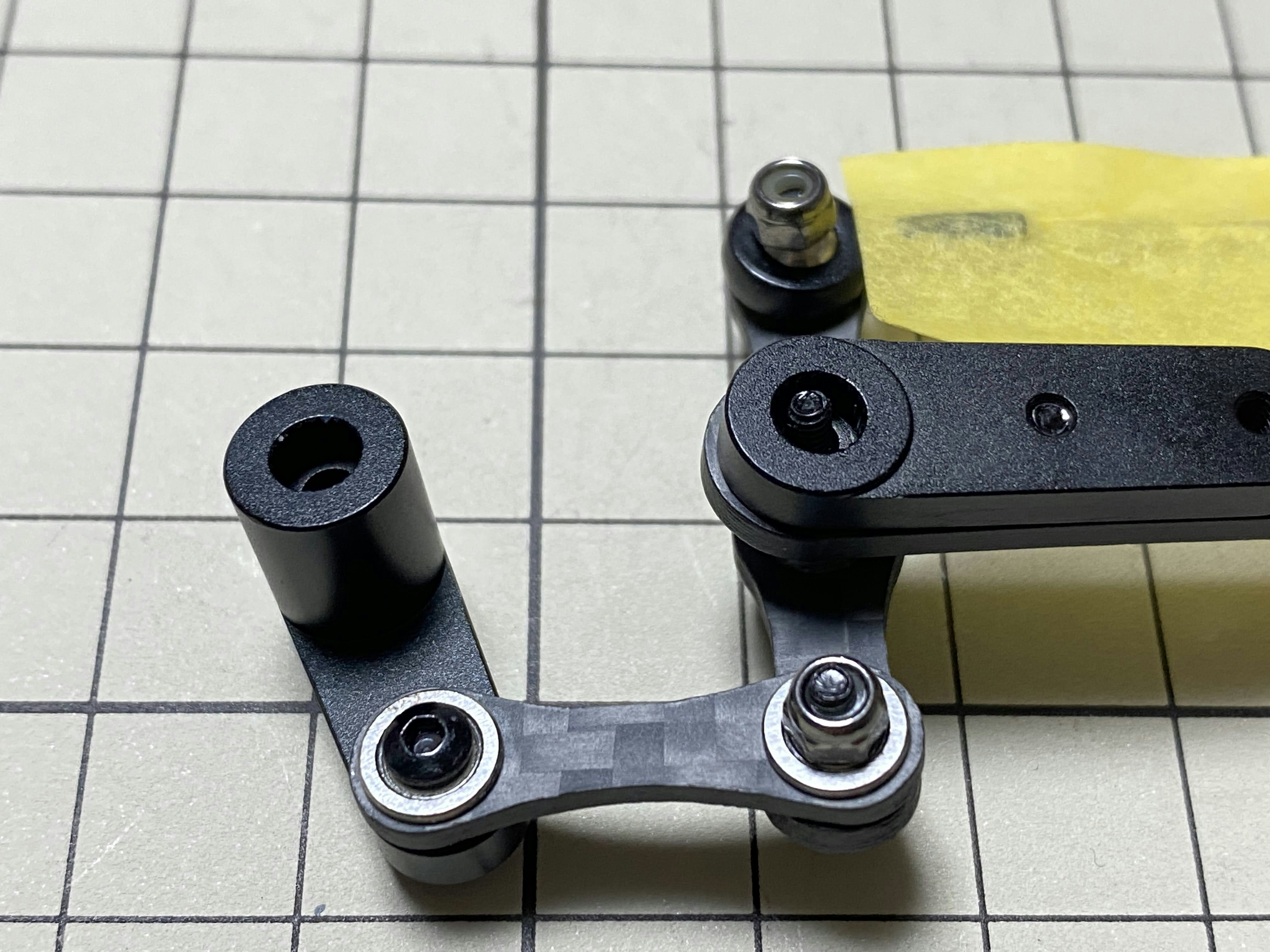
⑤と⑥の組み立て / Assemble ⑤ and ⑥
M2x5mmのボルトを1本使用します。⑤にボルトを挿し、⑥の穴に挿れて締めます。⑥は大きな穴がある方が表面側に来るように向けましょう。
Use two M2x5mm screws. Insert the screws into ⑤ first, insert them into the holes of ⑥, and tighten them. The large hole in ⑥ should be facing the surface.
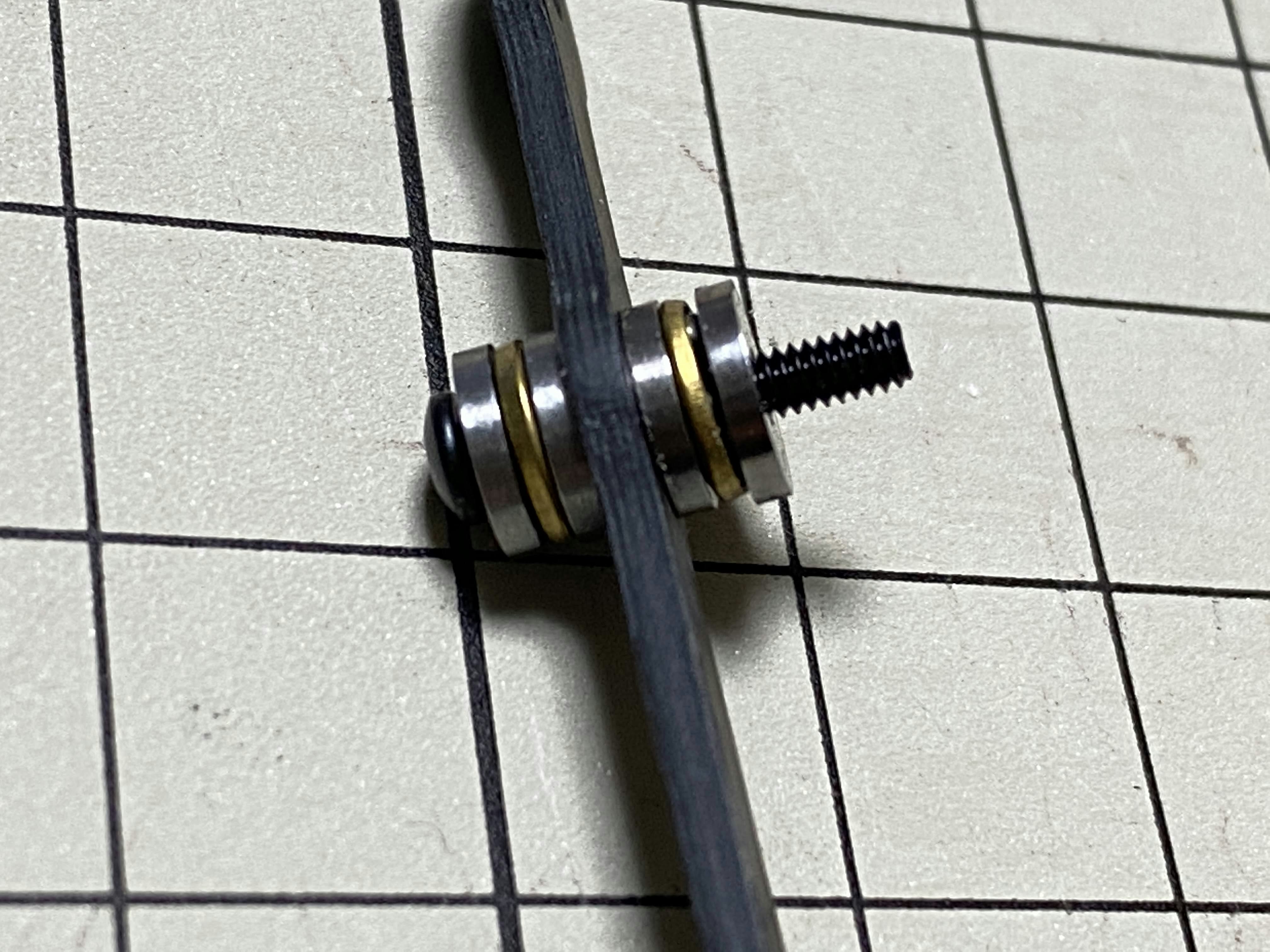
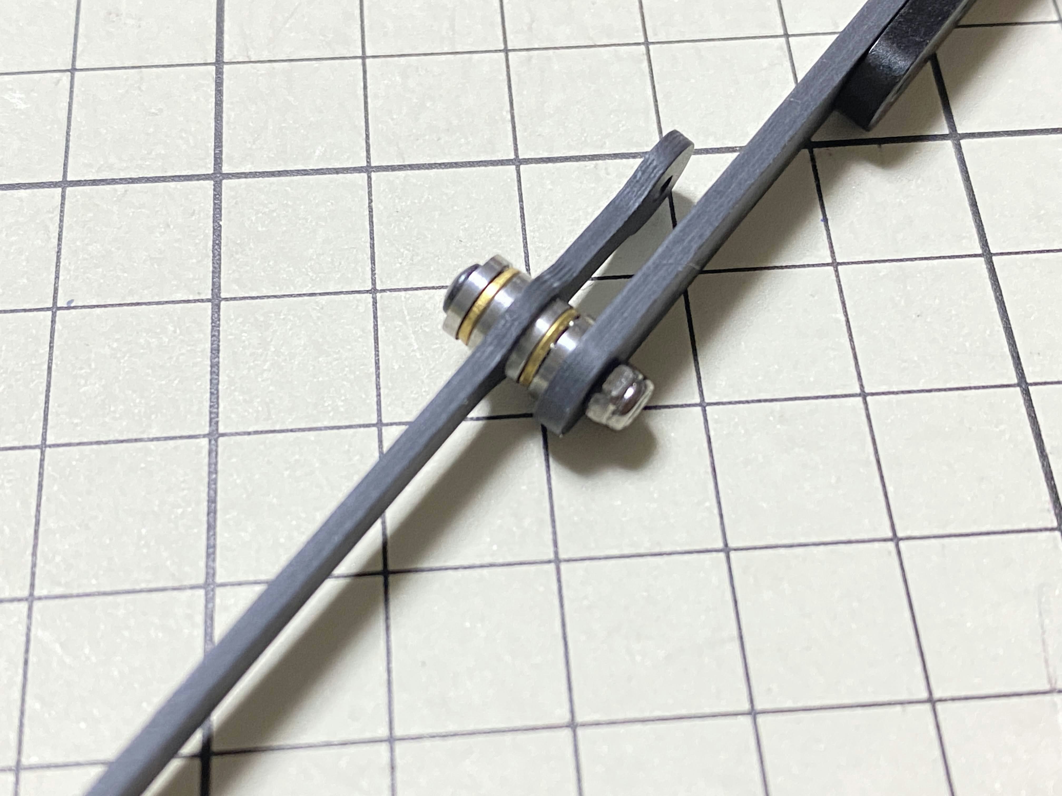
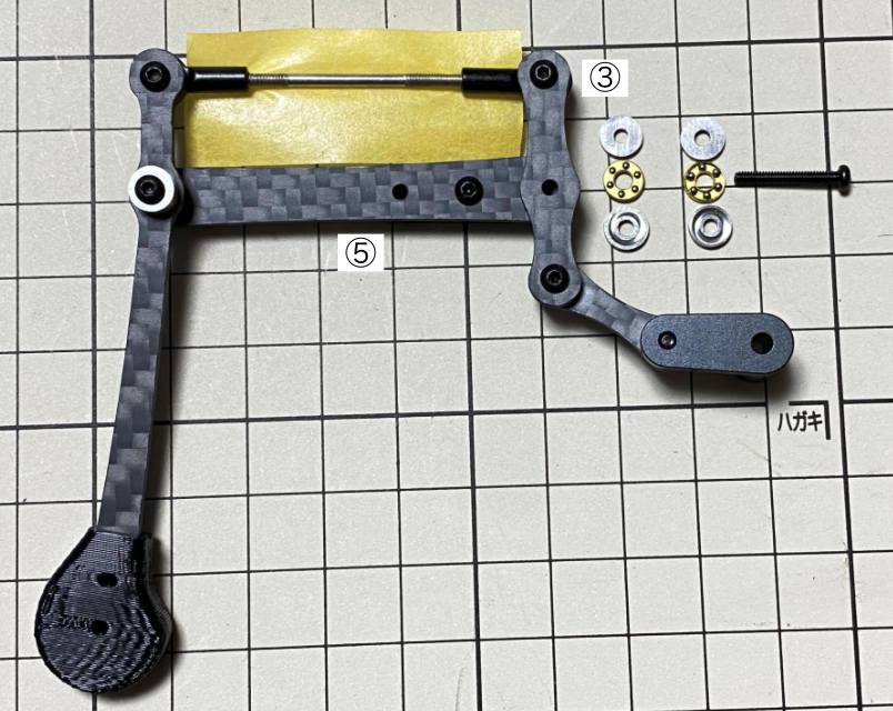
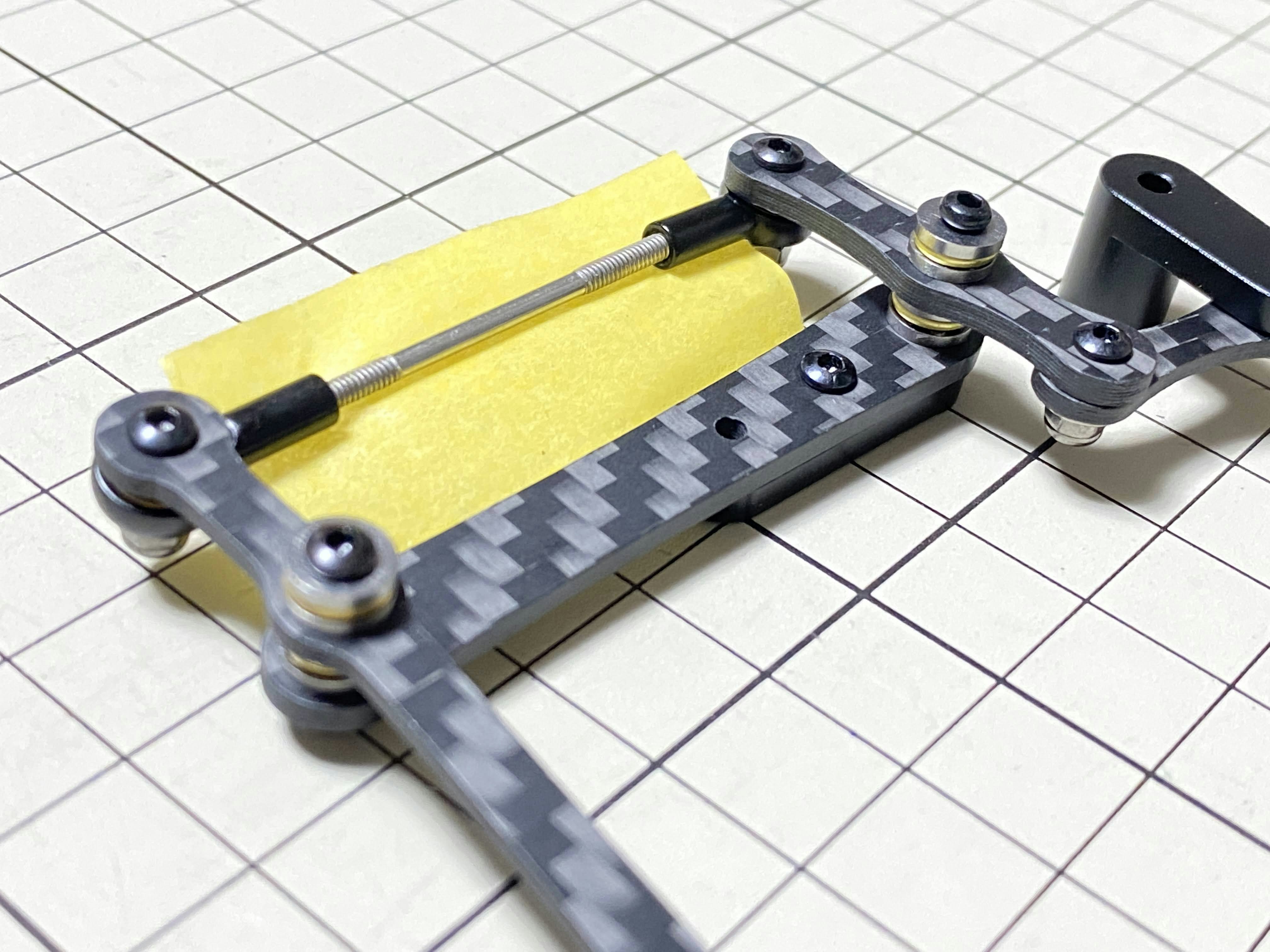
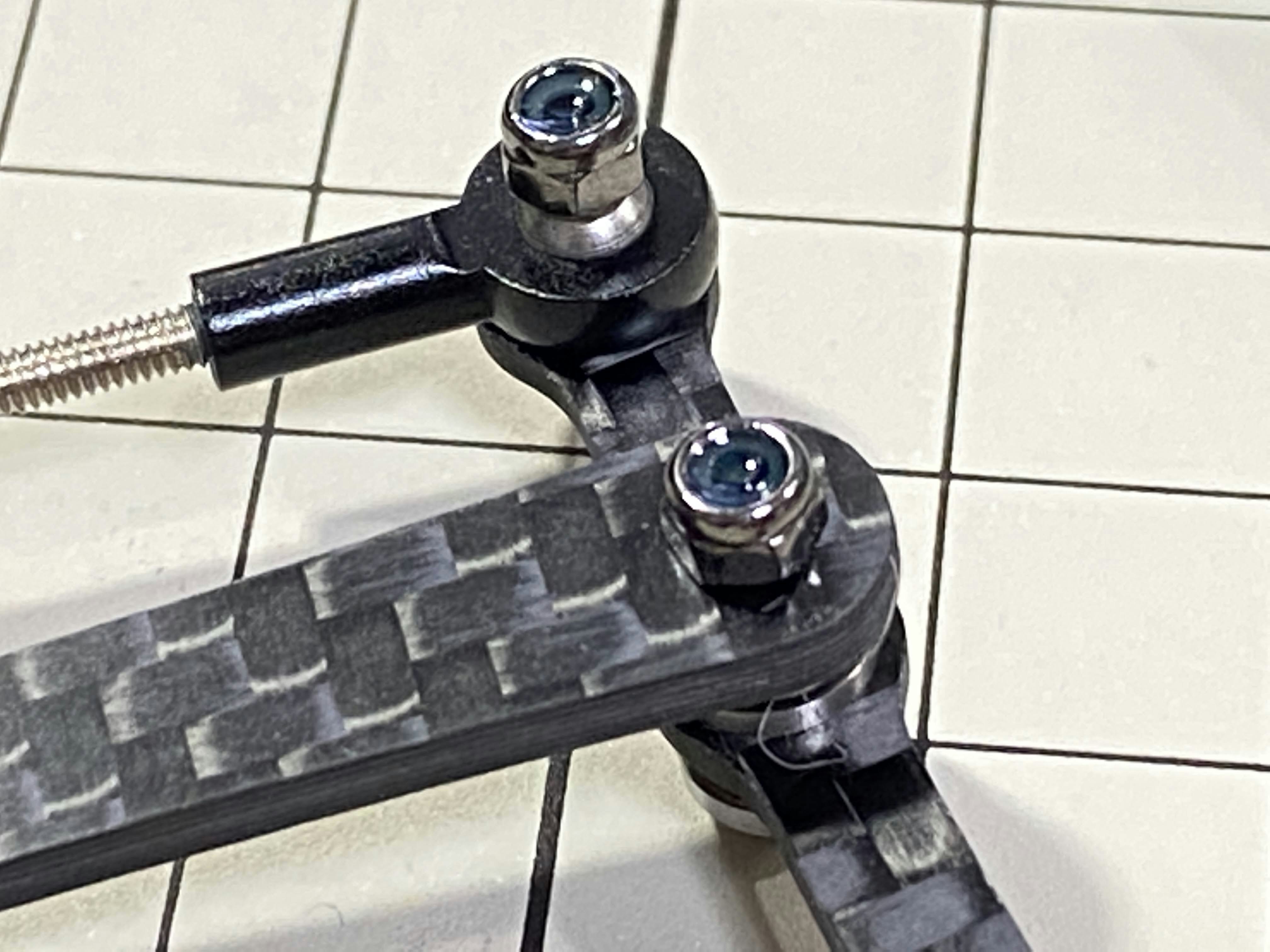
⑤と⑦の組み立て / Assemble ⑤ and ⑦
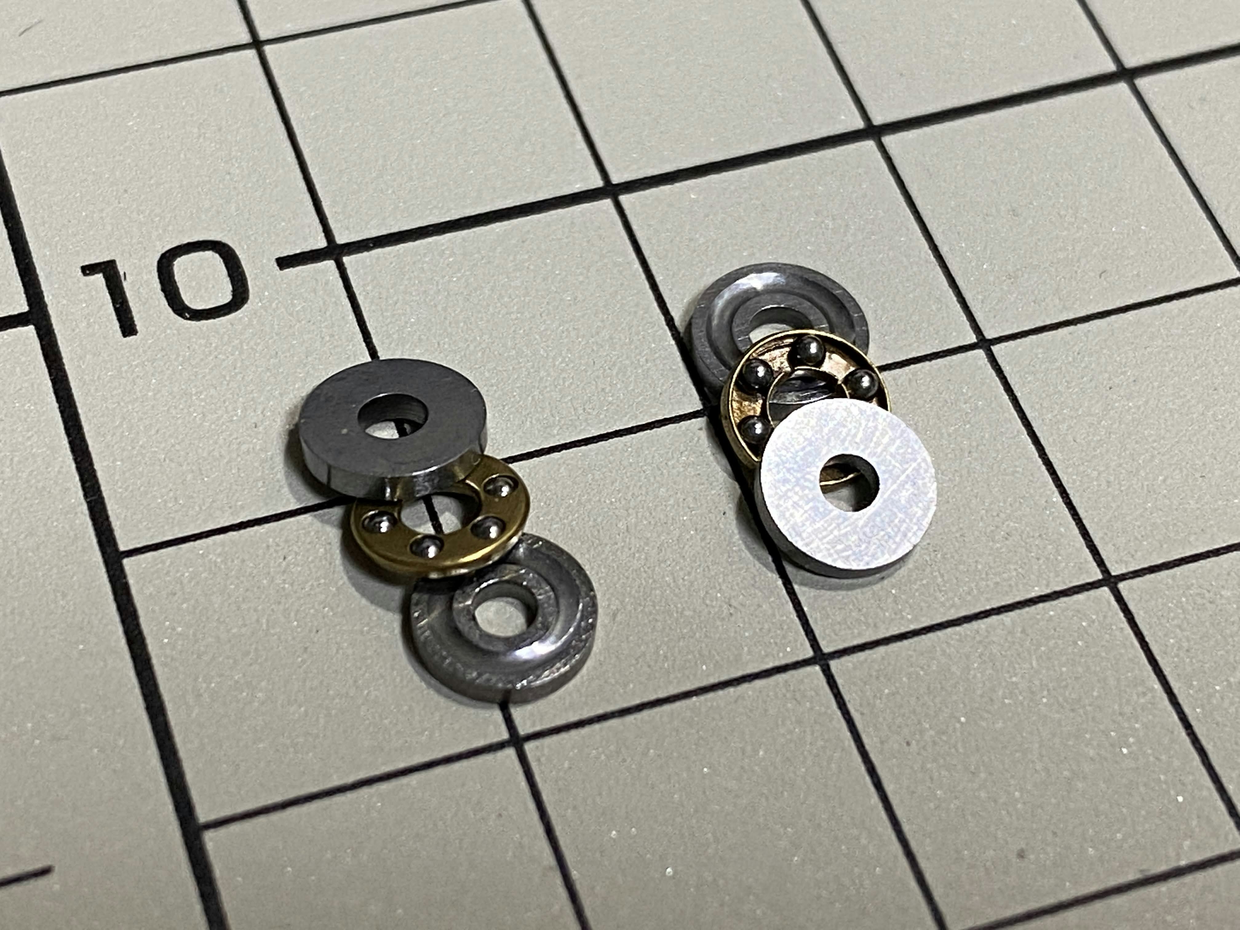
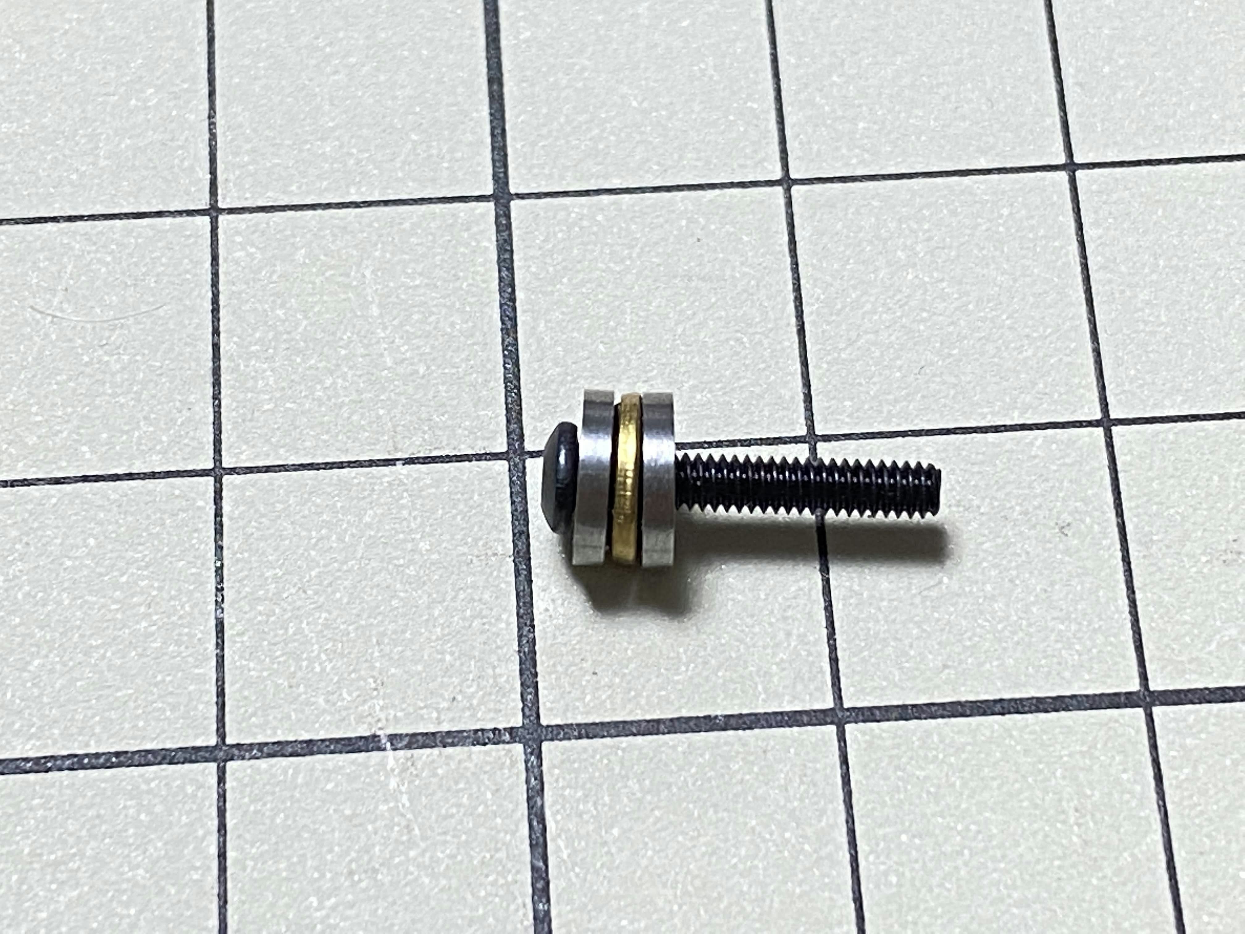
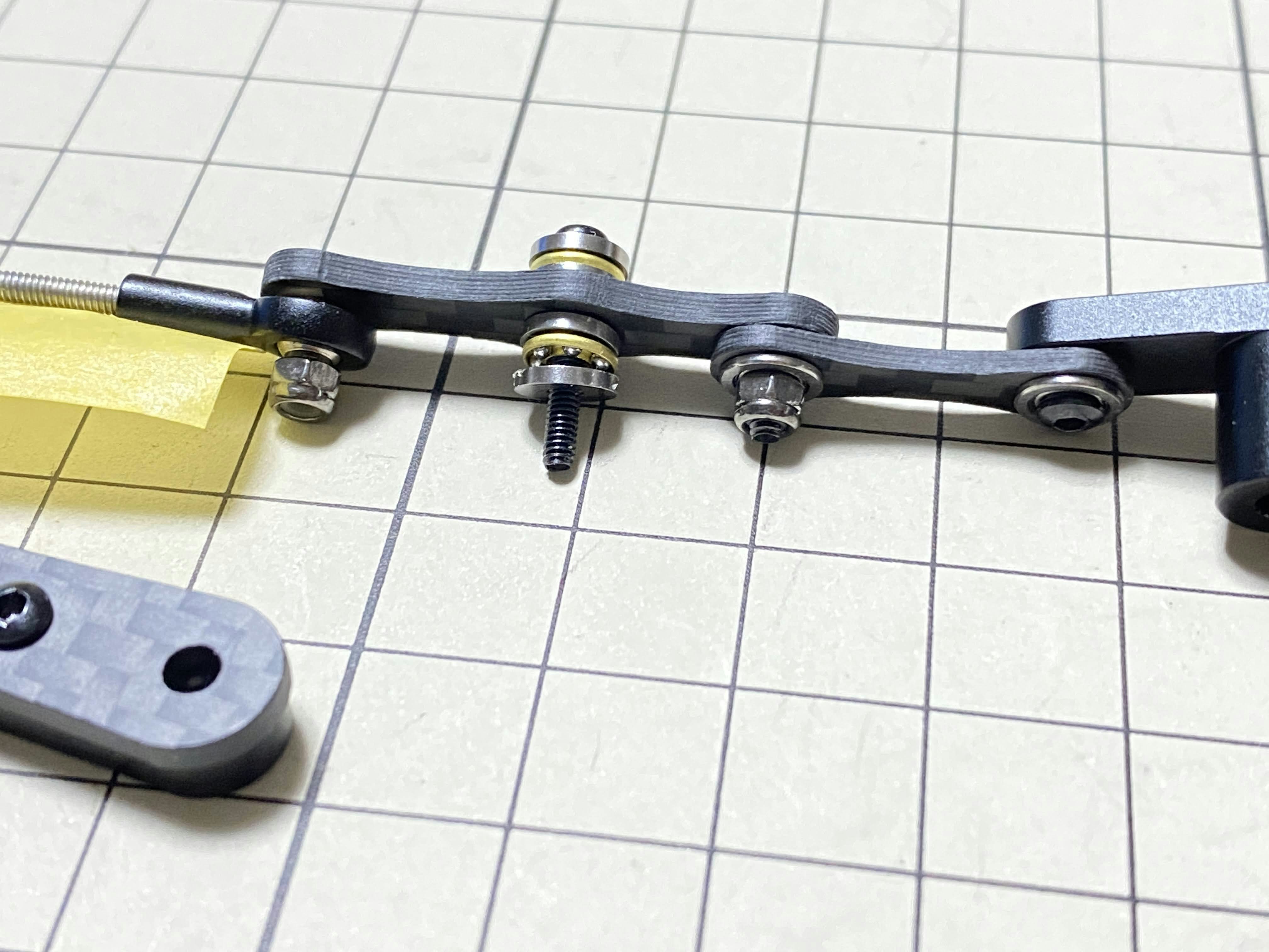
M2x12mmのボルトとM2 locknutとボールベアリング2組を使用します。ボールベアリングは3つの部品から成り立っており、上下の部品は溝がある方を内側に向けて、真ん中の部品をはさみます。まずボールベアリングにボルトを通します。次に⑦の穴にボルトを挿します。このとき⑦の反っている方向を見て、向きを間違えないように気をつけます。次にもう一つのボールベアリングをボルトに通します。最後に⑤をボルトに通してナットで締めます。
Use an M2x12mm screw, an M2 locknut and two sets of ball bearings. Each ball bearing is made up of three parts, the top and bottom parts with the grooved side facing inwards. Insert a screw into a set of ball bearing. Then insert the screw into the hole ⑦. Taking care to look at the warped side of ⑦ to make sure it is facing the right way. Now screw in the another set of ball bearing. Finally, insert screw into ⑤ and tighten it with the nut.
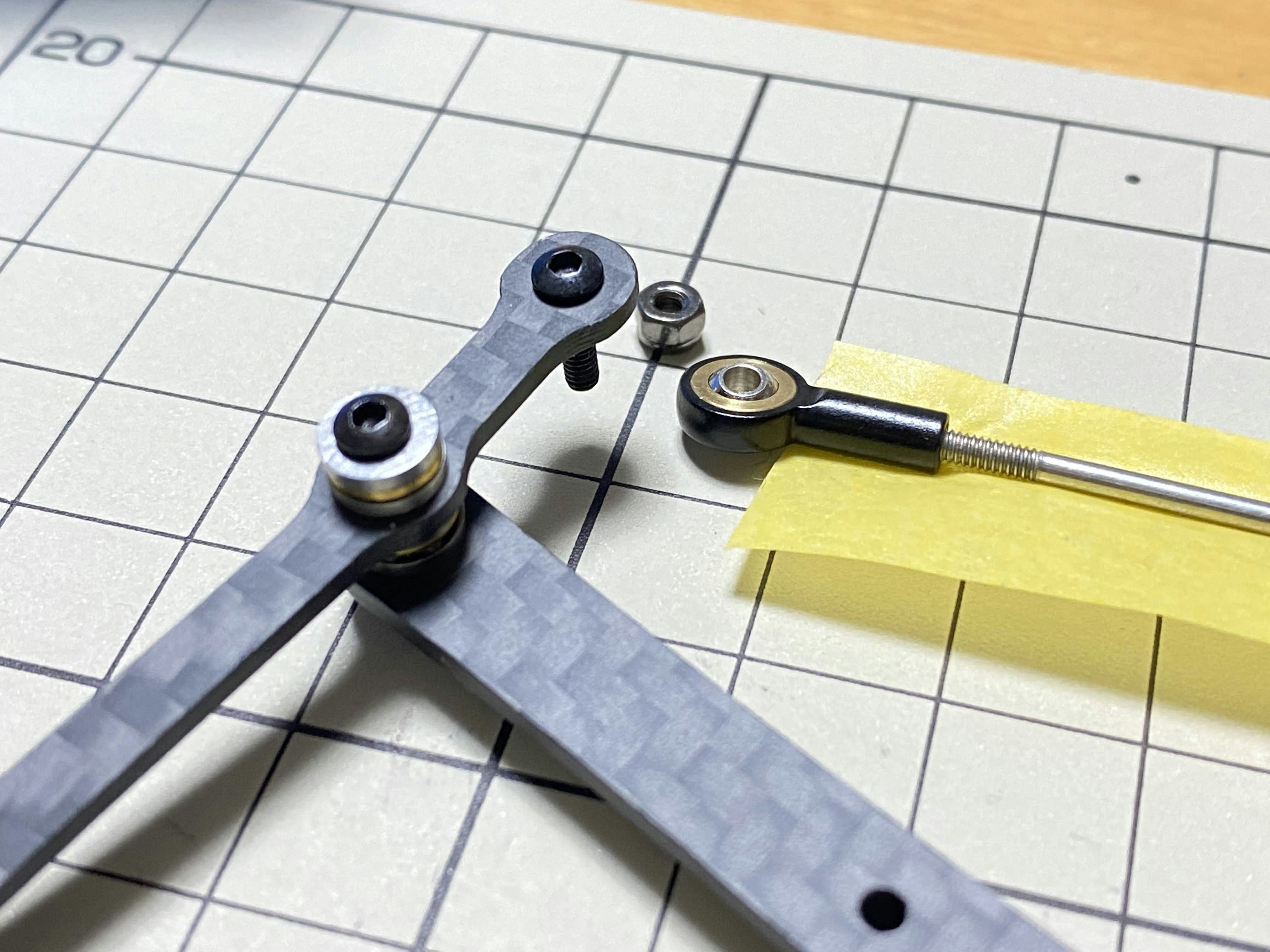
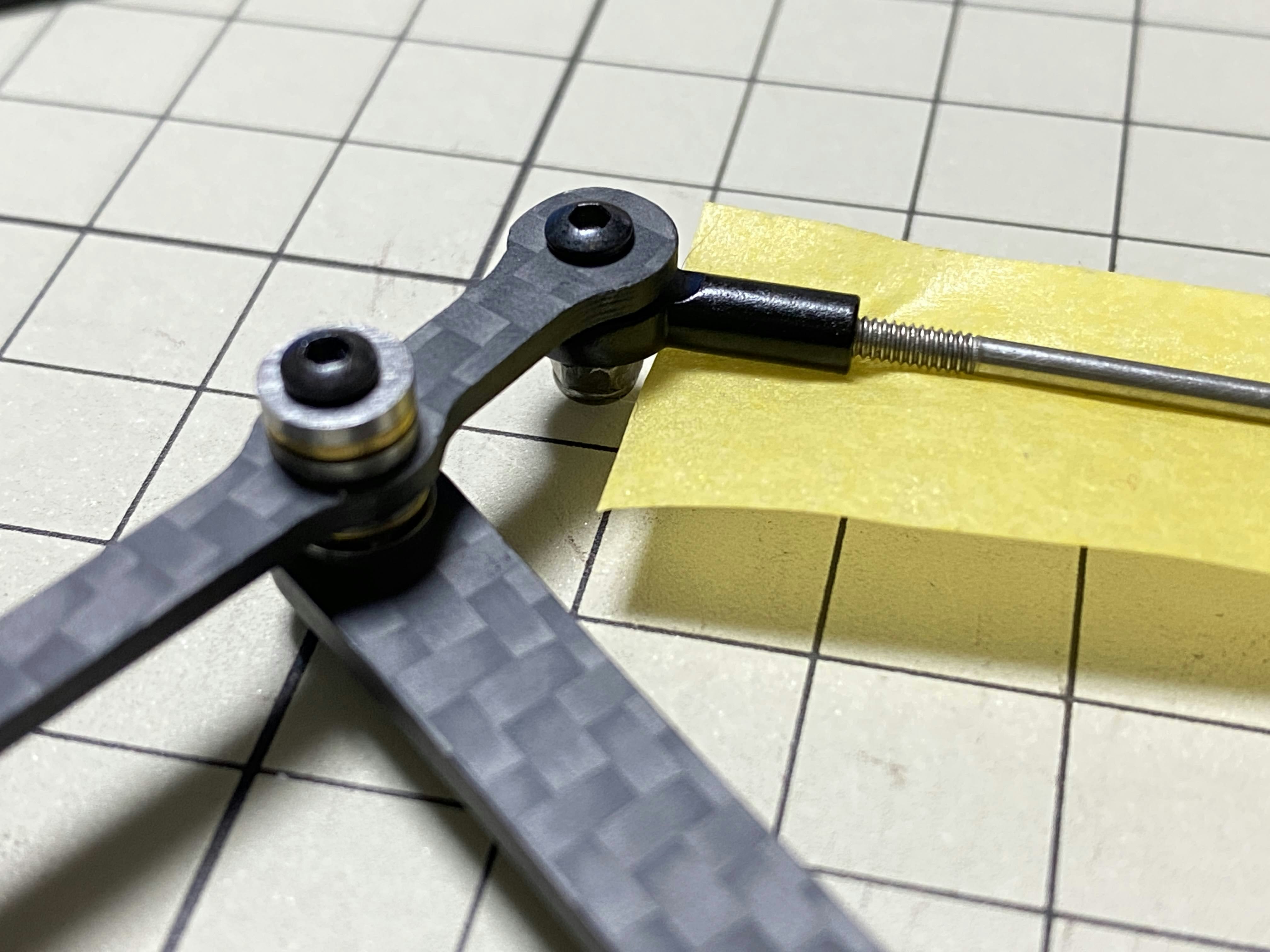
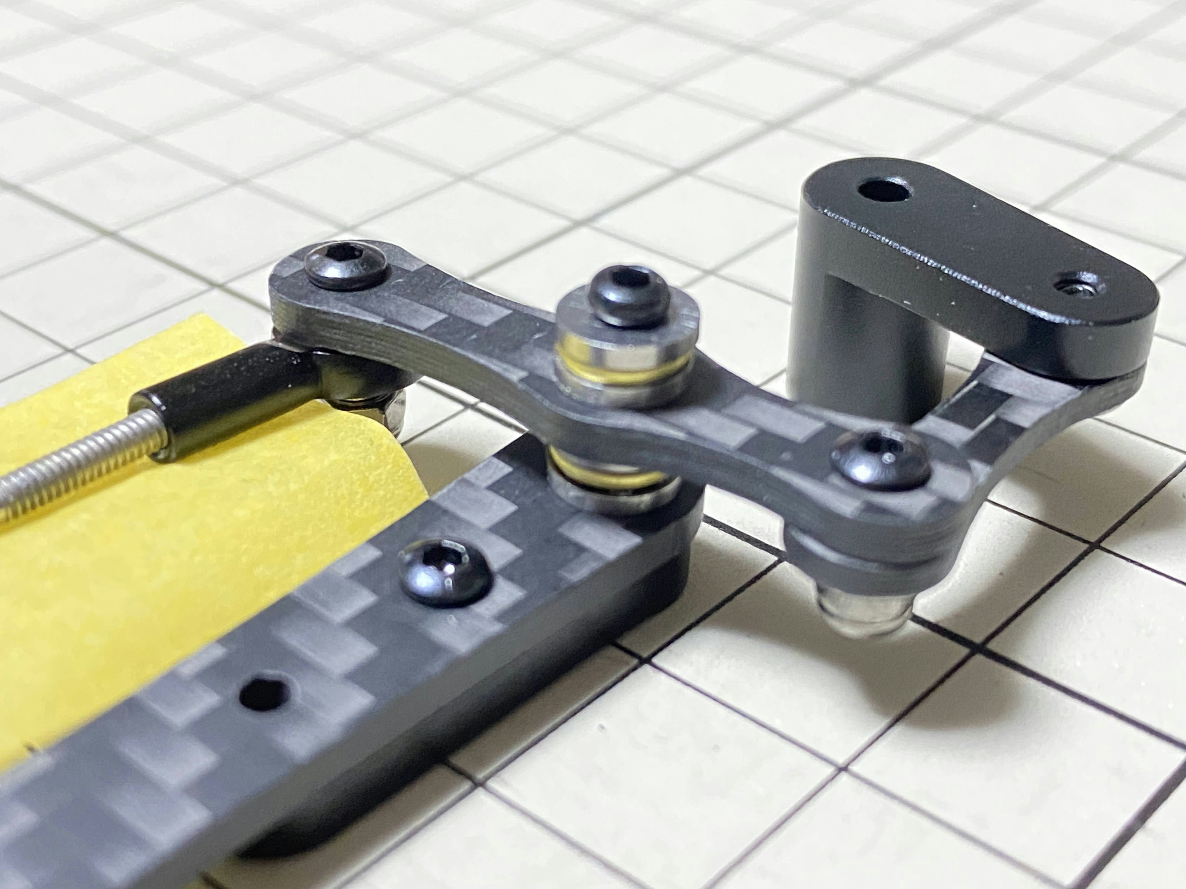
④と⑦の組み立て / Assemble ④ and ⑦
M2x8mmのボルトとM2ナットを使用します。⑦にボルトを挿し、④を通したら、ナットで締めます。④の表裏の向きはどちらでも大丈夫です。
Use an M2x8mm screw and an M2 nut. Insert the screw into ⑦ and put ④ through, then tighten it with the nut. The direction of the front and back of ④ can be either.
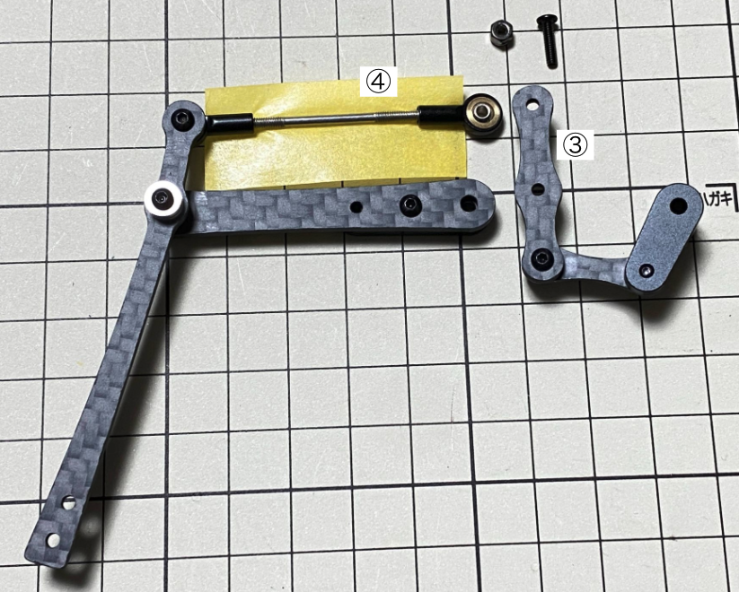
③と④の組み立て / Assemble ③ and ④
M2x8mmのボルトとM2ナットを使用します。③にボルトを挿し、④を通したら、ナットで締めます。
Use an M2x8mm screw and an M2 nut. Insert the screw into ③ and put ④ through, then tighten it with the nut.
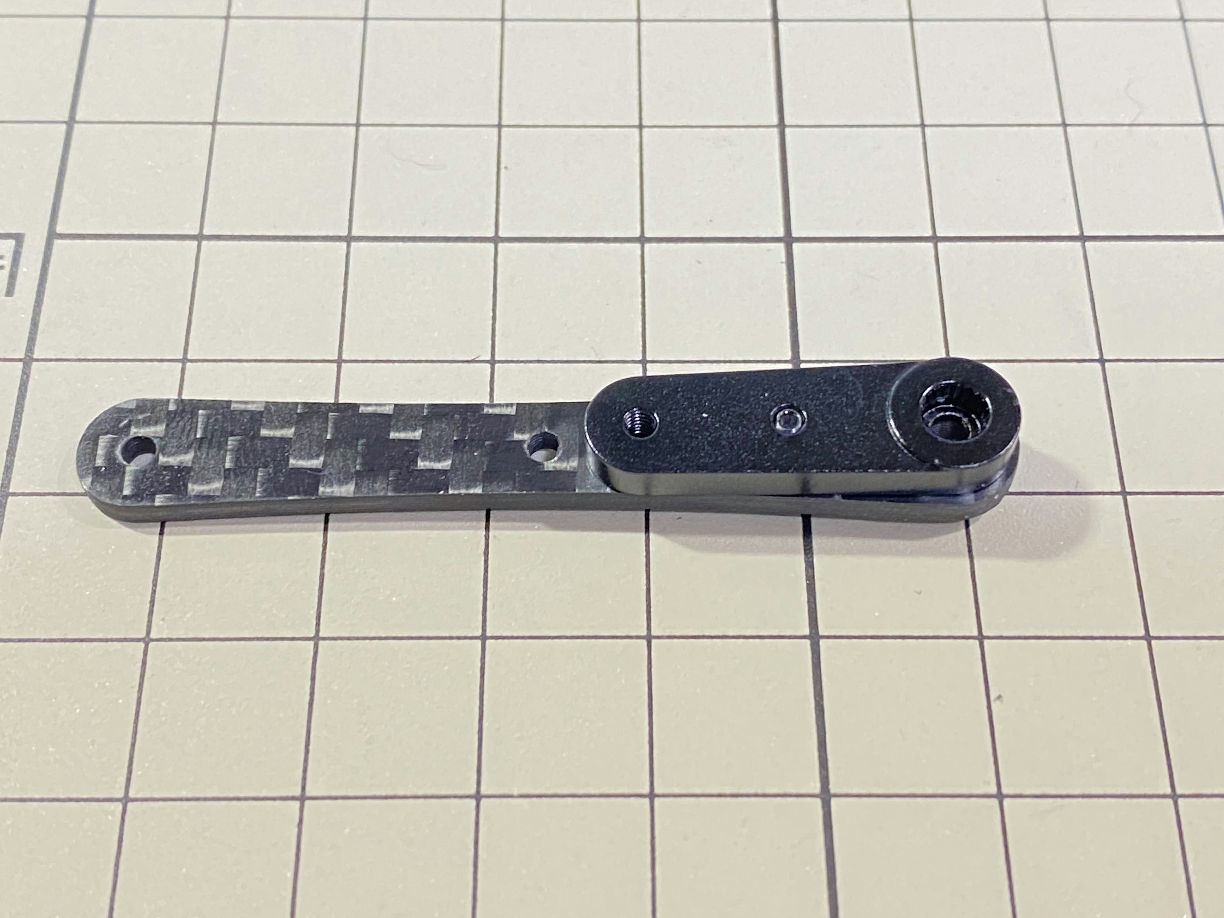
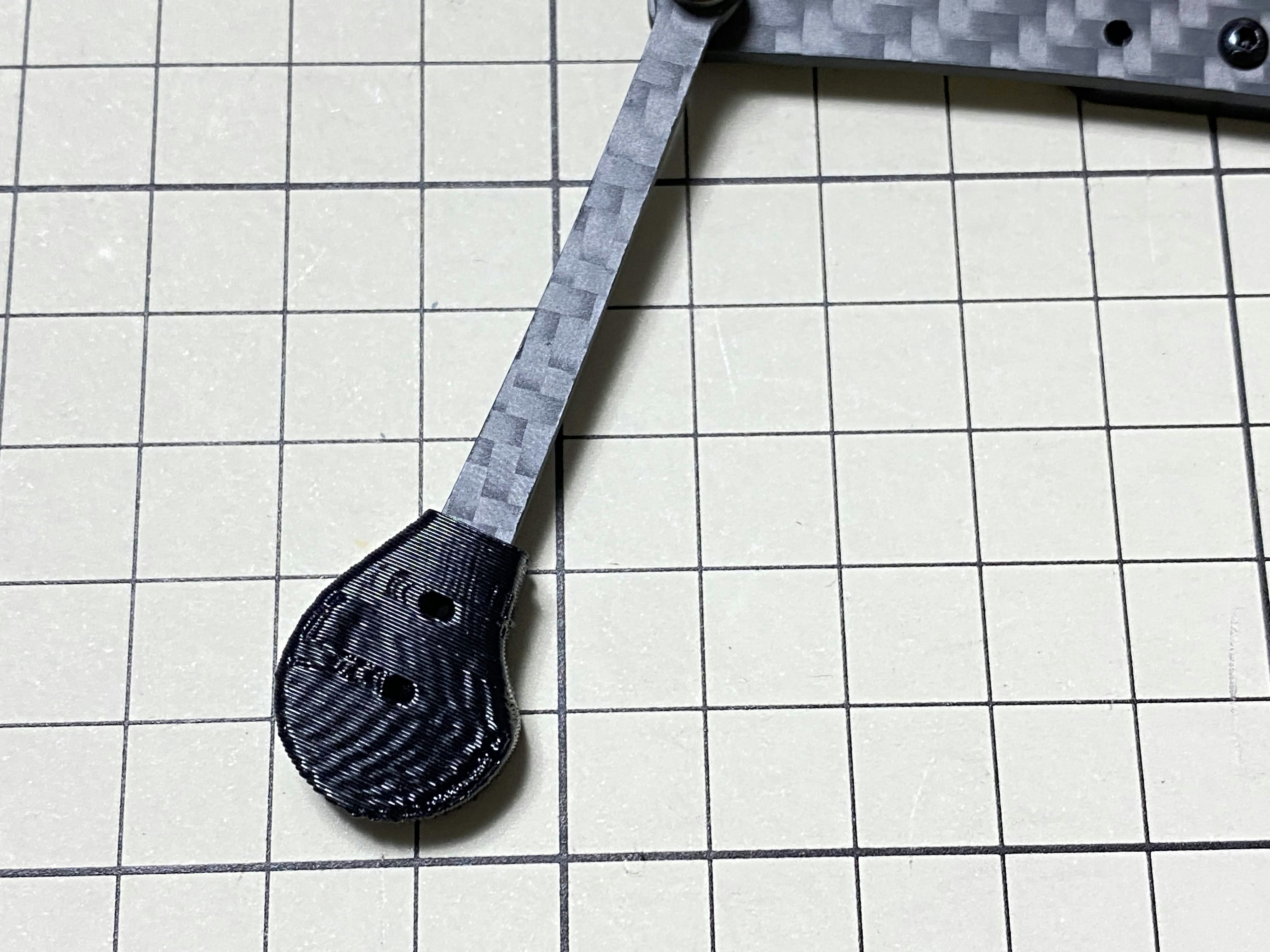
⑦と⑧の組み立て / Assemble ⑦ and ⑧
⑦の先に⑧を奥まで差し込みます。
Insert the end of ⑦ deep into the hole in ⑧.
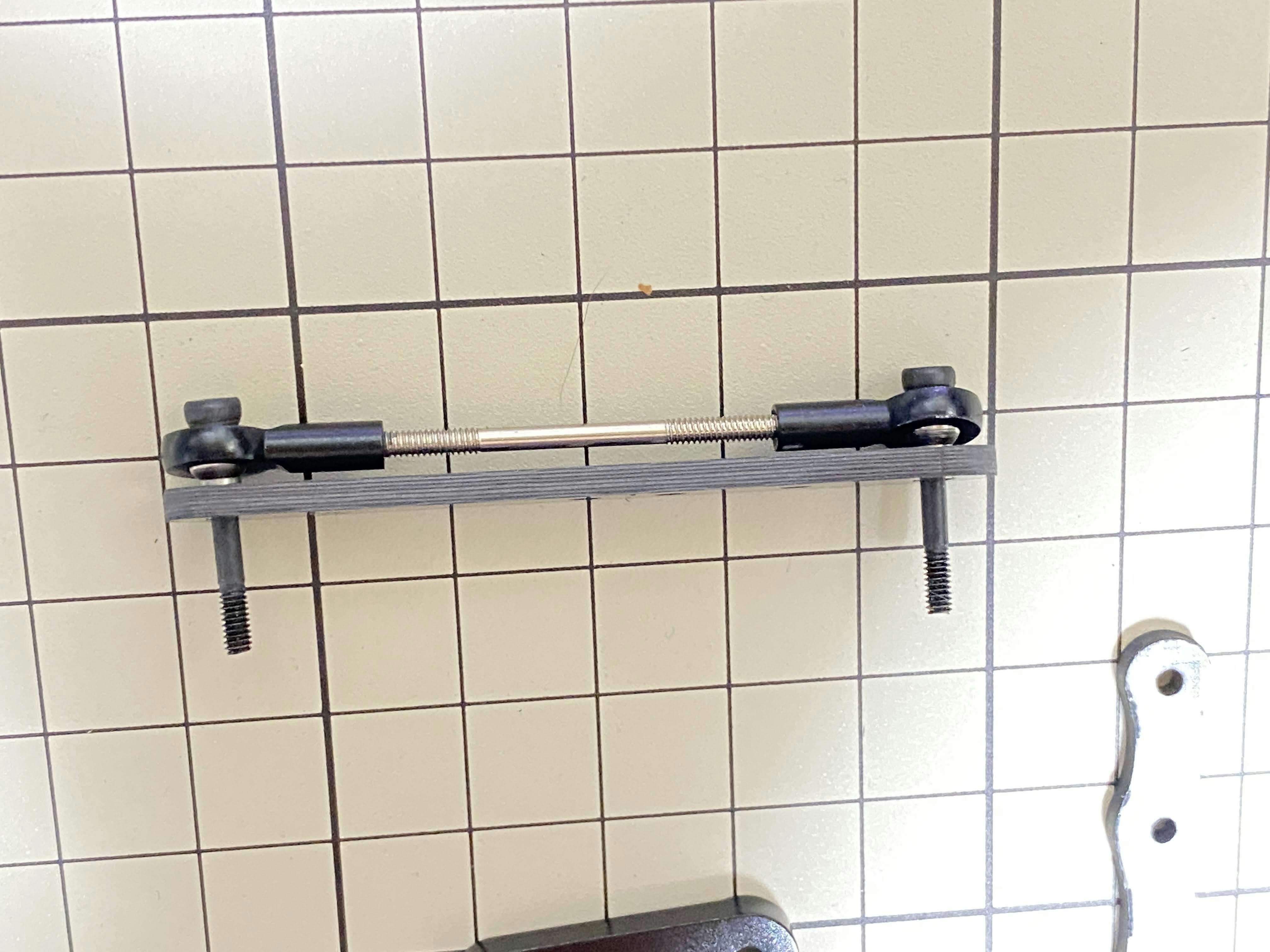
③と⑤の組み立て / Assemble ③ and ⑤
M2x14mmのボルトとボールベアリング2組を使用します。ボルトをベアリング、③、ベアリング、⑤の順で通します。ボルトは固定されていませんが、次工程でサーボに取り付ける際にボルトを締めます。
Use M2x14mm screws and two sets of ball bearings. Thread the screws through the bearings, ③, bearings, ⑤, in that order. The screws are not fixed, but you will tighten them when you mount the servo in the next step.
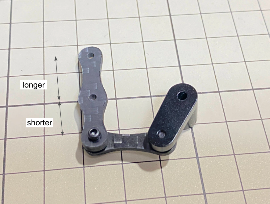
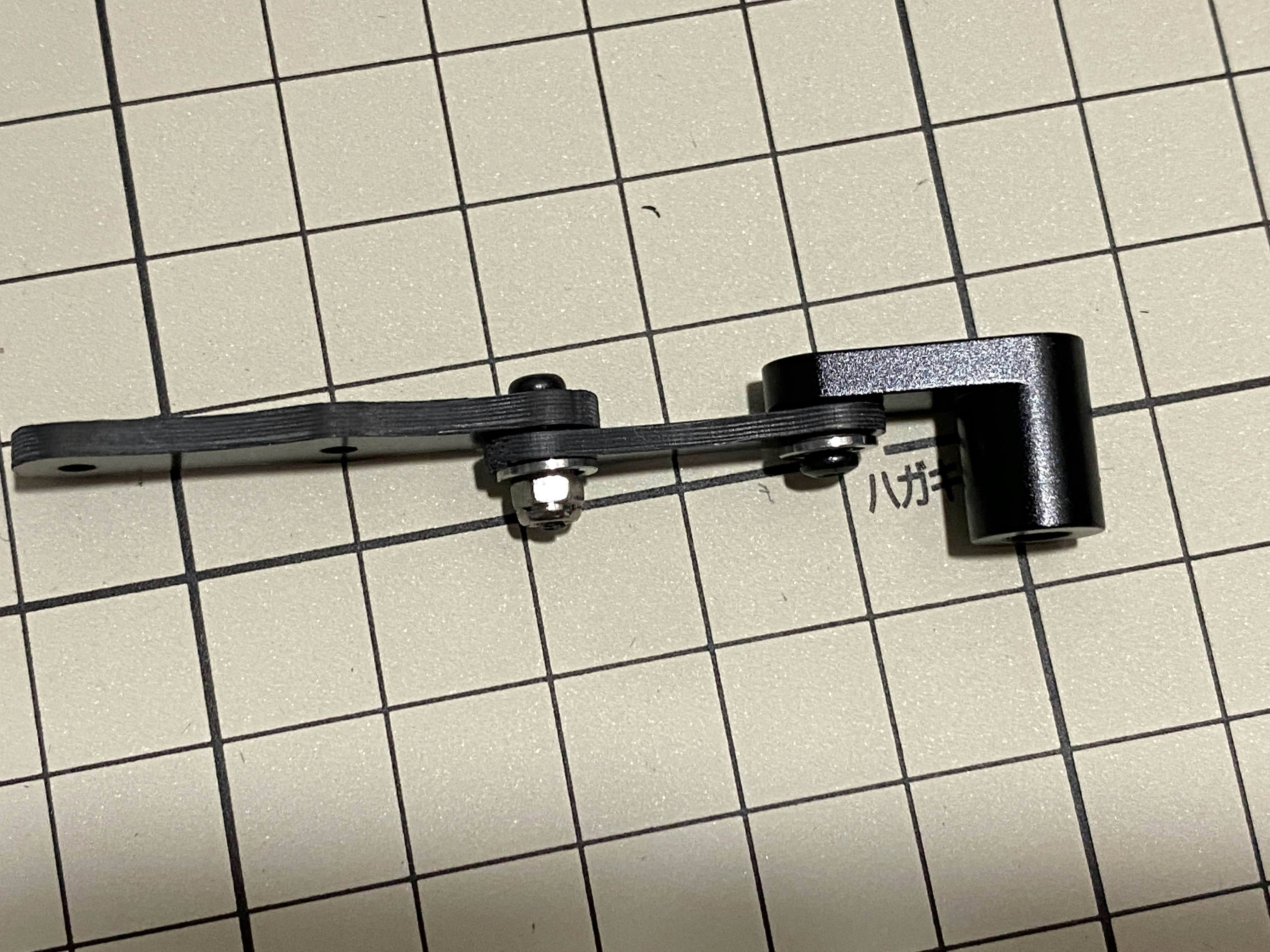
脚部の仕上げ / Completion of a right leg
表
これで右側の脚が一本完成しました。色んな角度から見れるように写真を貼っておきます。左側は右側と線対称になるように組みます。
Now we have one leg on the right side. Here are some pictures so you can see it from different angles. The left leg should be symmetrical with the right one.
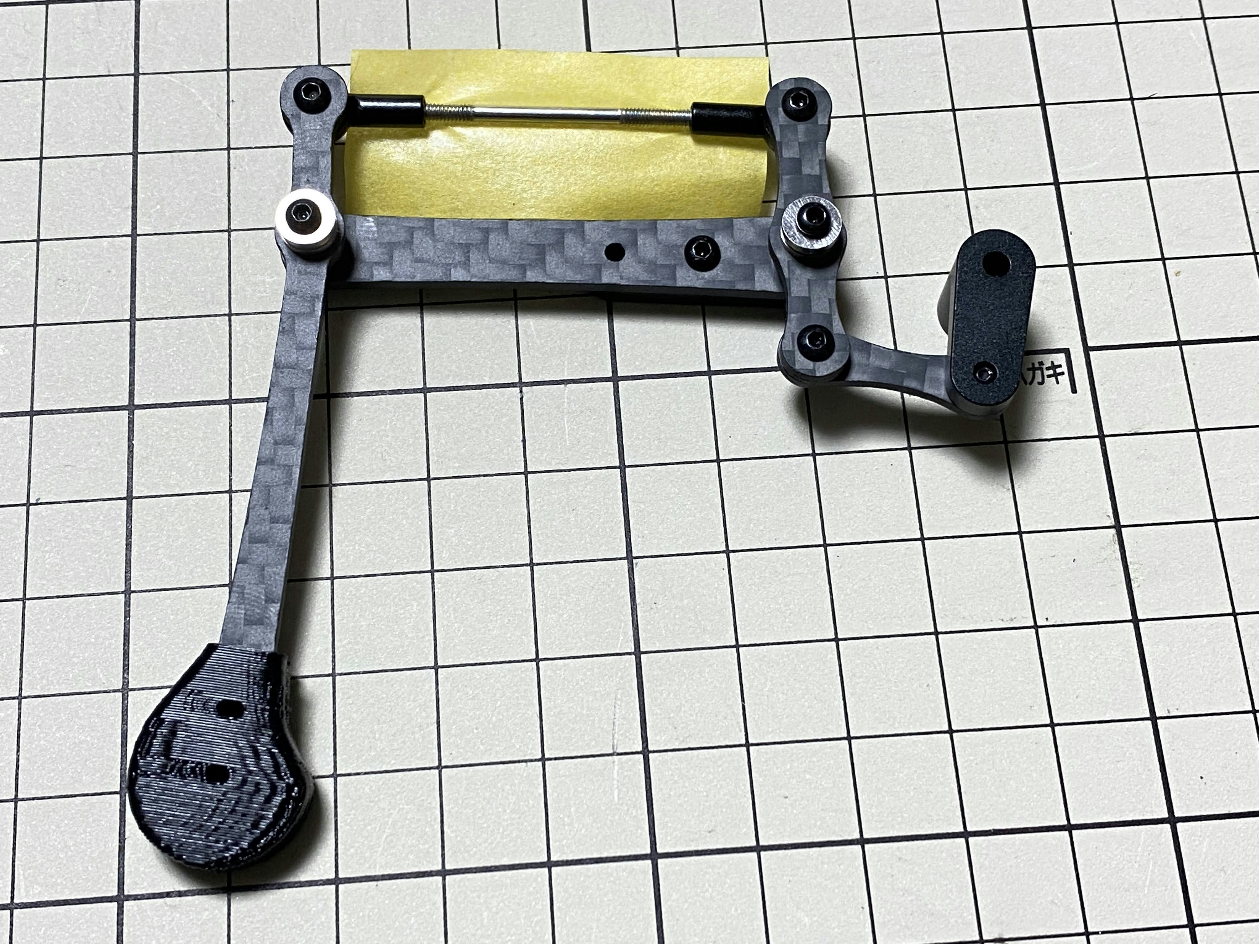
裏 / opposite side
4脚分 / Four legs
ロックタイト / Locktite
ナットは動く関節にあるので、ナットを強く締めても直ぐに緩んでしまいます。ロックタイトで固定しましょう。なお、ロックタイトで固定されたナットは強い力ならば緩められるので、あとから解体も可能です。
As the nut is on a moving joint, it will loosen quickly if tightened too tightly. They should be secured with Loctite. It is possible to dismantle the nut later, as it can be loosened by a strong force.
次工程 / next step
次は【Mini Pupper 2】臀部の組み立て方です。
Next step is on 【Mini Pupper 2】Hips Assembly.
参考 / Reference
- でべさん の 「Mini Pupper」がやってきた!(1: make 編)
- でべさんの 組み立てツイート