はじめに
これまで、Blenderスクリプトを用いてテクスチャに数値を書きこむ方法を解説しました。
Blender→Unity間で32bitテクスチャ(EXR)で数値の受け渡しを行う
では実際にこちらを用いでどんなことができるのか。
今回は各頂点の座標を書きこんで、読みだすということをやっていきます。
事前知識
VTF(Vertex Texture Fetch)
頂点テクスチャフェッチ(Vertex Texture Fetch)とは、簡単に言えば頂点シェーダー内でテクスチャを活用することです。
詳しい説明は下記サイトを読むといいです。
頂点テクスチャフェッチ(VTF)
今回は頂点シェーダー内で頂点情報テクスチャを読みこみ、その形に変形させるということをやっていきます。
ポリゴン
CGで使用されるモデルは全てポリゴンで形成されています。
さらに言うと、それらのポリゴンは全て三角形で形成することが出来ます。
つまり言い換えると、三角形ポリゴンを適切に動かせればどんなモデルでも自由に再現できるということです。(ポリゴン数の制限を考えない場合)
この理念を元に変形システムを作成します。
頂点情報
頂点情報をテクスチャに記録していくわけですが、ただの頂点座標を記録すればいいわけではありません。
モデルにおいては重複する頂点がいくつも発生してきます。
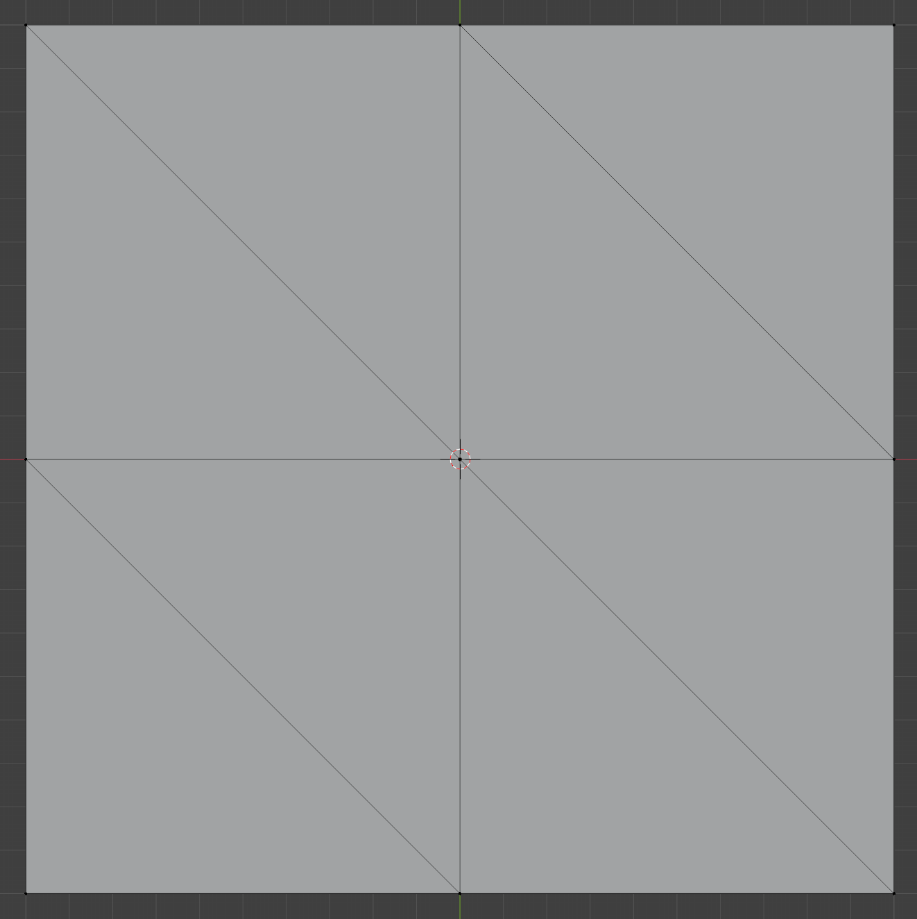
こちらの平面は8ポリゴンですが、頂点数は9個です。
先ほどの各三角形を適切に動かすという理念では、9個の頂点情報では満足に動かせません。(重複して動く箇所が存在する)
正確には各ポリゴンの各頂点の情報、つまり8×3=24個の頂点情報が必要になります。
テクスチャ参照方法
頂点情報テクスチャを参照する際、各頂点ごとに参照するピクセルを変更する必要があります。
そのような場合、UV展開することで解決できます。
Unityのシェーダーでは各頂点ごとにUV値の情報を送ることが出来ます。
頂点プログラムへ頂点データの流し込み
この値を用いることで、特定の頂点は特定のピクセル情報を読みだすということが可能です。
それでは実際にやっていきましょう。
Blender
テクスチャ作成
テクスチャクラスは前回作成したものを流用していきます。
画像形式はEXRです。
import bpy
import numpy as np

class TextureClass:
    def __init__(self, texture_name, width, height):
        self.image = bpy.data.images.get(texture_name)
        if not self.image:
            self.image = bpy.data.images.new(texture_name, width=width, height=height, alpha=True, float_buffer=True)
        elif self.image.size[0] != width or self.image.size[1] != height:
            self.image.scale(width, height)

        self.image.file_format = 'OPEN_EXR'

        self.point = np.array(self.image.pixels[:])
        self.point.resize(height, width * 4)
        self.point[:] = 0

        self.point_R = self.point[::, 0::4]
        self.point_G = self.point[::, 1::4]
        self.point_B = self.point[::, 2::4]
        self.point_A = self.point[::, 3::4]

    def SetPixel(self, py, px, r, g, b, a):
        self.point_R[py][px] = r
        self.point_G[py][px] = g
        self.point_B[py][px] = b
        self.point_A[py][px] = a

    def Export(self):
        self.image.pixels = self.point.flatten()
ポリゴンの三角形化
オブジェクトのポリゴンを全て三角形化するスクリプトを作成します。
import bpy
import numpy as np

class TextureClass:
    def __init__(self, texture_name, width, height):
        self.image = bpy.data.images.get(texture_name)
        if not self.image:
            self.image = bpy.data.images.new(texture_name, width=width, height=height, alpha=True, float_buffer=True)
        elif self.image.size[0] != width or self.image.size[1] != height:
            self.image.scale(width, height)

        self.image.file_format = 'OPEN_EXR'

        self.point = np.array(self.image.pixels[:])
        self.point.resize(height, width * 4)
        self.point[:] = 0

        self.point_R = self.point[::, 0::4]
        self.point_G = self.point[::, 1::4]
        self.point_B = self.point[::, 2::4]
        self.point_A = self.point[::, 3::4]

    def SetPixel(self, py, px, r, g, b, a):
        self.point_R[py][px] = r
        self.point_G[py][px] = g
        self.point_B[py][px] = b
        self.point_A[py][px] = a

    def Export(self):
        self.image.pixels = self.point.flatten()


+ bpy.ops.object.mode_set(mode='EDIT')
+ bpy.ops.mesh.select_all(action='SELECT')
+ # 全ポリゴンを三角形化
+ bpy.ops.mesh.quads_convert_to_tris(quad_method='BEAUTY', ngon_method='BEAUTY')
+ bpy.ops.object.mode_set(mode='OBJECT')
操作方法は分かるのにスクリプトの文言が分からない場合は、[Scripting]タブのコマンド履歴が役に立ちます。

これは実際に行った操作をスクリプトとして表示してくれます。
UV配置
それではUVを作成していきます。
UVの並べ方ですが、各ピクセルごとに各頂点を配置するような形が操作しやすそうです。
しかし、UV値はピクセル数に関係なく0~1範囲のため、そのように変換する必要があります。
以上を踏まえたプログラムが以下の通りです。
import bpy
import numpy as np

class TextureClass:
    def __init__(self, texture_name, width, height):
        self.image = bpy.data.images.get(texture_name)
        if not self.image:
            self.image = bpy.data.images.new(texture_name, width=width, height=height, alpha=True, float_buffer=True)
        elif self.image.size[0] != width or self.image.size[1] != height:
            self.image.scale(width, height)

        self.image.file_format = 'OPEN_EXR'

        self.point = np.array(self.image.pixels[:])
        self.point.resize(height, width * 4)
        self.point[:] = 0

        self.point_R = self.point[::, 0::4]
        self.point_G = self.point[::, 1::4]
        self.point_B = self.point[::, 2::4]
        self.point_A = self.point[::, 3::4]

    def SetPixel(self, py, px, r, g, b, a):
        self.point_R[py][px] = r
        self.point_G[py][px] = g
        self.point_B[py][px] = b
        self.point_A[py][px] = a

    def Export(self):
        self.image.pixels = self.point.flatten()


+ # 解像度の指定
+ resolution = 8
+ mesh = bpy.context.active_object.data

bpy.ops.object.mode_set(mode='EDIT')
bpy.ops.mesh.select_all(action='SELECT')
# 全ポリゴンを三角形化
bpy.ops.mesh.quads_convert_to_tris(quad_method='BEAUTY', ngon_method='BEAUTY')
bpy.ops.object.mode_set(mode='OBJECT')

+ uv_layer = mesh.uv_layers.get("VertexUV")
+ if not uv_layer:
+     uv_layer = mesh.uv_layers.new(name="VertexUV")
+
+ count = 0
+ for polygon in mesh.polygons:
+     for i, loop_index in enumerate(polygon.loop_indices):
+         pixel = [int(count % resolution), int(count // resolution)]
+
+         # UV再配置
+         uv_layer.data[loop_index].uv = [
+             pixel[0] / resolution + 1 / (resolution * 2),
+             pixel[1] / resolution + 1 / (resolution * 2)
+             ]
+
+         count += 1
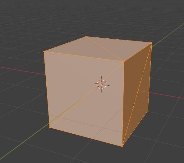
立方体に適応してみると以下のようになります。
左画面がUVマップです。
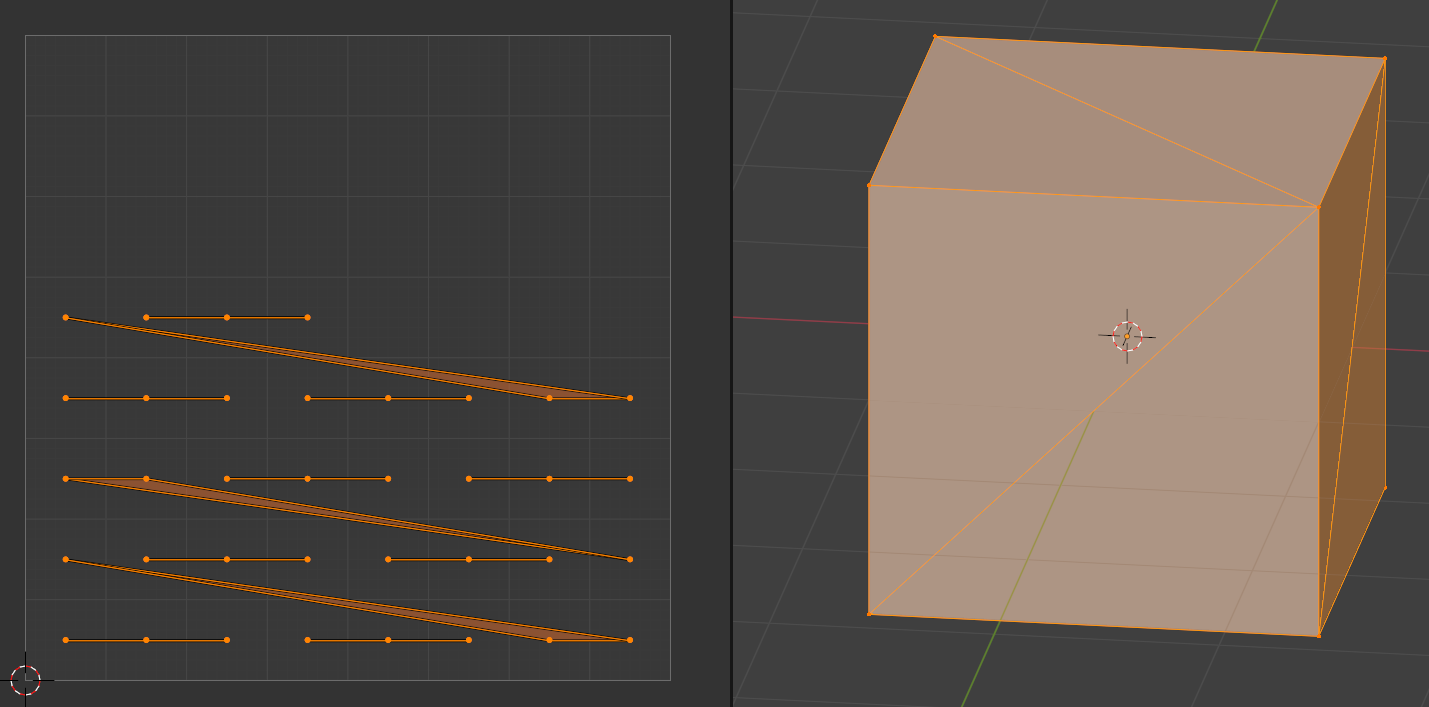
縦横等間隔に配置できています。
8ピクセルを指定してちゃんと8等分になっていますね。
それでは追加箇所を解説していきます。
UVレイヤー取得
テクスチャ用のUVと競合しないように、新しくUVレイヤーを作成、取得します。
uv_layer = mesh.uv_layers.get("VertexUV")
if not uv_layer:
    uv_layer = mesh.uv_layers.new(name="VertexUV")
全頂点の取得
count = 0
for polygon in mesh.polygons:
    for i, loop_index in enumerate(polygon.loop_indices):
        #...
        count += 1
上記の2重for文で各ポリゴンの各頂点が取得できます。
またcount変数を追加して今何頂点目かを記録しています。
ピクセルの取得
pixel = [int(count % resolution), int(count // resolution)]
増加する数値から縦横のピクセル値を取得する計算は上記で出来ます。
%(剰余演算子)は割った余りを、//は商の整数部のみを取得できます。
UV範囲に変換、適応
        # UV再配置
        uv_layer.data[loop_index].uv = [
            pixel[0] / resolution + 1 / (resolution * 2),
            pixel[1] / resolution + 1 / (resolution * 2)
            ]
ピクセル値を解像度で割ることで0~1の範囲にすることが出来ます。
また、解像度の2倍の逆数(1 / (resolution * 2))を足すことでピクセルの中心位置に移動できます。
頂点情報記録
ちょうどよく各ポリゴンの各頂点をfor文で回しているので、その情報を流用します。
頂点座標はX、Y、Zあり、それぞれ32bit floatです。
今回はそれらの情報をテクスチャのRed、Green、Blueに格納します。
また、法線情報も保存したいのですがAlphaしか空いていないので、X、Y、Zそれぞれ32bitある法線情報を全部で32bitとなるように圧縮してAlphaに格納します。
import bpy
import numpy as np
+ import struct

class TextureClass:
    def __init__(self, texture_name, width, height):
        self.image = bpy.data.images.get(texture_name)
        if not self.image:
            self.image = bpy.data.images.new(texture_name, width=width, height=height, alpha=True, float_buffer=True)
        elif self.image.size[0] != width or self.image.size[1] != height:
            self.image.scale(width, height)

        self.image.file_format = 'OPEN_EXR'

        self.point = np.array(self.image.pixels[:])
        self.point.resize(height, width * 4)
        self.point[:] = 0

        self.point_R = self.point[::, 0::4]
        self.point_G = self.point[::, 1::4]
        self.point_B = self.point[::, 2::4]
        self.point_A = self.point[::, 3::4]

    def SetPixel(self, py, px, r, g, b, a):
        self.point_R[py][px] = r
        self.point_G[py][px] = g
        self.point_B[py][px] = b
        self.point_A[py][px] = a

    def Export(self):
        self.image.pixels = self.point.flatten()


+ # Normal値をfloatにまとめる
+ def NormalToFloat(x, y, z):
+     # -1~1 -> 0~255
+     x_8bit, y_8bit, z_8bit = map(lambda v: int((v / 2 + 0.5) * 255), (x, y, z))
+     packed_24bit = (x_8bit << 16) | (y_8bit << 8) | z_8bit
+     # 24ビットの整数を32ビットの浮動小数点数に変換
+     return struct.unpack('!f', struct.pack('!I', packed_24bit))[0]


# 解像度の指定
resolution = 8
mesh = bpy.context.active_object.data

+ texture = TextureClass('Texture_' + str(resolution), resolution, resolution)

bpy.ops.object.mode_set(mode='EDIT')
bpy.ops.mesh.select_all(action='SELECT')
# 全ポリゴンを三角形化
bpy.ops.mesh.quads_convert_to_tris(quad_method='BEAUTY', ngon_method='BEAUTY')
bpy.ops.object.mode_set(mode='OBJECT')

uv_layer = mesh.uv_layers.get("VertexUV")
if not uv_layer:
    uv_layer = mesh.uv_layers.new(name="VertexUV")

count = 0
for polygon in mesh.polygons:
    for i, loop_index in enumerate(polygon.loop_indices):
        pixel = [int(count % resolution), int(count // resolution)]

        # UV再配置
        uv_layer.data[loop_index].uv = [
            pixel[0] / resolution + 1 / (resolution * 2),
            pixel[1] / resolution + 1 / (resolution * 2)
            ]

+         vertex_co = mesh.vertices[polygon.vertices[i]].co
+         normal = mesh.vertices[polygon.vertices[i]].normal.normalized()
+
+         texture.SetPixel(pixel[1], pixel[0], *vertex_co, NormalToFloat(*normal))

        count += 1

+ texture.Export()
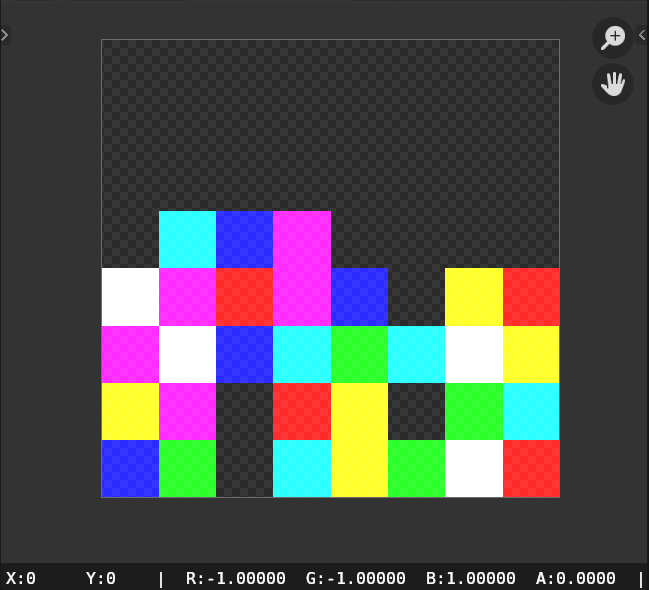
実際はAlphaが0に近いはずなので色味は異なっていますが、実行できました。
頂点座標の取得
        vertex_co = mesh.vertices[polygon.vertices[i]].co
        normal = mesh.vertices[polygon.vertices[i]].normal.normalized()

        texture.SetPixel(pixel[1], pixel[0], *vertex_co, NormalToFloat(*normal))
上記の方法で頂点座標、法線方向を取得できます。
また、32bitテクスチャなので座標をそのまま色に代入できます。
法線の圧縮
# Normal値をfloatにまとめる
def NormalToFloat(x, y, z):
    # -1~1 -> 0~255
    x_8bit, y_8bit, z_8bit = map(lambda v: int((v / 2 0.5) * 255), (x, y, z))
    packed_24bit = (x_8bit << 16) | (y_8bit << 8) | z_8bit
    # 24ビットの整数を32ビットの浮動小数点数に変換
    return struct.unpack('!f', struct.pack('!I', packed_24bit))[0]
上記の関数で法線をまとめることが出来ます。
法線は-1~1の範囲なので、まず÷2をして-0.5~0.5にし、+0.5をして0~1の範囲にします。
そして8bitに圧縮するため255を掛けて整数型に丸めます。
それらを繋げて32bit floatにします。
スクリプト全文
最終的には以下のようなスクリプトになりました。
import bpy
import numpy as np
import struct

class TextureClass:
    def __init__(self, texture_name, width, height):
        self.image = bpy.data.images.get(texture_name)
        if not self.image:
            self.image = bpy.data.images.new(texture_name, width=width, height=height, alpha=True, float_buffer=True)
        elif self.image.size[0] != width or self.image.size[1] != height:
            self.image.scale(width, height)

        self.image.file_format = 'OPEN_EXR'

        self.point = np.array(self.image.pixels[:])
        self.point.resize(height, width * 4)
        self.point[:] = 0

        self.point_R = self.point[::, 0::4]
        self.point_G = self.point[::, 1::4]
        self.point_B = self.point[::, 2::4]
        self.point_A = self.point[::, 3::4]

    def SetPixel(self, py, px, r, g, b, a):
        self.point_R[py][px] = r
        self.point_G[py][px] = g
        self.point_B[py][px] = b
        self.point_A[py][px] = a

    def Export(self):
        self.image.pixels = self.point.flatten()


# Normal値をfloatにまとめる
def NormalToFloat(x, y, z):
    # -1~1 -> 0~255
    x_8bit, y_8bit, z_8bit = map(lambda v: int((v / 2 + 0.5) * 255), (x, y, z))
    packed_24bit = (x_8bit << 16) | (y_8bit << 8) | z_8bit
    # 24ビットの整数を32ビットの浮動小数点数に変換
    return struct.unpack('!f', struct.pack('!I', packed_24bit))[0]


# 解像度の指定
resolution = 8
mesh = bpy.context.active_object.data

texture = TextureClass('Texture_' + str(resolution), resolution, resolution)

bpy.ops.object.mode_set(mode='EDIT')
bpy.ops.mesh.select_all(action='SELECT')
# 全ポリゴンを三角形化
bpy.ops.mesh.quads_convert_to_tris(quad_method='BEAUTY', ngon_method='BEAUTY')
bpy.ops.object.mode_set(mode='OBJECT')

uv_layer = mesh.uv_layers.get("VertexUV")
if not uv_layer:
    uv_layer = mesh.uv_layers.new(name="VertexUV")

count = 0
for polygon in mesh.polygons:
    for i, loop_index in enumerate(polygon.loop_indices):
        pixel = [int(count % resolution), int(count // resolution)]

        # UV再配置
        uv_layer.data[loop_index].uv = [
            pixel[0] / resolution + 1 / (resolution * 2),
            pixel[1] / resolution + 1 / (resolution * 2)
            ]

        vertex_co = mesh.vertices[polygon.vertices[i]].co
        normal = mesh.vertices[polygon.vertices[i]].normal.normalized()

        texture.SetPixel(pixel[1], pixel[0], *vertex_co, NormalToFloat(*normal))

        count += 1

texture.Export()
Unity
改変元プログラム
以下のランバートシェーダーを基本として拡張していきます。
Shader "nekoya/VTF"
{
    Properties
    {
        _MainTex ("Texture", 2D) = "white" {}
    }
    SubShader
    {
        Tags { "RenderType"="Opaque" "LightMode" = "ForwardBase" }
        LOD 100

        Pass
        {
            CGPROGRAM
            #pragma vertex vert
            #pragma fragment frag

            #include "UnityCG.cginc"

            struct appdata
            {
                float4 vertex : POSITION;
                float3 normal : NORMAL;
                float2 uv : TEXCOORD0;
            };

            struct v2f
            {
                float4 vertex : SV_POSITION;
                float2 uv : TEXCOORD0;
                half3 normal : TEXCOORD1;
            };

            sampler2D _MainTex;
            float4 _MainTex_ST;
            fixed4 _LightColor0;

            v2f vert (appdata v)
            {
                v2f o;
                o.vertex = UnityObjectToClipPos(v.vertex);
                o.normal = UnityObjectToWorldNormal(v.normal);
                o.uv = TRANSFORM_TEX(v.uv, _MainTex);
                return o;
            }

            fixed4 frag (v2f i) : SV_Target
            {
                fixed4 col = tex2D(_MainTex, i.uv);
                col.rgb *= clamp(dot(i.normal, _WorldSpaceLightPos0), .2f, .98f) * _LightColor0;
                return col;
            }
            ENDCG
        }
    }
}
改変後プログラム
VTFに対応させたシェーダーは以下の通りです。
Shader "nekoya/VTF"
{
    Properties
    {
+         _Resolution("Resolution", Float) = 1024
+         _Texture("Texture", 2D) = "white" {}
        _MainTex ("Texture", 2D) = "white" {}
    }
    SubShader
    {
        Tags { "RenderType"="Opaque" "LightMode" = "ForwardBase" }
        LOD 100

        Pass
        {
            CGPROGRAM
            #pragma vertex vert
            #pragma fragment frag

            #include "UnityCG.cginc"

            struct appdata
            {
                float4 vertex : POSITION;
-                 float3 normal : NORMAL;
                float2 uv : TEXCOORD0;
+                 float2 VertexUV : TEXCOORD1;

            };

            struct v2f
            {
                float4 vertex : SV_POSITION;
                float2 uv : TEXCOORD0;
                half3 normal : TEXCOORD1;
            };

-             sampler2D _MainTex;
+             sampler2D _Texture, _MainTex;
            float4 _MainTex_ST;
            fixed4 _LightColor0;
+             float _Resolution;

+             half3 NormalUnpack(float v){
+                 uint ix = asuint(v);
+                 half3 normal = half3((ix & 0x00FF0000) >> 16, (ix & 0x0000FF00) >> 8, ix & 0x000000FF);
+                 // 0~255 -> -1~1
+                 return (((normal / 255.0f) - 0.5f) * 2.0f);
+             }

            v2f vert (appdata v)
            {
                v2f o;
+                 float4 tex = tex2Dlod(_Texture, float4(v.VertexUV, 0, 0));
+
+                 o.vertex = float4(tex.r, tex.b, tex.g, v.vertex.w);
-                 o.vertex = UnityObjectToClipPos(v.vertex);
+                 o.vertex = UnityObjectToClipPos(o.vertex);

+                 o.normal = NormalUnpack(tex.a);
+                 o.normal = normalize(half3(o.normal.x, o.normal.z, o.normal.y));
-                 o.normal = UnityObjectToWorldNormal(v.normal);
+                 o.normal = UnityObjectToWorldNormal(o.normal);

                o.uv = TRANSFORM_TEX(v.uv, _MainTex);
                return o;
            }

            fixed4 frag (v2f i) : SV_Target
            {
                fixed4 col = tex2D(_MainTex, i.uv);
                col.rgb *= clamp(dot(i.normal, _WorldSpaceLightPos0), .2f, .98f) * _LightColor0;
                return col;
            }
            ENDCG
        }
    }
}
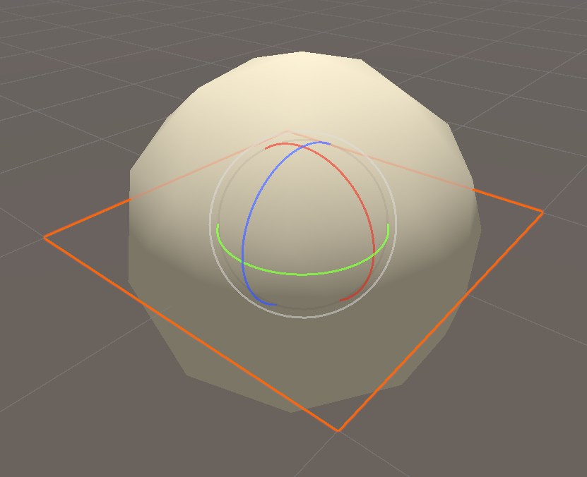
各種パラメータを設定すれば、平面モデルがICO球に変形しました。(使い方は後述します)
プログラムではパラメータの追加、UV2の追加、頂点座標・法線の変換適応などを追加しました。
テクスチャ読みこみ・数値適応
                float4 tex = tex2Dlod(_Texture, float4(v.VertexUV, 0, 0));

                o.vertex = float4(tex.r, tex.b, tex.g, v.vertex.w);
                o.vertex = UnityObjectToClipPos(o.vertex);

                o.normal = NormalUnpack(tex.a);
                o.normal = normalize(half3(o.normal.x, o.normal.z, o.normal.y));
                o.normal = UnityObjectToWorldNormal(o.normal);
テクスチャはUV2であるVertexUVを用いて読みだします。
また、BlenderとUnityは座標軸が異なるためZ軸とY軸を入れ替える必要があります。
その後適切に座標変換します。
法線情報解凍
            half3 NormalUnpack(float v){
                uint ix = asuint(v);
                half3 normal = half3((ix & 0x00FF0000) >> 16, (ix & 0x0000FF00) >> 8, ix & 0x000000FF);
                // 0~255 -> -1~1
                return (((normal / 255.0f) - 0.5f) * 2.0f);
            }
Blenderにて圧縮した工程と逆のことを行います。
32bitを8bit 3つに分けます。
その後、÷255をして0~1、-0.5をして-0.5~0.5、×2をして-1~1に復元。
シェーダー全文
シェーダ全文は以下の通りです。
Shader "nekoya/SHA_VTF"
{
    Properties
    {
        _Resolution("Resolution", Float) = 1024
        _Texture("Texture", 2D) = "white" {}
        _MainTex ("Texture", 2D) = "white" {}
    }
    SubShader
    {
        Tags { "RenderType"="Opaque" "LightMode" = "ForwardBase" }
        LOD 100

        Pass
        {
            CGPROGRAM
            #pragma vertex vert
            #pragma fragment frag

            #include "UnityCG.cginc"

            struct appdata
            {
                float4 vertex : POSITION;
                float2 uv : TEXCOORD0;
                float2 VertexUV : TEXCOORD1;
            };

            struct v2f
            {
                float4 vertex : SV_POSITION;
                float2 uv : TEXCOORD0;
                half3 normal : TEXCOORD1;
            };

            sampler2D _Texture, _MainTex;
            float4 _MainTex_ST;
            fixed4 _LightColor0;
            float _Resolution;

            half3 NormalUnpack(float v){
                uint ix = asuint(v);
                half3 normal = half3((ix & 0x00FF0000) >> 16, (ix & 0x0000FF00) >> 8, ix & 0x000000FF);
                // 0~255 -> -1~1
                return (((normal / 255.0f) - 0.5f) * 2.0f);
            }

            v2f vert (appdata v)
            {
                v2f o;
                float4 tex = tex2Dlod(_Texture, float4(v.VertexUV, 0, 0));

                o.vertex = float4(tex.r, tex.b, tex.g, v.vertex.w);
                o.vertex = UnityObjectToClipPos(o.vertex);

                o.normal = NormalUnpack(tex.a);
                o.normal = normalize(half3(o.normal.x, o.normal.z, o.normal.y));
                o.normal = UnityObjectToWorldNormal(o.normal);

                o.uv = TRANSFORM_TEX(v.uv, _MainTex);
                return o;
            }

            fixed4 frag (v2f i) : SV_Target
            {
                fixed4 col = tex2D(_MainTex, i.uv);
                col.rgb *= clamp(dot(i.normal, _WorldSpaceLightPos0), .2f, .98f) * _LightColor0;
                return col;
            }
            ENDCG
        }
    }
}
使用方法
1.頂点テクスチャ作成
まずBlenderにて変形させたい形のオブジェクトを選択して、スクリプトを実行します。
今回はICO球にしました。
また、こちらの頂点数は80ポリゴン×3=240なので、ピクセル数が240以上となるように解像度を変更します。
(今回は32にしました)
テクスチャが出力出来たら保存します。
保存形式は以前の記事に書いた通りです。
| 項目 | 値 |
|---|---|
| ファイルフォーマット | OpenEXR |
| カラー | RGBA |
| 色深度 | Float(Full) |
| コーデック | なし |
| 色空間 | 非カラー |
2.変形元オブジェクトの作成
続いて変形させる元となるオブジェクトを作成します。
今回は80ポリゴンなので、それ以上のポリゴン数を持つオブジェクトを作成し、スクリプトを実行します。
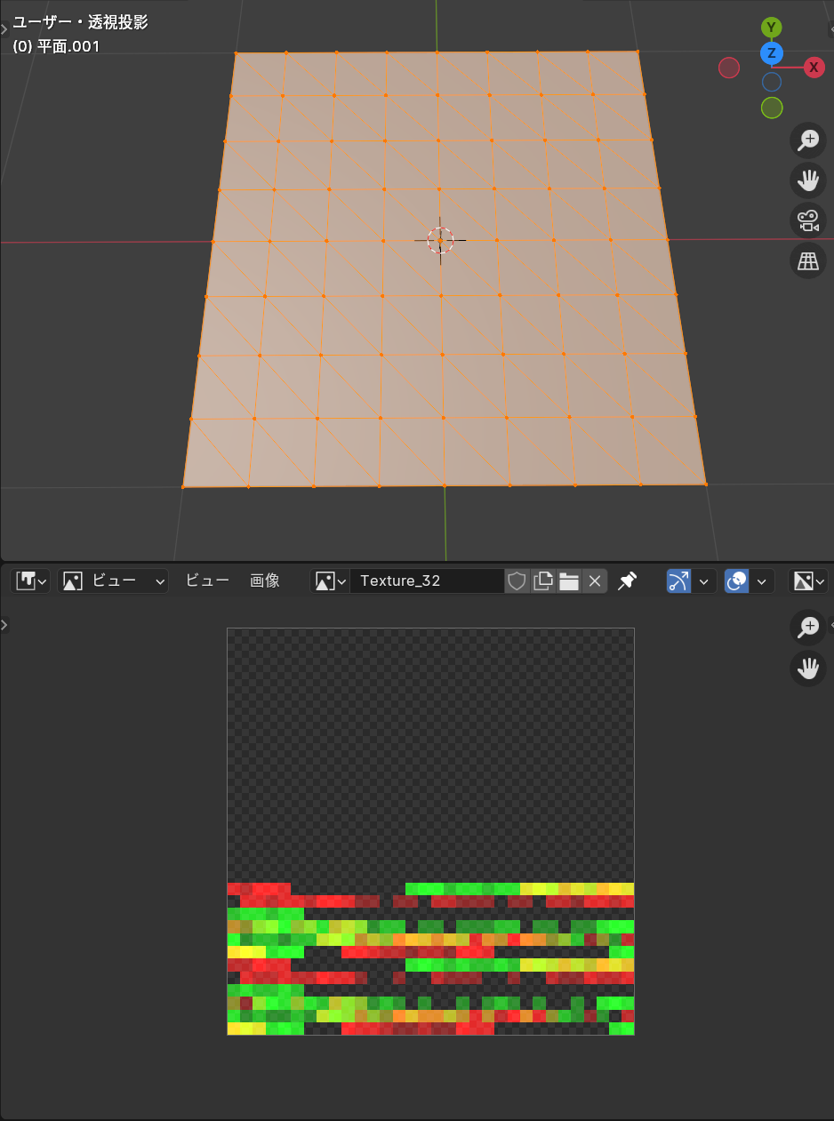
今回は128ポリゴンの平面を作成しました。
なおこちらのテクスチャは保存しなくて大丈夫です。
(三角ポリゴン化、UVを編集する目的で実行しました)
実行出来たらこちらのオブジェクトをFBXで出力します。
3.Unityにインポート
テクスチャ、FBXをUnityにインポートして設定します。
テクスチャのインポート設定は以下の通りです。
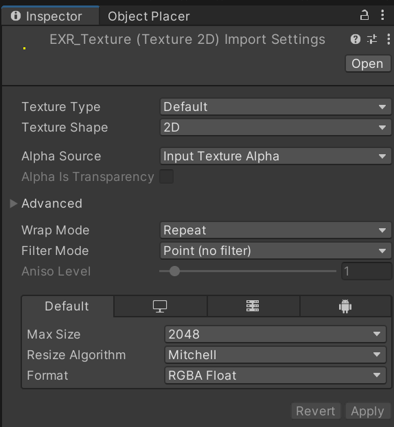
Filter Mode:Point (no filter)
Format:RGBA Float
また、プロジェクトの色空間設定はLinerに設定しておいてください。
4.マテリアル設定、適応
マテリアルの設定は以下の通りです。
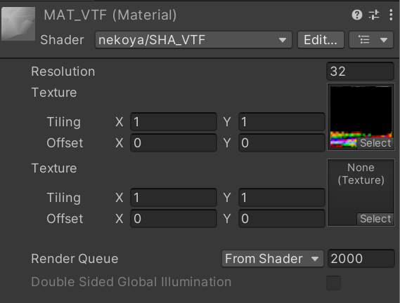
Resolution:32
Texture:インポートしたテクスチャ
マテリアルを適応して完成です。
オブジェクトの推移変形
オブジェクトAからオブジェクトBへ推移変形するようなシェーダーを作成します。
Shader "nekoya/SHA_VTF_Lerp"
{
    Properties
    {
        _Resolution("Resolution", Float) = 1024
        _Texture1("Texture1", 2D) = "white" {}
        _Texture2("Texture2", 2D) = "white" {}
        _Motion("Motion", Range(0, 1)) = 0
        _MainTex ("Texture", 2D) = "white" {}
    }
    SubShader
    {
        Tags { "RenderType"="Opaque" "LightMode" = "ForwardBase" }
        LOD 100

        Pass
        {
            CGPROGRAM
            #pragma vertex vert
            #pragma fragment frag

            #include "UnityCG.cginc"

            struct appdata
            {
                float4 vertex : POSITION;
                float2 uv : TEXCOORD0;
                float2 VertexUV : TEXCOORD1;
            };

            struct v2f
            {
                float4 vertex : SV_POSITION;
                float2 uv : TEXCOORD0;
                half3 normal : TEXCOORD1;
            };

            sampler2D _Texture1, _Texture2, _MainTex;
            float4 _MainTex_ST;
            fixed4 _LightColor0;
            float _Resolution, _Motion;

            half3 NormalUnpack(float v){
                uint ix = asuint(v);
                half3 normal = half3((ix & 0x00FF0000) >> 16, (ix & 0x0000FF00) >> 8, ix & 0x000000FF);
                // 0~255 -> -1~1
                return (((normal / 255.0f) - 0.5f) * 2.0f);
            }

            v2f vert (appdata v)
            {
                v2f o;
                float4 tex1 = tex2Dlod(_Texture1, float4(v.VertexUV, 0, 0));
                float4 tex2 = tex2Dlod(_Texture2, float4(v.VertexUV, 0, 0));

                float4 pos1 = float4(tex1.r, tex1.b, tex1.g, v.vertex.w);
                float4 pos2 = float4(tex2.r, tex2.b, tex2.g, v.vertex.w);
                o.vertex = lerp(pos1, pos2, _Motion);
                o.vertex = UnityObjectToClipPos(o.vertex);

                half3 normal1 = NormalUnpack(tex1.a);
                normal1 = normalize(half3(normal1.x, normal1.z, normal1.y));
                half3 normal2 = NormalUnpack(tex2.a);
                normal2 = normalize(half3(normal2.x, normal2.z, normal2.y));
                o.normal = lerp(normal1, normal2, _Motion);
                o.normal = UnityObjectToWorldNormal(o.normal);

                o.uv = TRANSFORM_TEX(v.uv, _MainTex);
                return o;
            }

            fixed4 frag (v2f i) : SV_Target
            {
                fixed4 col = tex2D(_MainTex, i.uv);
                col.rgb *= clamp(dot(i.normal, _WorldSpaceLightPos0), .2f, .98f) * _LightColor0;
                return col;
            }
            ENDCG
        }
    }
}
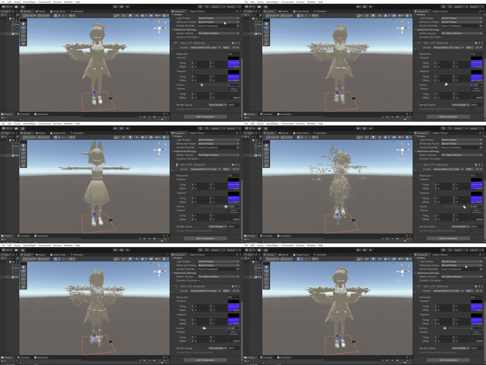
ちょっと豪勢に数万ポリゴンのオブジェクトで試してみました。
オブジェクトの切り替わる動作が近未来的なエフェクトという感じですね。
切り替わる最中は法線方向に膨らむなどの手を加えても映えるかもしれません。
線形補完
                // ...
                o.vertex = lerp(pos1, pos2, _Motion);
                // ...
                o.normal = lerp(normal1, normal2, _Motion);
2つの頂点情報、法線情報を読みだしてlerpに代入しています。
lerpは線形補完関数で、いろんなデータを簡単に線形補完してくれるため助かります。
おわりに
1年前ほどにもVTFを作成していたのですが、その時のプログラムはちょっと酷い出来でした...(笑)
VertexToTexture - GitHub
そのため解説記事を書きたいと思っていたのですが、煩雑で断念していました。
ですが前回の記事を機に、改めてプログラムを書き直してみたのですが、今回はシンプルに出来たのではないでしょうか?
ここまで読んでくださり、ありがとうございました!

