背景
gmsh で CAD 形状の細かい部分にメッシュを切りたくない場合に,複数の面を一体化したものとみなしてメッシュ作成をさせるために compound surface を指定する方法 1 を紹介した文書があります.ただ Gmsh 2 系での説明でしたので,ここでは Gmsh 4 系で compound surface を試してみました.
モデル
CAD データは,チュートリアル内の形状を利用してみました.結果としてテストに使った .geo ファイルは簡単なものとなりました.
チュートリアルファイル t20.geo からモデル分割を行う部分を消去して,step 形式の CAD データを読み込むところだけを使ってみました.
// t20-sb.geo
SetFactory("OpenCASCADE");
v() = ShapeFromFile("t20_data.step");

Mesh.MeshSizeMin = 3;
Mesh.MeshSizeMax = 3;
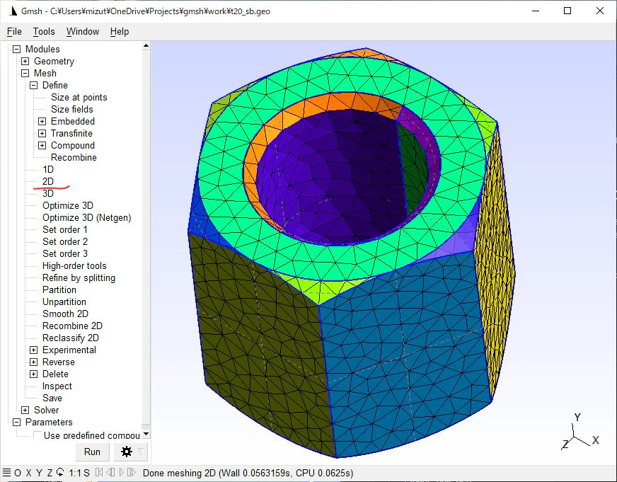
このファイルを gmsh の GUI に読み込んで,Mesh の下の 2D を押すと次のようなメッシュが作成できます.(自分のインストール 4.8.4 では,キーボードの2 がこの 2Dメッシュ作成のショートカットキーになっていました.)表面要素を色付けした表示にしたければ, [Tools] - [Options] で Mesh のパネルを選び,2D element faces の チェックを入れる必要があるかもしれません.
この例では黄緑の小さな三角形状の鋭角部分に小さなメッシュができてしまっています.形状再現性を少し犠牲にしても,小さなメッシュが生成されることを避けたいときに登場するのが Compound surface です.
面番号を調べる
compound surface の指定をするには CAD を読み込んだときに Geometry の Surface に割り当てられる面の番号を把握する必要があります。
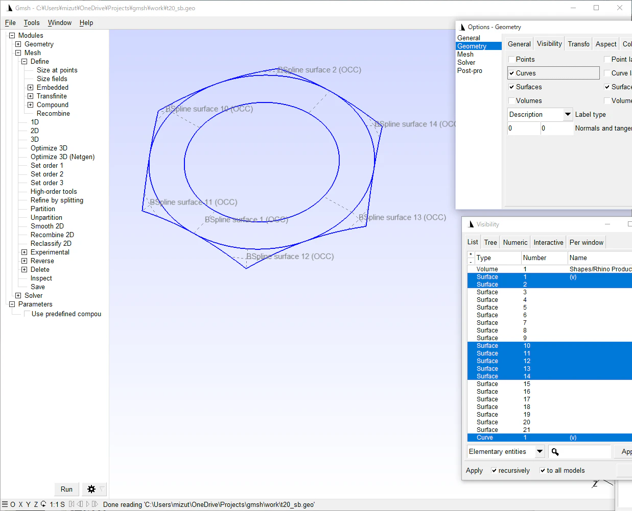
[Tools] [Visibility] を選んで Surface 1 をクリック(その段階では選択は反映されません),そのあと下矢印キーで選択要素を切り替えていくことで番号を把握できます.(どこかにメモしましょう.)
もっと複雑な形状でそもそもメッシュが切れないような状況では,Geometry のラベルを探す必要があるかもしれません.[Tools] - [Options] で Geometry のパネルを選び,Curves と Surfaces と Surface labels にチェックを入れると,形状と面の番号が表示されます.
選択した面を確認するためには,Visibility のウインドウで、該当する Surface を複数選択 (Ctrl キーを押しながらクリック) して Visibility の Apply ボタンを押せば画面でチェックできるでしょう.
compound surface の指定
面番号を列挙して、以下のように指定します.(上の説明図に対して,穴内側の面取りも追加しました。)
Compound Surface{1, 2, 10, 11, 12, 13, 14, 19, 20};
compound surface を使うかどうかを GUI の Parameters の中で選択できるように,少しだけコードを書きました.
// t20_sb.geo
SetFactory("OpenCASCADE");

v() = ShapeFromFile("t20_data.step");
Mesh.MeshSizeMin = 3;
Mesh.MeshSizeMax = 3;

cs = DefineNumber[0, Choices{0,1},
    Name "Parameters/Use predefined compound surface?" ];
  If(cs)
    Compound Surface{1, 2, 10, 11, 12, 13, 14, 19, 20};
  EndIf
GUI でこのファイルを読み込み, Parameters の Use predefined compound surface? をチェックしてから Mesh / 2D を選ぶと次のようなメッシュが得られました.

上面のメッシュから、小さな要素が無くなりました.
付録: gmsh 2 と gmsh 4 の差異
参照した文書 1 からリンクされているコードは,gmsh 4 系ではそのままでは動きませんでしたが,以下のように compound surface の指定と surface Loop の指定を微修正することで動作を確認できました.
// Compound Surface(60) = { 12:17 };
// Compound Surface(61) = { 18:23 };
// Compound Surface(62) = { 24:59 };
Compound Surface{12:17};
Compound Surface{18:23};
Compound Surface{24:59};

// Surface Loop(1) = { 6:11, 60, 61, 62 };
Surface Loop(1) = { 6:59 };
コードを修正したのは末尾付近の4行です. ▶ でコード全体表示
Geometry.Tolerance=1.0e-3;
Mesh.ElementOrder=1;
Mesh.RemeshParametrization=0;
Mesh.RemeshAlgorithm=1;
Mesh.Algorithm=5;
Mesh.Algorithm3D=1;
Mesh.Optimize=1;
Mesh.Remove4Triangles = 1;
Mesh.CharacteristicLengthFromPoints=0;
Mesh.CharacteristicLengthFromCurvature=0;
Mesh.CharacteristicLengthExtendFromBoundary=0;
Mesh.CharacteristicLengthMin = 0.1;
Mesh.CharacteristicLengthMax = 1.0;
Mesh.VolumeFaces=1;

Field[1] = MathEval;
Field[1].F = "0.25";
Background Field = 1;

Point(1) = { 0.0, 0.0, 0.5 };
Point(2) = { 0.0, 0.0, 0.0 };

For i In {0:5}
 r0 = Pi*i/3.0;
 r1 = Pi*i/3.0 - Pi/6.0;
 r2 = Pi*i/3.0 + Pi/6.0;
 Point(i+ 6) = { 0.5*Cos(r0),             0.5*Sin(r0),             0.5 };
 Point(i+12) = { 1.0*Cos(r0),             1.0*Sin(r0),             0.5 };
 Point(i+18) = { 1.0*Cos(r0),             1.0*Sin(r0),             0.4 };
 Point(i+24) = { 1.0*Cos(r0)+0.1*Cos(r1), 1.0*Sin(r0)+0.1*Sin(r1), 0.4 };
 Point(i+30) = { 1.0*Cos(r0)+0.1*Cos(r2), 1.0*Sin(r0)+0.1*Sin(r2), 0.4 };
 Point(i+36) = { 1.0*Cos(r0)+0.1*Cos(r1), 1.0*Sin(r0)+0.1*Sin(r1), 0.1 };
 Point(i+42) = { 1.0*Cos(r0)+0.1*Cos(r2), 1.0*Sin(r0)+0.1*Sin(r2), 0.1 };
 Point(i+48) = { 1.0*Cos(r0),             1.0*Sin(r0),             0.1 };
 Point(i+54) = { 1.0*Cos(r0),             1.0*Sin(r0),             0.0 };
 Point(i+60) = { 0.5*Cos(r0),             0.5*Sin(r0),             0.0 };
EndFor

For i In {0:5}
 j = Modulo(i+1,6);
 Line(i+ 6) = { i+60, i+ 6 };
 Line(i+12) = { i+ 6, i+12 };
 Line(i+18) = { i+60, i+54 };
 Line(i+24) = { i+36, i+24 };
 Line(i+30) = { i+42, i+30 };
 Line(i+36) = { i+12, j+12 };
 Line(i+42) = { i+30, j+24 };
 Line(i+48) = { i+42, j+36 };
 Line(i+54) = { i+54, j+54 };

 Circle(i+ 60) = { i+ 6, 1, j+ 6 };
 Circle(i+ 66) = { i+60, 2, j+60 };
 Circle(i+ 72) = { i+24, i+18, i+12 };
 Circle(i+ 78) = { i+30, i+18, i+12 };
 Circle(i+ 84) = { i+24, i+18, i+30 };
 Circle(i+ 90) = { i+36, i+48, i+42 };
 Circle(i+ 96) = { i+54, i+48, i+36 };
 Circle(i+102) = { i+54, i+48, i+42 };
EndFor

For i In {0:5}
 j = Modulo(i+1,6);

 Line Loop(i+ 6) = {   i+ 6,    i+ 60,  -(j+ 6), -(i+66) };
 Line Loop(i+12) = {   i+12,    i+ 36,  -(j+12), -(i+60) };
 Line Loop(i+18) = { -(i+18),   i+ 66,    j+18,  -(i+54) };
 Line Loop(i+24) = { -(i+42), -(i+ 30),   i+48,    j+24 };
 Line Loop(i+30) = { -(i+36), -(i+ 78),   i+42,    j+72 };
 Line Loop(i+36) = { -(i+48), -(i+102),   i+54,    j+96 };
 Line Loop(i+42) = { -(i+24),   i+ 90,    i+30,  -(i+84) };
 Line Loop(i+48) = { -(i+72),   i+ 84,    i+78  };
 Line Loop(i+54) = {   i+102, -(i+ 90), -(i+96) };

 Ruled Surface(i+ 6) = { i+ 6 };  // inner cylinder
 Plane Surface(i+12) = { i+12 };  // top face
 Plane Surface(i+18) = { i+18 };  // bottom face
 Plane Surface(i+24) = { i+24 };  // side face
 Ruled Surface(i+30) = { i+30 };  // fillet (top-side edge)
 Ruled Surface(i+36) = { i+36 };  // fillet (side-bottom edge)
 Ruled Surface(i+42) = { i+42 };  // fillet (side-side edge)
 Ruled Surface(i+48) = { i+48 } In Sphere { i+18 }; // fillet (top corner)
 Ruled Surface(i+54) = { i+54 } In Sphere { i+48 }; // fillet (bottom corner)
EndFor

// Compound Surface(60) = { 12:17 };
// Compound Surface(61) = { 18:23 };
// Compound Surface(62) = { 24:59 };
Compound Surface{12:17};
Compound Surface{18:23};
Compound Surface{24:59};

// Surface Loop(1) = { 6:11, 60, 61, 62 };
Surface Loop(1) = { 6:59 };

Volume(1) = {1};
Physical Volume("all") = {1};
まとめ
CAD から持ってきた形状にメッシュを切る際に、用途によっては compound surface の出番がありそうです.ただ自動で処理するには,面番号の認識にかなりの工夫が要りそうです.
-
GmshでCompound Surfaceを使う | https://www.hanabusa.net/hpc/gmsh/compound.html ↩ ↩2