(Felica/Mifare/NFC チャレンジシリーズ) その他の記事はこちら 「Felica/Mifare/NFC でいろいろ実験」
https://qiita.com/nanbuwks/items/1f416d6e45a87250ee0a
カードリーダーを作る
あるところに、カードリーダーを使った旧いシステムがありました。
- Myrare カード
- 特定のセクタを特定のキーで読んで処理をする
- 特注品のカードリーダーを使う
- カードリーダー用の DLL を使ってデスクトップアプリから利用
ところがカードリーダーがディスコン、DLLも 32bit のみの提供ということで、どうしよう。
ということで、新しいカードリーダーを作ることにしました。
デスクトップアプリも今時 Web アプリだよね。
Webアプリということなら、カードリーダーの出力方法は HID キーボードデバイスでいいよね。
ということで、ここらへんを集めて作りました。
「STM32F103でHIDデバイス」
https://qiita.com/nanbuwks/items/f7f2377c2b252e936baa
「Arduino ESP32 と STM32 で NFC RFID-RC522」
https://qiita.com/nanbuwks/items/96c3c2d2af2cf97f3797
「1602 キャラクタ LCDモジュール を STM32 と RaspberryPi で動かす」
https://qiita.com/nanbuwks/items/d5f094e54a3f6641c970
動作
- カードリード
- ぴっと鳴る
- 内容をLCDに表示する
- HIDデバイスで出力する
というようにしました。
カードリーダの選定
- SONY の FeliCa リーダー・ライター RC-S620S
総務省の型式指定もあるしこれにしようかな・・・と思ったけれども検討した当時品切れで次回入荷未定になってました。
これ以外だと形式指定のないものになってしまいます。
- element14 の EXPLORE-NFC-WW
入手性が悪いので見送り
- RFID-RC522
Felicaには対応していませんでしたが知見の多そうなこれで進めることにしました。
マイコンの選定
カードリーダーが 3.3V バス であること、HIDキーボードを使うことことから 3.3V の Arduno Leonardo ないし互換機を使おうとしましたが、手持ちが 5V のものしか無かったので STM32ボードを使いました。
「Tips of RobotDyn STM32F103 Dev.Board」
https://qiita.com/lowlevel/items/47b0a8ba17f8afc473a6
プログラム
STM32_Arduino 環境で作ったソースはこれです。
#include <SPI.h>
#include <MFRC522.h>
#include <LiquidCrystal.h>
#include <USBComposite.h>

const int rs = PB11, en = PB10, d4 = PB0, d5 = PB1, d6 = PC13, d7 = PC14; //STM32 Pins to which LCD is connected
LiquidCrystal lcd(rs, en, d4, d5, d6, d7); //Initialize the LCD

#define BUZZER          PA8
#define RST_PIN         PA3           // Configurable, see typical pin layout above
#define SS_PIN          PA4         // Configurable, see typical pin layout above

MFRC522 mfrc522(SS_PIN, RST_PIN);   // Create MFRC522 instance.
MFRC522::MIFARE_Key key;
USBHID HID;
HIDKeyboard Keyboard(HID);


void setup() {
    Serial1.begin(115200);
    HID.begin(HID_KEYBOARD_MOUSE);
    lcd.begin(16, 2);//Defining 16*2 LCD
    lcd.setCursor(0, 0); //LCD Row 0 and Column 0
    lcd.print("Ready...");
    delay(3000);
    Serial1.println(F("Scan a MIFARE Classic PICC to serial and HID."));
    SPI.begin();        // Init SPI bus
    mfrc522.PCD_Init(); // Init MFRC522 card
    key.keyByte[0] = 0xFF;
    key.keyByte[1] = 0xFF;
    key.keyByte[2] = 0xFF;
    key.keyByte[3] = 0xFF;
    key.keyByte[4] = 0xFF;
    key.keyByte[5] = 0xFF;
    Serial1.println("Ready...");
    pinMode(BUZZER,OUTPUT); // buzzer
}

/**
 * Main loop.
 */
void loop() {
    Serial1.println("waiting1...");
    delay(100);
    // Reset the loop if no new card present on the sensor/reader. This saves the entire process when idle.
    if ( ! mfrc522.PICC_IsNewCardPresent())
        return;

    // Select one of the cards
    Serial1.println("waiting2...");
    if ( ! mfrc522.PICC_ReadCardSerial())
        return;

    // Show some details of the PICC (that is: the tag/card)
    Serial1.println("waiting3...");
    Serial1.print(F("Card UID:"));
    dump_byte_array(mfrc522.uid.uidByte, mfrc522.uid.size);
    Serial1.println();
    Serial1.print(F("PICC type: "));
    MFRC522::PICC_Type piccType = mfrc522.PICC_GetType(mfrc522.uid.sak);
    Serial1.println(mfrc522.PICC_GetTypeName(piccType));

    // Check for compatibility
    if (    piccType != MFRC522::PICC_TYPE_MIFARE_MINI
        &&  piccType != MFRC522::PICC_TYPE_MIFARE_1K
        &&  piccType != MFRC522::PICC_TYPE_MIFARE_4K) {
        Serial1.println(F("This sample only works with MIFARE Classic cards."));
        return;
    }

    // In this sample we use the second sector,
    // that is: sector #1, covering block #4 up to and including block #7
    byte sector         = 2;
    byte blockAddr      = 8;
    byte trailerBlock   = 11;
    MFRC522::StatusCode status;
    byte buffer[18];
    byte size = sizeof(buffer);

    // Authenticate using key A
    Serial1.println(F("Authenticating using key A..."));
    status = (MFRC522::StatusCode) mfrc522.PCD_Authenticate(MFRC522::PICC_CMD_MF_AUTH_KEY_A, trailerBlock, &key, &(mfrc522.uid));
    if (status != MFRC522::STATUS_OK) {
        Serial1.print(F("PCD_Authenticate() failed: "));
        Serial1.println(mfrc522.GetStatusCodeName(status));
        return;
    }
    digitalWrite(BUZZER,HIGH);
    // Read data from the block
    Serial1.print(F("Reading data from block ")); Serial1.print(blockAddr);
    Serial1.println(F(" ..."));
    status = (MFRC522::StatusCode) mfrc522.MIFARE_Read(blockAddr, buffer, &size);
    if (status != MFRC522::STATUS_OK) {
        Serial.print(F("MIFARE_Read() failed: "));
        Serial.println(mfrc522.GetStatusCodeName(status));
    }
    Serial1.print(F("Data in block ")); Serial1.print(blockAddr); Serial1.println(F(":"));
    dump_byte_array(buffer, 16); Serial1.println();
    Serial1.println();
    lcd.clear();
    lcd.setCursor(0, 0); //LCD Row 0 and Column 0
    buffer[10]=0;
    String msg = String((char*) buffer);
    lcd.print(msg);
    Keyboard.println(msg);
    digitalWrite(BUZZER,HIGH);
    delay(140);
    digitalWrite(BUZZER,LOW);
    delay(3000);
    lcd.clear();
    lcd.setCursor(0, 0); //LCD Row 0 and Column 0
    lcd.print("Ready...");
    // Halt PICC
    mfrc522.PICC_HaltA();
    // Stop encryption on PCD
    mfrc522.PCD_StopCrypto1();
}

/**
 * Helper routine to dump a byte array as hex values to Serial.
 */
void dump_byte_array(byte *buffer, byte bufferSize) {
    for (byte i = 0; i < bufferSize; i++) {
        Serial1.print(buffer[i] < 0x10 ? " 0" : " ");
        Serial1.print(buffer[i], HEX);
    }
}
このプログラムではセクター( blockAddr ) 8 の ASCII 内容10バイトが Key_A (0xFFFFFF) を使って読み出されます。
ハードウェア
基板を起こしました。
|STM32 Dev. BOARD|RFID-RC522|
|---|---|---|
|3V3|3.3V|
|PA3|RST|
|GND|GND|
|(NC)|IRQ|
|PA6|MISO|
|PA7|MOSI|
|PA5|SCK |
|PA4|SDA |
| LCD PIN | SIGNAL NAME | STM32 |
|---|---|---|
| 1 | VSS | GND |
| 2 | VDD | 3.3V |
| 3 | VO | (Volume) |
| 4 | RS | PB11 |
| 5 | R/W | GND |
| 6 | E | PB10 |
| 7 | D0 | (NC) |
| 8 | D1 | (NC) |
| 9 | D2 | (NC) |
| 10 | D3 | (NC) |
| 11 | D4 | PB0 |
| 12 | D5 | PB1 |
| 13 | D6 | PC13 |
| 14 | D7 | PC14 |
| 15 | LED(+) | 3.3V |
| 16 | LED(-) | GND |
| BUZZER | STM32 |
|---|---|
| + | PA8 |
| - | GND |
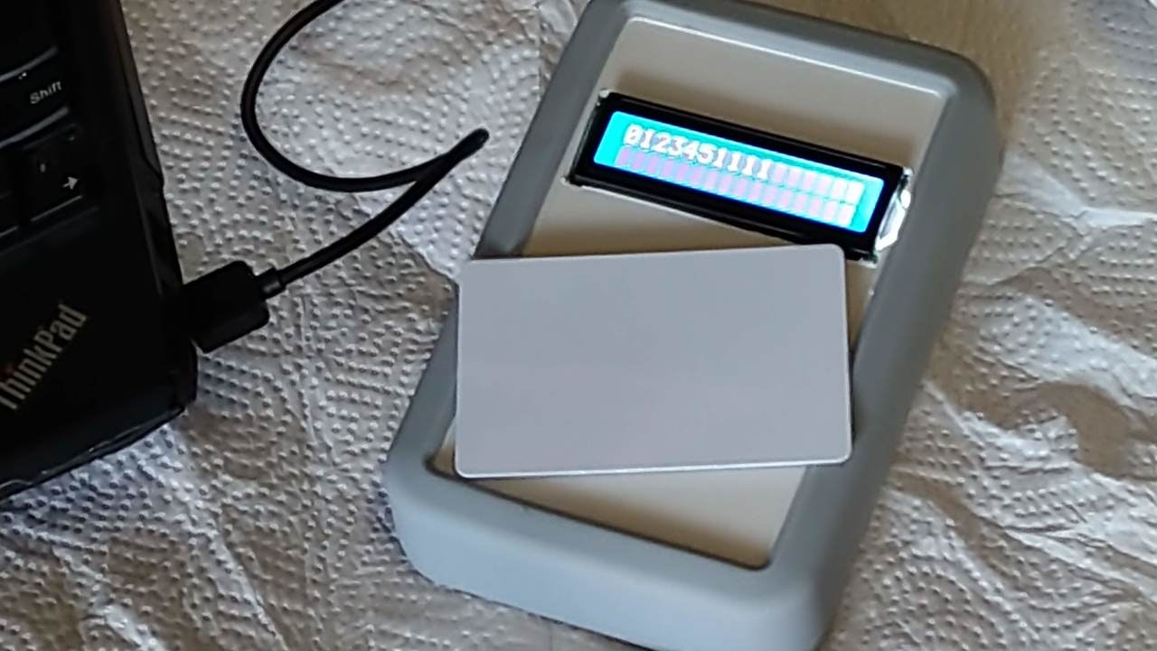
動作
無事OK!
電波強度の調整などは後ほど行っていきます。
