概要
-
TinyWireSを使用して、DigisparkをI2CのSlaveとして使用する- =>
TinyWireSのインストール、サンプルスケッチ
- =>
-
Raspberry Pi 2(I2C Master)と接続して、通信テストする。
- => Raspbian Jessie Lite(2015-11-21)ベースで、I2Cを使う設定とツール
i2c-toolsのインストール
- => Raspbian Jessie Lite(2015-11-21)ベースで、I2Cを使う設定とツール
-
#ラズパイに
ADCがない! => 手元にあるATTiny85のADCの値をI2Cで受け渡せば... ってのが動機。
環境
- DigiSpark(互換品)
- Arduinoソフトウェア 1.6.6 + Windows 10 ("[メモ] Digispark(ATTiny85) Arduino開発環境で、Lチカ" を参考に)
- RaspberryPi2 (I2C Masterとして使用
i2c-tools)
ATTiny85
TinyWireSライブラリの準備
-
https://github.com/rambo/TinyWire から、
gitか、[Download ZIP]でファイルを取得する(ZIPは解凍する) - Arduinoソフトウェアを起動
- スケッチ-> Include Library -> Add ZIP Library...を選択
- ファイル選択ダイアログから、
TinyWireSのフォルダを選択
サンプルコード
- attiny85_i2c_slave.inoをベースにちょっと変更したもの
- Slaveアドレスは
0x5A - 4バイトのデータを保持。
- それぞれ0x00,0x01,0x02,0x03のデータアドレスから設定・取得 default = {0xDE, 0xAD, 0xBE, 0xEF}
# define I2C_SLAVE_ADDRESS 0x5A // the 7-bit address
# define LED_PIN         1      // DigiSpark LED pin

# include "TinyWireS.h"

# ifndef TWI_RX_BUFFER_SIZE
# define TWI_RX_BUFFER_SIZE ( 16 )
# endif

volatile uint8_t i2c_regs[] =
{
    0xDE,
    0xAD,
    0xBE,
    0xEF,
};

volatile byte reg_position;
const byte reg_size = sizeof(i2c_regs);

void requestEvent()
{
    reg_position %= reg_size;
    TinyWireS.send(i2c_regs[reg_position]);
    reg_position++;
}

void receiveEvent(uint8_t howMany)
{
    // Sanity check
    if ((howMany < 1) || (howMany > TWI_RX_BUFFER_SIZE)) return;

    reg_position = TinyWireS.receive();
    howMany--;

    while(howMany--)
    {
        reg_position %= reg_size;
        i2c_regs[reg_position] = TinyWireS.receive();
        reg_position++;
    }
}

void setup(){
    pinMode(LED_PIN,OUTPUT);
    mt08Blink(LED_PIN, 2);               //開始時LED点滅

    TinyWireS.begin(I2C_SLAVE_ADDRESS);
    TinyWireS.onReceive(receiveEvent);
    TinyWireS.onRequest(requestEvent);
}

void loop()
{
    TinyWireS_stop_check();
}

void mt08Blink(byte led, byte times)
{
  times *= 2;
  while(times > 0) {
    digitalWrite(led,(times & 0x01) ? LOW : HIGH);
    delay (200);
    times--;
  }
}
Raspberry Pi 2
- Raspbian:
2015-11-21-raspbian-jessie-lite - i2cの設定
初期設定
-
microSDにJessie Liteのイメージをいれて、起動
-
sudo raspi-configで設定1 Expand Filesystem-
5 Internationalisation OptionsI2 Change Timezone
-
9 Advanced OptionsA2 Hostname-
A7 I2C=><Yes>=><OK>=><Yes>(I2Cを使えるようにする)
- リブート => Yes
-
i2c-toolsのインストール
sudo apt-get update
sudo apt-get install i2c-tools
4. WiFi設定(必要あれば)

    ```
% sudo iwlist wlan0 scan
% sudo su
% wpa_passphrase SSID 'KEY' >> /etc/wpa_supplicant/wpa_supplicant.conf
###
# Wifiの素のパスワードを消す
sudo vi /etc/wpa_supplicant/wpa_supplicant.conf
-
swap無効(必要あれば)
sudo dphys-swapfile uninstall
sudo dpkg --purge dphys-swapfile
sudo rm -f /var/swap
6. リブート (`% sudo reboot`)
## 接続
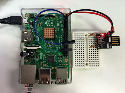
| ATTiny85 | . |RaspberryPi |
|---:|:--:|:---|
|P0(SDA)| 330Ω (適当な抵抗)| 3番ピンSDA |
|P2(SCL)| 330Ω (適当な抵抗)| 5番ピンSCL|
|5V | -- |2または4番ピン(5V) |
|GND | -- |6または9番ピン(GND) |
- IOの電圧が、ATTiny85の5V、RaspberryPi3.3Vなので、間に適当な抵抗。
- RaspberryPi側でSDA,SCLはR23,R24によりpull-upされてる<br>
参考:
https://www.raspberrypi.org/documentation/hardware/raspberrypi/schematics/Raspberry-Pi-B-Plus-V1.2-Schematics.pdf
## テスト
- `i2cdetect` : 接続されているSlaveのリスト
- `i2cget` : データの読み出し
- `i2cset` : データの書き込み
```shell-session
pi@raspberrypi:~ $ i2cdetect -y 1
0 1 2 3 4 5 6 7 8 9 a b c d e f
00: -- -- -- -- -- -- -- -- -- -- -- -- --
10: -- -- -- -- -- -- -- -- -- -- -- -- -- -- -- --
20: -- -- -- -- -- -- -- -- -- -- -- -- -- -- -- --
30: -- -- -- -- -- -- -- -- -- -- -- -- -- -- -- --
40: -- -- -- -- -- -- -- -- -- -- -- -- -- -- -- --
50: -- -- -- -- -- -- -- -- -- -- 5a -- -- -- -- --
60: -- -- -- -- -- -- -- -- -- -- -- -- -- -- -- --
70: -- -- -- -- -- -- -- --
pi@raspberrypi:~$ i2cget -y 1 0x5a 0x00
0xde
pi@raspberrypi:~$ i2cget -y 1 0x5a 0x01
0xad
pi@raspberrypi:~$ i2cget -y 1 0x5a 0x02
0xbe
pi@raspberrypi:~$ i2cget -y 1 0x5a 0x03
0xef
pi@raspberrypi:~$ i2cget -y 1 0x5a 0x00 w
0xadde
pi@raspberrypi:~$ i2cget -y 1 0x5a 0x02 w
0xefbe
pi@raspberrypi:~$ i2cget -y 1 0x5a 0x03 w
0xdeef
pi@raspberrypi:~ $ i2cset -y 1 0x5a 0x00 0x15
pi@raspberrypi:~ $ i2cset -y 1 0x5a 0x01 0x26
pi@raspberrypi:~ $ i2cset -y 1 0x5a 0x02 0x37
pi@raspberrypi:~ $ i2cset -y 1 0x5a 0x03 0x48
pi@raspberrypi:~ $ i2cget -y 1 0x5a 0x00
0x15
pi@raspberrypi:~ $ i2cget -y 1 0x5a 0x01
0x26
pi@raspberrypi:~ $ i2cget -y 1 0x5a 0x02
0x37
pi@raspberrypi:~ $ i2cget -y 1 0x5a 0x03
0x48
pi@raspberrypi:~ $
メモ
-
Raspberry PiのでI2CのDefaultのバススピードは、100000(100kHz)らしい。
-
変更するには、以下のようにするらしい。
32kHzにバススピード変更
sudo rmmod i2c_bcm2708
sudo modprobe i2c_bcm2708 baudrate=32000