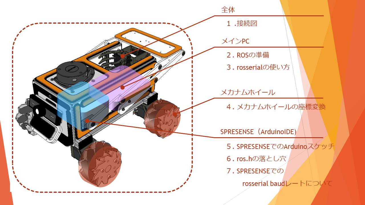
本章の流れ
実施環境
OS : Ubuntu16.04LTS. , Ubuntu18.04LTS.
ROS環境 : kinetic , melodic
対象PC :LattepandaAlphaによる動作(Intel Core m3-7y30 程度の動作)を想定
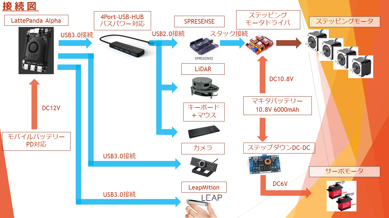
1.接続図
メインPCであるLattePandaAlphaからUSBでSPRESENSEに接続し、SPRESENSEと接続されたArduino用
CNC拡張ボード上に載せたステッピングモータドライバ(TB67S249FTG)にステップパルスを送ります。送られた
ステップパルスの数量に合わせてモータが回転し、ロボットの姿勢を制御します。またメインPCにUSB接続された
LiDARによってSLAM、AMCLを行っています。更にWEBカメラやLeapMotionもROSに組み込んでいます。

ここでの注意!!
ステッピングモータドライバについて、これ以外にも様々試してみました。その結果、選び出したのが
TB67S249FTGです。
このステッピングモータドライバはWEBで記載されている通り、ステッピングモータの脱調防止や、スピードに合わせた
電流制御をドライバ側でかなり行ってくれるため、様々起こるであろう問題点を無かった事にしてくれる、とても
インテリジェントなドライバです。
実はここに至るまでには長い道のりがあり、ここだけでも1章書き上げることが出来てしまう位に試してみました。。。
中には1個1000円以上するモータドライバ×4個を一瞬で破壊し、途方に暮れることもありました。。。
そのため、TB67S249FTGか、DRV8825 (1個200円程度で安価だが消費電力、最大出力で劣るドライバ) で使用することを
お勧めします。くれぐれもモータに流す電流はデータシートで確認し、電流調整した後動かすようにして下さい。
更にモータドライバの発熱量は他の部品よりも高く、ヒートシンクを取り付け、他の部品との物理的な距離を
確保するよう配置して下さい。
ここでご紹介したステッピングモータドライバの電流調整方法は、こちらなどが参考になります。
ステッピングモータドライバ電流調整方法 youtube動画
TB67S249FTGの場合:電流=V$\tiny{REF}$×1.25 A/V
DRV8825の場合:電流=V$\tiny{REF}$×1.5 A/V となっています。
もしモータドライバを壊してしまっても自己責任でお願い致します。
2.ROSの準備
ROSの準備については様々な資料やWEBサイトで紹介されているため割愛しますが、
私はROS kineticのインストールについて以下を参考に行いました。
ROS講座02 インストール
また、これから使うrosserialについてはこちらを参考にして下さい。
ROSのrosserialを使ってArduinoでLチカをする
3.rosserialの使い方
rosserialは参考にした内容よりターミナルで以下を実行しております。
roscore
rosrun rosserial_python serial_node.py
4.メカナムホイールの座標変換
ここで重要となるのが以下で記述している①、②の行列式となります。行列式の参考として以下の資料が
役に立ちました。
その際メカナムホイールロボットの動かし方について、ざっと記述してみます。
①topic名は /cmd_vel (Vx,Vyの直線的な速度に加え、Wzの角速度を持った指令) をsubscribeし、
4隅に配置されたメカナムホイールの回転速度に行列変換し姿勢を制御する。
②4個のメカナムホイールの回転量から逆列変換して、現在位置となるtfをROSに送る。
③関係無いかも知れませんが、/cmd_velにあるlinear_zの値を使ってロボットアームを上下に動かしています。
5.SPRESENSEでのArduinoスケッチ
それでは、これを基に記述したArduinoスケッチをご確認ください。
※ゴチャゴチャと書いているのでご了承ください。。。
# include <ros.h>
# include <ros/time.h>
# include <geometry_msgs/Twist.h>
# include <std_msgs/String.h>
# include <tf/tf.h>
# include <tf/transform_broadcaster.h>
# include <nav_msgs/Odometry.h>
# include <Wire.h>
# include <sensor_msgs/Imu.h>
# include <nav_msgs/Odometry.h>

# include <Adafruit_PWMServoDriver.h>

//-----ROS変数---------------------------------------------------------------------------------------
ros::NodeHandle nh;
std_msgs::String str_msg;
nav_msgs::Odometry odom;
ros::Publisher odom_pub("odom",&odom);
geometry_msgs::TransformStamped tf_arduino;
tf::TransformBroadcaster broadcaster;
const float pi=3.14159;

//cmd_vel用
float linear_x=0.000;//speed x [m]
float linear_y=0.0;//speed y [m]
float linear_z=0.0;//speed y [m]
float angle_z=0.00;//speed z [rad/s]

//odom用
float x;
float y;
float theta=0;
float dx;
float dy;
float dtheta;
unsigned long current_time,last_time;

//座標変換用
float w[4]         = {0.0001,0.0001,0.0001,0.0001} ;//回転速度w [rad/s]
float motor_vel[4] = {0.001 ,0.001 ,0.001 ,0.001 } ;// [mm/s]
float a[4][3];//スピード→モータ回転 変換行列
float b[3][4];//モータ回転→スピード 変換行列
const float alpha=45;//メカナムホイールのローラ角度[deg]

//Arduino用CNC拡張ボード用ピン番号
const int motor_step_pin[4]={2,3,4,12};//ステッピングモータ ピン番号
const int direct_pin[4]={5,6,7,13};    //CW,CCWピン番号

//pidパラメータ
float target[4]={0.1,0.1,0.1,0.1};
float duty[4] = {0.1,0.1,0.1,0.1};
float preTime[4]={100,100,100,100};
float P[4],I[4],D[4];
float preP[4]={0,0,0,0};
float dt[4]={0.001,0.001,0.001,0.001};
float Kp=0.001,Ki=0.00004 ,Kd=0.00098;
float motor_target_speed[4]={0,0,0,0};

//cmd_vel から メカナムホイール回転数に変換するための変数
const float wheel_radius=0.050;//ホイール半径0.050[m] 単位はmとする
const float ww=0.13;//width/2 [m]
const float lw=0.115;//length/2 [m]
const float motor_step=3200;//ステッピングモータの1回転当たりのステップ数(マイクロステップ制御込みのステップ数)
//(ステッピングモータ1回転200パルス)÷(マイクロステップ1/16)=3200
float step_time[4]={5000,5000,5000,5000};//各モータのステップパルスのON/OFF間隔[μs]
float step_current_time[4];
float step_last_time[4];
boolean step_flip[4]={LOW,LOW,LOW,LOW};//各モータのステップパルスのON/OFF状態
float step_count[4]={0,0,0,0};//各モータのステップパルス量をカウントする
float last_step_count[4]={0,0,0,0};
float delta_step_count[4]={0,0,0,0};
float wx[4];
float wy[4];
float wz[4];

//ロボットアーム用(サーボモジュール PCA9685使用)
Adafruit_PWMServoDriver pwm = Adafruit_PWMServoDriver();
# define ARM_SERVOMIN  150 // this is the 'minimum' pulse length count (out of 4096)
# define ARM_SERVOMAX  500 // this is the 'maximum' pulse length count (out of 4096)
# define GRIP_SERVOMIN  110 // this is the 'minimum' pulse length count (out of 4096)
# define GRIP_SERVOMAX  300 // this is the 'maximum' pulse length count (out of 4096)
uint8_t servonum = 0;
float arm_angle=0;
//----------------------------ROS  callback----------------------------------------------------
void messageCb(const geometry_msgs::Twist& twist) {
  linear_x = twist.linear.x;
  linear_y = twist.linear.y;
  linear_z = twist.linear.z;
  angle_z = twist.angular.z;
}
ros::Subscriber<geometry_msgs::Twist> sub("cmd_vel", &messageCb);


void setup(){
  //出力ピン設定
  pinMode(motor_step_pin[0], OUTPUT);
  pinMode(motor_step_pin[1], OUTPUT);
  pinMode(motor_step_pin[2], OUTPUT);
  pinMode(motor_step_pin[3], OUTPUT);

  pinMode(direct_pin[0], OUTPUT);
  pinMode(direct_pin[1], OUTPUT);
  pinMode(direct_pin[2], OUTPUT);
  pinMode(direct_pin[3], OUTPUT);
  //ROSの初期設定
  nh.getHardware()->setBaud(1000000);//baudrateを1Mbpsに設定
  nh.initNode();
  broadcaster.init(nh);
  nh.advertise(odom_pub);
  initOdom();
  nh.subscribe(sub);

  //アーム用サーボモータの初期値を設定する
  pwm.begin();
  pwm.setPWMFreq(60);
  pwm.setPWM(0, 0, map(172, 0, 180, ARM_SERVOMIN  , ARM_SERVOMAX));
  pwm.setPWM(1, 0, map(  0, 0, 180, ARM_SERVOMIN  , ARM_SERVOMAX));
  pwm.setPWM(4, 0, map( 15, 0, 180, GRIP_SERVOMIN , GRIP_SERVOMAX));
  pwm.setPWM(5, 0, map(150, 0, 180, GRIP_SERVOMIN , GRIP_SERVOMAX));
  delay(100);
  nh.loginfo("ROS wake up!!");

  //cmd_velの速度情報をモータの回転数に変換するための行列式
  a[0][0]=  1/(wheel_radius*tan(alpha/180*pi)) ; a[0][1]= 1/wheel_radius ; a[0][2]=(-1*(lw+ww)/(wheel_radius));
  a[1][0]=  1/(wheel_radius*tan(alpha/180*pi)) ; a[1][1]=-1/wheel_radius ; a[1][2]=    (lw+ww)/(wheel_radius) ;
  a[2][0]=  1/(wheel_radius*tan(alpha/180*pi)) ; a[2][1]=-1/wheel_radius ; a[2][2]=(-1*(lw+ww)/(wheel_radius));
  a[3][0]=  1/(wheel_radius*tan(alpha/180*pi)) ; a[3][1]= 1/wheel_radius ; a[3][2]=    (lw+ww)/(wheel_radius) ;

  //モータの回転数からtfの座標を作り出すための行列式
  b[0][0]=   wheel_radius             ; b[0][1]=   wheel_radius          ; b[0][2]=   wheel_radius          ; b[0][3]=  wheel_radius        ;
  b[1][0]=   wheel_radius             ; b[1][1]= - wheel_radius          ; b[1][2]= - wheel_radius          ; b[1][3]=  wheel_radius        ;
  b[2][0]= - wheel_radius/(lw+ww)     ; b[2][1]=  wheel_radius/(lw+ww)  ; b[2][2]=  -wheel_radius/(lw+ww)  ;  b[2][3]=  wheel_radius/(lw+ww);

  last_time = micros();
  current_time = micros();
  step_current_time[0]=step_current_time[1]=step_current_time[2]=step_current_time[3]= micros();
  step_last_time[0]=step_last_time[1]=step_last_time[2]=step_last_time[3]= micros();
}

//speed_cal()でcmd_velからの要求スピードを各モータの移動スピードmotor_vel[]に変換する
void speed_cal(){
  motor_vel[0]=(a[0][0]*linear_x + a[0][1]*linear_y + a[0][2]*angle_z) *wheel_radius*pi ; //[m/s]
  motor_vel[1]=(a[1][0]*linear_x + a[1][1]*linear_y + a[1][2]*angle_z) *wheel_radius*pi;  //[m/s]
  motor_vel[2]=(a[2][0]*linear_x + a[2][1]*linear_y + a[2][2]*angle_z) *wheel_radius*pi ; //[m/s]
  motor_vel[3]=(a[3][0]*linear_x + a[3][1]*linear_y + a[3][2]*angle_z) *wheel_radius*pi ; //[m/s]
}

//motor_vel[]を目標スピードとしてモータ速度duty[]を制御する
//モータ速度duty[]をステッピングモータのON/OFFタイミングstep_time[][μs]に変換する
void motor_pid(int num,float motor_call_speed){
/*
  motor_target_speed[num]=motor_call_speed;
  dt[num] = (micros() - preTime[num]) / 1000000;
  preTime[num] = micros();

  P[num]  = motor_target_speed[num] - duty[num];
  I[num] += P[num] * dt[num];
  D[num] = (P[num] - preP[num]) / dt[num];
  preP[num] = P[num];
  duty[num] += Kp * P[num] + Ki * I[num] + Kd * D[num];
*/
//↑マルチコアで使おうとしていた時の名残。負荷が大きいため現在は廃止。

  duty[num] =motor_call_speed;

  if(motor_call_speed>0 && duty[num]<0){
    duty[num]=-0.0001;
  }
  else if(motor_call_speed<0 && duty[num]>0){
    duty[num]=0.0001;
  }
  if(duty[num]==0){
    duty[num]=0.0001;
  }

  //motor_move(num,duty[num]); //pidで計算されたスピード値[mm]をmotor_moveに渡す
  //       (1秒/2)/(スピード[m/s]/(ホイール半径[m]*2*pi=周長[m])*1周のステップ数 )
  //↑の解釈:(1秒/2)/(1秒間でのホイール回転数[回転/s]*1周のステップ数[ステップ/回転]
  //↑の解釈:(1,000,000μ秒/2)/(1秒当たりのステップ数[ステップ/s])
  step_time[num]=abs(500000/(duty[num]/(wheel_radius*2*pi)*motor_step));

//以下はスピード制限
  if(step_time[num]<40){
    step_time[num]=40;
  }
  else if(step_time[num]>100000){
    step_time[num]=100000;
  }

}

//odometry計算
void odom_cal(){
  //各モータの微分ステップ数delta_step_countから微分回転数wにしている
  delta_step_count[0]=step_count[0] - last_step_count[0];
  delta_step_count[1]=step_count[1] - last_step_count[1];
  delta_step_count[2]=step_count[2] - last_step_count[2];
  delta_step_count[3]=step_count[3] - last_step_count[3];
  wx[0]              =b[0][0]*delta_step_count[0];
  wx[1]              =b[0][1]*delta_step_count[1];
  wx[2]              =b[0][2]*delta_step_count[2];
  wx[3]              =b[0][3]*delta_step_count[3];

  wy[0]              =b[1][0]*delta_step_count[0];
  wy[1]              =b[1][1]*delta_step_count[1];
  wy[2]              =b[1][2]*delta_step_count[2];
  wy[3]              =b[1][3]*delta_step_count[3];

  wz[0]              =b[2][0]*delta_step_count[0];
  wz[1]              =b[2][1]*delta_step_count[1];
  wz[2]              =b[2][2]*delta_step_count[2];
  wz[3]              =b[2][3]*delta_step_count[3];

  dx     = (wx[0]+wx[1]+wx[2]+wx[3])/4 /motor_step*wheel_radius*2*pi*4*1.24;//1.24は補正分
  dy     = (wy[0]+wy[1]+wy[2]+wy[3])/4 /motor_step*wheel_radius*2*pi*4*1.24;//1.24は補正分
  dtheta = (wz[0]-wz[1]-wz[2]+wz[3])/4 /motor_step*1.57;//1.57は補正分

  last_step_count[0]=step_count[0];
  last_step_count[1]=step_count[1];
  last_step_count[2]=step_count[2];
  last_step_count[3]=step_count[3];
   x     +=  dx*cos(theta+dtheta/2)-dy*sin(theta+dtheta/2);
   y     +=  dx*sin(theta+dtheta/2)+dy*cos(theta+dtheta/2);
   theta +=  dtheta;
   if(theta > 3.1415)
     theta=-3.1415;
}

//odometry初期化
void initOdom(void){
  x = 0.0;
  y = 0.0;
  theta = 0.0;
  dx=0.0;
  dy=0.0;
  dtheta=0.0;

  odom.pose.pose.position.x = 0.0;
  odom.pose.pose.position.y = 0.0;
  odom.pose.pose.position.z = 0.0;

  odom.pose.pose.orientation.x = 0.0;
  odom.pose.pose.orientation.y = 0.0;
  odom.pose.pose.orientation.z = 0.0;
  odom.pose.pose.orientation.w = 0.0;

  odom.twist.twist.linear.x  = 0.0;
  odom.twist.twist.linear.y  = 0.0;
  odom.twist.twist.angular.z = 0.0;
}

void loop(){
  nh.spinOnce(); //cmd_velから要求されるロボットのスピードを取得する
  speed_cal();  //要求されるロボットのスピードをホイールの回転数に変換する
  motor_pid(0,motor_vel[0]);//ホイールの回転数をステッピングモータのパルススピードに変換する
  motor_pid(1,motor_vel[1]);
  motor_pid(2,motor_vel[2]);
  motor_pid(3,motor_vel[3]);

  step_current_time[0]=step_current_time[1]=step_current_time[2]=step_current_time[3]= micros();

  //micros()時間が0に戻った時を想定し、クリアする
  if(step_current_time[0]<step_last_time[0]){
    step_last_time[0]=step_last_time[1]=step_last_time[2]=step_last_time[3]= micros();
    delayMicroseconds(100);
    step_current_time[0]=step_current_time[1]=step_current_time[2]=step_current_time[3]= micros();
  }

//------------------モーターのステップパルスをコントロール----------------------------------------
//モータ4個ををマルチタスク的に処理する
//各モータごとstep_time以上の時間が過ぎたらON/OFFを切り替え,モータを進ませる
//for文を使わず、なるべく平書きして処理を早くさせる(どれ位効果があるかは未確認)
  if(step_time[0]<(step_current_time[0]-step_last_time[0])){
    step_flip[0]=!step_flip[0];
    if(motor_vel[0]>0){
      digitalWrite(direct_pin[0],1);
      step_count[0]++;
    }else{
      digitalWrite(direct_pin[0],0);
      step_count[0]--;
    }
    step_last_time[0]=step_current_time[0];
  }

  if(step_time[1]<(step_current_time[1]-step_last_time[1])){
    step_flip[1]=!step_flip[1];
    if(motor_vel[1]>0){
      digitalWrite(direct_pin[1],0);
      step_count[1]++;
    }else{
      digitalWrite(direct_pin[1],1);
      step_count[1]--;
    }
    step_last_time[1]=step_current_time[1];
  }

  if(step_time[2]<(step_current_time[2]-step_last_time[2])){
    step_flip[2]=!step_flip[2];
    if(motor_vel[2]>0){
      digitalWrite(direct_pin[2],0);
      step_count[2]++;
    }else{
      digitalWrite(direct_pin[2],1);
      step_count[2]--;
    }
    step_last_time[2]=step_current_time[2];
  }

  if(step_time[3]<(step_current_time[3]-step_last_time[3])){
    step_flip[3]=!step_flip[3];
    if(motor_vel[3]>0){
      digitalWrite(direct_pin[3],1);
      step_count[3]++;
    }else{
      digitalWrite(direct_pin[3],0);
      step_count[3]--;
    }
    step_last_time[3]=step_current_time[3];
  }

  digitalWrite(motor_step_pin[0],step_flip[0]);
  digitalWrite(motor_step_pin[1],step_flip[1]);
  digitalWrite(motor_step_pin[2],step_flip[2]);
  digitalWrite(motor_step_pin[3],step_flip[3]);

//---------------------arm control-------------------------------------------
  if(linear_z==0 && arm_angle<0.1){
    arm_angle=0;
  }
  else if(linear_z>=0.01 && linear_z<=0.10){
    arm_angle=linear_z*1100;
    pwm.setPWM(0, 0, map(172-arm_angle, 0, 180, ARM_SERVOMIN, ARM_SERVOMAX));
    pwm.setPWM(1, 0, map(arm_angle, 0, 180, ARM_SERVOMIN, ARM_SERVOMAX));
    pwm.setPWM(4, 0, map(15, 0, 180, GRIP_SERVOMIN, GRIP_SERVOMAX));
    delayMicroseconds(6000);
  }
  else if(linear_z>0.10 && linear_z>0.12){
    arm_angle=110;
    pwm.setPWM(0, 0, map(172-arm_angle, 0, 180, ARM_SERVOMIN , ARM_SERVOMAX));
    pwm.setPWM(1, 0, map(    arm_angle, 0, 180, ARM_SERVOMIN , ARM_SERVOMAX));
    pwm.setPWM(4, 0, map(           25, 0, 180, GRIP_SERVOMIN, GRIP_SERVOMAX));
    delayMicroseconds(6000);
  }

  else if(linear_z>=0.12 && linear_z>0.13){
    arm_angle=linear_z*1100;
    pwm.setPWM(0, 0, map(172-arm_angle, 0, 180, ARM_SERVOMIN, ARM_SERVOMAX));
    pwm.setPWM(1, 0, map(    arm_angle, 0, 180, ARM_SERVOMIN, ARM_SERVOMAX));
    pwm.setPWM(4, 0, map(           25, 0, 180, GRIP_SERVOMIN, GRIP_SERVOMAX));
    delayMicroseconds(6000);

  }
  else if(linear_z>=0.13){
    arm_angle=linear_z*1100;
    pwm.setPWM(0, 0, map(172-arm_angle, 0, 180, ARM_SERVOMIN, ARM_SERVOMAX));
    pwm.setPWM(1, 0, map(    arm_angle, 0, 180, ARM_SERVOMIN, ARM_SERVOMAX));
    pwm.setPWM(4, 0, map(           65, 0, 180, GRIP_SERVOMIN, GRIP_SERVOMAX));
    delayMicroseconds(6000);
  }
  else{
    arm_angle=arm_angle-1.0;
    pwm.setPWM(4, 0, map(15, 0, 180, GRIP_SERVOMIN, GRIP_SERVOMAX));
    if(arm_angle>0){
      pwm.setPWM(0, 0, map(172-arm_angle, 0, 180, ARM_SERVOMIN, ARM_SERVOMAX));
      pwm.setPWM(1, 0, map(    arm_angle, 0, 180, ARM_SERVOMIN, ARM_SERVOMAX));
      pwm.setPWM(4, 0, map(           15, 0, 180, GRIP_SERVOMIN, GRIP_SERVOMAX));
      delayMicroseconds(6000);
    }
    else{
      arm_angle=0;
    }
  }

//----------odometry出力-------------------------------------------------------------------
  current_time = micros();
  if((current_time - last_time)>100000){
  //100000=100*1000μs=100ms
  //100msの間隔でodometryを出力するようにしています。この間隔を短くし過ぎるとCPUが追い付かなくなります。。。
    odom_cal();
   // tf odom->base_link
    tf_arduino.header.frame_id = "odom";
    tf_arduino.child_frame_id  = "base_link";
    tf_arduino.transform.translation.x = x;
    tf_arduino.transform.translation.y = y;
    tf_arduino.transform.rotation = tf::createQuaternionFromYaw(theta);
    tf_arduino.header.stamp = nh.now();
    broadcaster.sendTransform(tf_arduino);
    nav_msgs::Odometry odom;
    odom.header.stamp = nh.now();
    odom.header.frame_id = "odom";
    //現在位置を記録する
    odom.pose.pose.position.x = x;
    odom.pose.pose.position.y = y;
    odom.pose.pose.position.z = 0.0;
    odom.pose.pose.orientation = tf::createQuaternionFromYaw(theta);
    //速度を記録する
    odom.child_frame_id = "base_link";
    odom.twist.twist.linear.x =dx/((current_time - last_time)/1000000);
    odom.twist.twist.linear.y =dy/((current_time - last_time)/1000000);
    odom.twist.twist.angular.z =dtheta/((current_time - last_time)/1000000);
    //publish the message
    odom_pub.publish(&odom);
    last_time = current_time;
  }
}
6.ros.hの落とし穴
ここで上記スケッチをSPRESENSEに書き込んでも、ウンともスンとも動かない。。。
何故だろうと半日程度つぶしてしまいましたが、こちらに書いてあるような内容を修正してみました。
RaspberryPi3とZumoとROSで半永久自走式充放電ロボを作成したい_008日目_SLAM_GMapping_LiDAR(A1M8)
Arduinoのライブラリフォルダ内にあるRosserial_Arduino_Libraryのフォルダからros.hを修正します。
だいたい137行目辺りから以下としています。
# if defined(__AVR_ATmega8__) || defined(__AVR_ATmega168__)
 /* downsize our buffers */
 typedef NodeHandle_<ArduinoHardware, 6, 6, 150, 150, FlashReadOutBuffer_> NodeHandle;

# elif defined(__AVR_ATmega328P__)

 typedef NodeHandle_<ArduinoHardware, 25, 25, 280, 280, FlashReadOutBuffer_> NodeHandle;

# elif defined(ESP8266)

 typedef NodeHandle_<Esp8266Hardware> NodeHandle;

# elif defined(SPARK)
 typedef NodeHandle_<ArduinoHardware, 10, 10, 2048, 2048> NodeHandle;

# else
//                     ↓  ↓   ↓   ↓ 修正して以下の値にしました。
 typedef NodeHandle_<ArduinoHardware, 250, 250, 20000, 20000, FlashReadOutBuffer_> NodeHandle;

# endif
7.SPRESENSEでのrosserial baudレートについて
更に実は上記"2.rosserialの使い方"では、rosserialのbaudレートは57600bpsもしくは115200bps程度が
デフォルト値となっています。その場合baudレートが遅く、またもやエラーが頻発してしまいます。
そのためbaudレートを1Mbps(1000000bps)まで上げることでエラーが無くなりました。1Mbpsまで
baudレートを上げて使い物になるマイコンはTeensy4.0,SPRESENSE,(ESP32?)
...結構少ないと思います。
baudレートの上げ方は、以下の様にパラメータ値を語尾に追加することで出来ます。
rosrun rosserial_python serial_node.py _baud:=1000000
次は2章.ロボットを操作する
やっとこれらでロボットを自体を動かすことが出来るようになりました。
次はロボットを操作する方法について書いて行こうと思います。マウスやジョイスティックで動かし
ラジコンの様に操作できる感覚を得られます。お楽しみに!
2章.ロボットを操作する
