前回、Arista の vEOS-lab をつかって、EVPN での VXLAN と MPLS を相互に接続しましたが、今回は同じように、Juniper の vJunos-Router でもやってみました。
また、今回は、そのままやっても面白くないので、EVPN-MPLS側の方はマルチポイント接続の EVPN E-LAN ではなく、ポイント・ツー・ポイント接続の EVPN E-LINE にしながら EVPN VXLAN と組み合わせることで EVPN-MPLS 側は、E-LINE を使いながらマルチポイント接続できるようにしてみました。
前回の記事
以下のサイトに、1台の機器で、EVPN-MPLSとEVPN-VXLANの相互接続させるという説明があったのでこちらを参考やってみました。
今回は、以下のような構成イメージで実施しました。
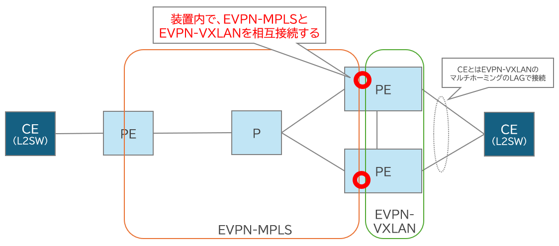
装置内に logical tunnel interface という内部のインターフェースを作って EVPN-MPLS と EVPN-VXLAN を相互接続をします。また、 logical tunnel interface に同じ ESI を設定することでEVPNマルチホーミングによる装置冗長も可能になります。
※自分で調べた内容をもとにまとめています。誤りが含まれている可能性がありますので、参考程度にご覧いただき、正確な情報は公式ドキュメント等をご確認ください!
EVPN-VXLAN と EVPN-MPLS を相互接続するメリット
こちらのサイトを ChatGPTさんに要約してもらうと
- EVPN-VXLANを実行するデータセンター(DC1/DC2)を、MPLSベースのEVPN WANを介して相互接続するソリューション
- 大規模なマルチテナントデータセンター環境において、高可用かつスケーラブルなDCI(Data Center Interconnect)を実現できる
とのことです。
また、ChatGPTさんによる EVPN-VXLAN と EVPN-MPLSの比較はざっくり以下の通りです
| 項目 | EVPN-VXLAN | EVPN-MPLS |
|---|---|---|
| メリット | - IP ファブリック上で容易にオーバーレイ展開 - ハードウェア非依存でクラウド環境とも親和性高い - マルチテナント分離が柔軟(VNI単位でVRF分離) |
- MPLS ネイティブのトラフィックエンジニアリング機能(TI-LFA, FRRなど)活用可 - UDP ヘッダオーバーヘッドなしで低レイテンシ |
| デメリット | - VXLAN ヘッダ(UDP+VNI)によるオーバーヘッド - マルチキャスト/ヘッドエンドフラッディング設定の手間 - 対応 ASIC要件が高い場合あり |
- MPLS ネットワーク構築・運用コストが高い - L2 オーバーレイに特化した柔軟性はやや劣る |
構成概要
今回は以下の構成をネットワークシミュレータで確認しました
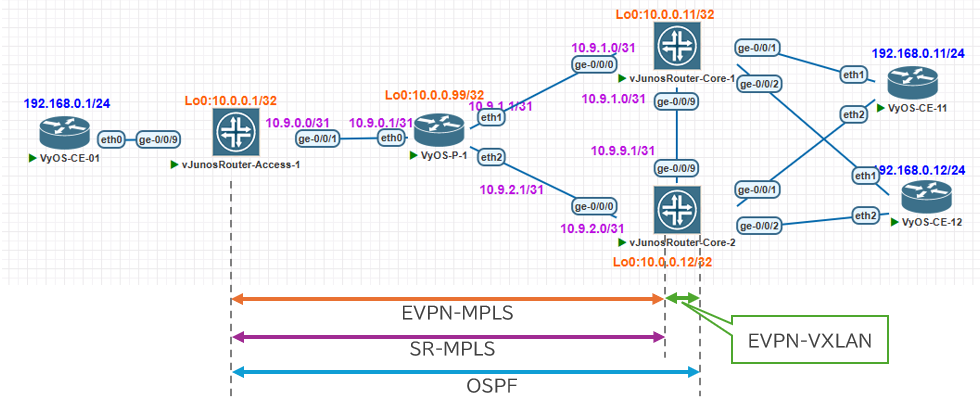
以下の機器を利用しています(どちらも現時点では無料で利用できます!)
- vJunos-Router : VPN を終端する PE ルータとして利用
- Version : 24.2R1-S2.5
- VyOS : CE ルーターや、途中の P ルーターとして利用
- Version: VyOS 1.5-rolling-202502190007
VPN のイメージは以下となります
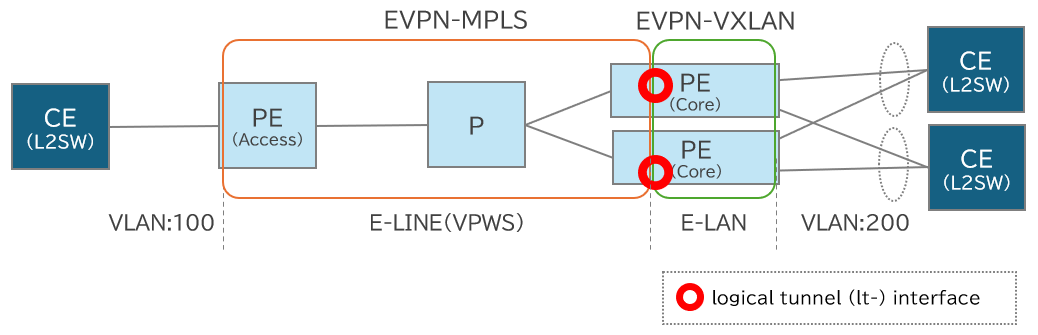
- CE と PEルーター間は VLAN Trunk
- PE(Access) ~ CE間は、VLAN-ID:100
- PE(Core) ~ CE間は、VLAN-ID:200
- PE(Access) と PE(Core) 間は、EVPN-MPLS の E-LINE を利用
- PE(Core) 側は、
- 装置内部に logical tunnel (lt-) interface を作って E-LINE の終端の IF とする
- EVPN マルチホーミングを利用した2台冗長
- PE(Core) 側は、
- PE(Core) のCE 側については、EVPN-VXLAN を利用
- こちらも logical tunnel (lt-) interface を入れる
- EVPNマルチホーミングを利用した2台冗長
- logical tunnel interface側とCE側それぞれ別のマルチホーミングで冗長
- E-LAN(MAC-VRF) を利用
- CE は2台準備して、アクセス側の CE から、コア側の2台の CE に対してマルチポイント接続させる
コンフィグ内容
各機器に設定したコンフィグは以下となります、簡単なコメントも記載してます。
vJunosRouter-Access-1
# ホストネーム設定
set system host-name vJunosRouter-Access-1

# IPアドレス設定
set interfaces ge-0/0/1 unit 0 family inet address 10.9.0.0/31
set interfaces lo0 unit 0 family inet address 10.0.0.1/32

# OSPF関連の設定、装置間のコストはすべて100にする
set routing-options router-id 10.0.0.1
set protocols ospf area 0.0.0.0 interface lo0.0 passive
set protocols ospf area 0.0.0.0 interface lo0.0 metric 10
set protocols ospf area 0.0.0.0 interface ge-0/0/1.0 interface-type p2p
set protocols ospf area 0.0.0.0 interface ge-0/0/1.0 metric 100


# SR-MPLSのSRGBを変更するために設定要
set chassis network-services enhanced-ip

# SR-MPLS関連の設定、各IFのMPLS有効と、SRGBの範囲(16000~24999)、Node-SID(16000+ipv4-index)の設定
set interfaces ge-0/0/1 unit 0 family mpls
set protocols mpls interface ge-0/0/1.0
set protocols ospf source-packet-routing node-segment ipv4-index 1
set protocols ospf source-packet-routing srgb start-label 16000
set protocols ospf source-packet-routing srgb index-range 8000

# EVPNのためのMP-BGPの設定、各PEルータとフルメッシュでBGP接続する
set routing-options autonomous-system 65000
set protocols bgp group MP_BGP_EVPN type internal
set protocols bgp group MP_BGP_EVPN local-address 10.0.0.1
set protocols bgp group MP_BGP_EVPN family evpn signaling
set protocols bgp group MP_BGP_EVPN neighbor 10.0.0.11
set protocols bgp group MP_BGP_EVPN neighbor 10.0.0.12

# CE側のIFの設定、VLAN:100で、E-LINE用のvlan-cccで設定する
set interfaces ge-0/0/9 flexible-vlan-tagging
set interfaces ge-0/0/9 encapsulation flexible-ethernet-services
set interfaces ge-0/0/9 unit 100 encapsulation vlan-ccc
set interfaces ge-0/0/9 unit 100 vlan-id 100

# E-LINEのVPN設定、evpn-vpwsで設定
set routing-instances EVPN_MPLS_E-LINE_100 instance-type evpn-vpws
set routing-instances EVPN_MPLS_E-LINE_100 protocols evpn interface ge-0/0/9.100 vpws-service-id local 100
set routing-instances EVPN_MPLS_E-LINE_100 protocols evpn interface ge-0/0/9.100 vpws-service-id remote 200
set routing-instances EVPN_MPLS_E-LINE_100 protocols evpn control-word
set routing-instances EVPN_MPLS_E-LINE_100 interface ge-0/0/9.100
set routing-instances EVPN_MPLS_E-LINE_100 route-distinguisher 10.0.0.1:100
set routing-instances EVPN_MPLS_E-LINE_100 vrf-target target:65000:100
vJunosRouter-Core-1
# ホストネーム設定
set system host-name vJunosRouter-Core-1

# 装置上で使用できるLAGの数を設定
set chassis aggregated-devices ethernet device-count 8

# IPアドレス設定
set interfaces ge-0/0/0 unit 0 family inet address 10.9.1.0/31
set interfaces ge-0/0/9 unit 0 family inet address 10.9.9.0/31
set interfaces lo0 unit 0 family inet address 10.0.0.11/32

# OSPF関連の設定、装置間のコストはすべて100にする
set routing-options router-id 10.0.0.11
set protocols ospf area 0.0.0.0 interface lo0.0 passive
set protocols ospf area 0.0.0.0 interface lo0.0 metric 10
set protocols ospf area 0.0.0.0 interface ge-0/0/0.0 interface-type p2p
set protocols ospf area 0.0.0.0 interface ge-0/0/0.0 metric 100
set protocols ospf area 0.0.0.0 interface ge-0/0/9.0 interface-type p2p
set protocols ospf area 0.0.0.0 interface ge-0/0/9.0 metric 100


# SR-MPLSのSRGBを変更するために設定要
set chassis network-services enhanced-ip

# SR-MPLS関連の設定、各IFのMPLS有効と、SRGBの範囲(16000~24999)、Node-SID(16000+ipv4-index)の設定
set interfaces ge-0/0/0 unit 0 family mpls
set interfaces ge-0/0/9 unit 0 family mpls
set protocols mpls interface ge-0/0/0.0
set protocols mpls interface ge-0/0/9.0
set protocols ospf source-packet-routing node-segment ipv4-index 11
set protocols ospf source-packet-routing srgb start-label 16000
set protocols ospf source-packet-routing srgb index-range 8000

# EVPNのためのMP-BGPの設定、各PEルータとフルメッシュでBGP接続する
set routing-options autonomous-system 65000
set protocols bgp group MP_BGP_EVPN type internal
set protocols bgp group MP_BGP_EVPN local-address 10.0.0.11
set protocols bgp group MP_BGP_EVPN family evpn signaling
set protocols bgp group MP_BGP_EVPN neighbor 10.0.0.1
set protocols bgp group MP_BGP_EVPN neighbor 10.0.0.12

# EVPN-MPLSとEVPN-VXLANを装置内で相互接続させるための logical tunnel interfaceの設定、lt-0/0 を使用できるようにする
set chassis fpc 0 pic 0 tunnel-services

# lt-0/0/0.1をEVPN-MPLSのE-LINEの終端インターフェースとして設定
set interfaces lt-0/0/0 unit 1 encapsulation vlan-ccc
set interfaces lt-0/0/0 unit 1 vlan-id 100

# lt-0/0/0.2をEVPN-VXLAN側のインターフェースとして設定
set interfaces lt-0/0/0 unit 2 encapsulation vlan-bridge
set interfaces lt-0/0/0 unit 2 vlan-id 100

# lt-0/0/0.1とlt-0/0/0.2がペアとして相互接続設定
set interfaces lt-0/0/0 unit 1 peer-unit 2
set interfaces lt-0/0/0 unit 2 peer-unit 1

# lt-0/0/0は2台でall-activeのEVPNマルチホーミングで冗長させるESI設定、ESIは2台で共通の値
set interfaces lt-0/0/0 esi 00:55:55:55:55:55:55:00:00:00
set interfaces lt-0/0/0 esi all-active

# EVPN-MPLSのE-LINEのVPN設定、evpn-vpwsで設定、IFはlt-0/0/0.1で設定
set routing-instances EVPN_MPLS_E-LINE_100 instance-type evpn-vpws
set routing-instances EVPN_MPLS_E-LINE_100 protocols evpn interface lt-0/0/0.1 vpws-service-id local 200
set routing-instances EVPN_MPLS_E-LINE_100 protocols evpn interface lt-0/0/0.1 vpws-service-id remote 100
set routing-instances EVPN_MPLS_E-LINE_100 protocols evpn control-word
set routing-instances EVPN_MPLS_E-LINE_100 interface lt-0/0/0.1
set routing-instances EVPN_MPLS_E-LINE_100 route-distinguisher 10.0.0.11:100
set routing-instances EVPN_MPLS_E-LINE_100 vrf-target target:65000:100


# VXLANで使用するCE-11側のIFの設定、ae1でLACP:slowのLAGの設定、2台でLACPのsystem-idを合わせる
set interfaces ge-0/0/1 gigether-options 802.3ad ae1
set interfaces ae1 aggregated-ether-options lacp active
set interfaces ae1 aggregated-ether-options lacp periodic slow
set interfaces ae1 aggregated-ether-options lacp system-id 00:01:01:01:01:01

# CE-11側のLAGでEVPNマルチホーミングで冗長させるESI設定、ESIは2台で共通の値でlt-0/0/0とは別の値を設定
set interfaces ae1 esi 00:11:11:11:11:11:11:00:00:00
set interfaces ae1 esi all-active

# CE-11側のLAGのVLAN設定VLAN:200で設定
set interfaces ae1 flexible-vlan-tagging
set interfaces ae1 encapsulation flexible-ethernet-services
set interfaces ae1 unit 200 encapsulation vlan-bridge
set interfaces ae1 unit 200 vlan-id 200

# VXLANで使用するCE-12側のIFの設定、ae2でLACP:slowのLAGの設定、2台でLACPのsystem-idを合わせる
set interfaces ge-0/0/2 gigether-options 802.3ad ae2
set interfaces ae2 aggregated-ether-options lacp active
set interfaces ae2 aggregated-ether-options lacp periodic slow
set interfaces ae2 aggregated-ether-options lacp system-id 00:02:02:02:02:02

# CE-12側のLAGでEVPNマルチホーミングで冗長させるESI設定、ESIは2台で共通の値でlt-0/0/0とは別の値を設定
set interfaces ae2 esi 00:22:22:22:22:22:22:00:00:00
set interfaces ae2 esi all-active

# CE-12側のLAGのVLAN設定VLAN:200で設定
set interfaces ae2 flexible-vlan-tagging
set interfaces ae2 encapsulation flexible-ethernet-services
set interfaces ae2 unit 200 encapsulation vlan-bridge
set interfaces ae2 unit 200 vlan-id 200

# EVPN-VXLANのMAC-VRFのVPN設定、IFはlt-0/0/0.2とLAGのIFで設定
set routing-instances EVPN_VXLAN_200 instance-type mac-vrf
set routing-instances EVPN_VXLAN_200 protocols evpn encapsulation vxlan
set routing-instances EVPN_VXLAN_200 vtep-source-interface lo0.0
set routing-instances EVPN_VXLAN_200 bridge-domains BRIDGE_200 vlan-id 100
set routing-instances EVPN_VXLAN_200 bridge-domains BRIDGE_200 interface ae1.200
set routing-instances EVPN_VXLAN_200 bridge-domains BRIDGE_200 interface ae2.200
set routing-instances EVPN_VXLAN_200 bridge-domains BRIDGE_200 interface lt-0/0/0.2
set routing-instances EVPN_VXLAN_200 bridge-domains BRIDGE_200 vxlan vni 200
set routing-instances EVPN_VXLAN_200 service-type vlan-based
set routing-instances EVPN_VXLAN_200 route-distinguisher 10.0.0.11:200
set routing-instances EVPN_VXLAN_200 vrf-target target:65000:200
vJunosRouter-Core-2
# ホストネーム設定
set system host-name vJunosRouter-Core-2

# 装置上で使用できるLAGの数を設定
set chassis aggregated-devices ethernet device-count 8

# IPアドレス設定
set interfaces ge-0/0/0 unit 0 family inet address 10.9.2.0/31
set interfaces ge-0/0/9 unit 0 family inet address 10.9.9.1/31
set interfaces lo0 unit 0 family inet address 10.0.0.12/32

# OSPF関連の設定、装置間のコストはすべて100にする
set routing-options router-id 10.0.0.12
set protocols ospf area 0.0.0.0 interface lo0.0 passive
set protocols ospf area 0.0.0.0 interface lo0.0 metric 10
set protocols ospf area 0.0.0.0 interface ge-0/0/0.0 interface-type p2p
set protocols ospf area 0.0.0.0 interface ge-0/0/0.0 metric 100
set protocols ospf area 0.0.0.0 interface ge-0/0/9.0 interface-type p2p
set protocols ospf area 0.0.0.0 interface ge-0/0/9.0 metric 100


# SR-MPLSのSRGBを変更するために設定要
set chassis network-services enhanced-ip

# SR-MPLS関連の設定、各IFのMPLS有効と、SRGBの範囲(16000~24999)、Node-SID(16000+ipv4-index)の設定
set interfaces ge-0/0/0 unit 0 family mpls
set interfaces ge-0/0/9 unit 0 family mpls
set protocols mpls interface ge-0/0/0.0
set protocols mpls interface ge-0/0/9.0
set protocols ospf source-packet-routing node-segment ipv4-index 12
set protocols ospf source-packet-routing srgb start-label 16000
set protocols ospf source-packet-routing srgb index-range 8000

# EVPNのためのMP-BGPの設定、各PEルータとフルメッシュでBGP接続する
set routing-options autonomous-system 65000
set protocols bgp group MP_BGP_EVPN type internal
set protocols bgp group MP_BGP_EVPN local-address 10.0.0.12
set protocols bgp group MP_BGP_EVPN family evpn signaling
set protocols bgp group MP_BGP_EVPN neighbor 10.0.0.1
set protocols bgp group MP_BGP_EVPN neighbor 10.0.0.11

# EVPN-MPLSとEVPN-VXLANを装置内で相互接続させるための logical tunnel interfaceの設定、lt-0/0 を使用できるようにする
set chassis fpc 0 pic 0 tunnel-services

# lt-0/0/0.1をEVPN-MPLSのE-LINEの終端インターフェースとして設定
set interfaces lt-0/0/0 unit 1 encapsulation vlan-ccc
set interfaces lt-0/0/0 unit 1 vlan-id 100

# lt-0/0/0.2をEVPN-VXLAN側のインターフェースとして設定
set interfaces lt-0/0/0 unit 2 encapsulation vlan-bridge
set interfaces lt-0/0/0 unit 2 vlan-id 100

# lt-0/0/0.1とlt-0/0/0.2がペアとして相互接続設定
set interfaces lt-0/0/0 unit 1 peer-unit 2
set interfaces lt-0/0/0 unit 2 peer-unit 1

# lt-0/0/0は2台でall-activeのEVPNマルチホーミングで冗長させるESI設定、ESIは2台で共通の値
set interfaces lt-0/0/0 esi 00:55:55:55:55:55:55:00:00:00
set interfaces lt-0/0/0 esi all-active

# EVPN-MPLSのE-LINEのVPN設定、evpn-vpwsで設定、IFはlt-0/0/0.1で設定
set routing-instances EVPN_MPLS_E-LINE_100 instance-type evpn-vpws
set routing-instances EVPN_MPLS_E-LINE_100 protocols evpn interface lt-0/0/0.1 vpws-service-id local 200
set routing-instances EVPN_MPLS_E-LINE_100 protocols evpn interface lt-0/0/0.1 vpws-service-id remote 100
set routing-instances EVPN_MPLS_E-LINE_100 protocols evpn control-word
set routing-instances EVPN_MPLS_E-LINE_100 interface lt-0/0/0.1
set routing-instances EVPN_MPLS_E-LINE_100 route-distinguisher 10.0.0.12:100
set routing-instances EVPN_MPLS_E-LINE_100 vrf-target target:65000:100


# VXLANで使用するCE-11側のIFの設定、ae1でLACP:slowのLAGの設定、2台でLACPのsystem-idを合わせる
set interfaces ge-0/0/1 gigether-options 802.3ad ae1
set interfaces ae1 aggregated-ether-options lacp active
set interfaces ae1 aggregated-ether-options lacp periodic slow
set interfaces ae1 aggregated-ether-options lacp system-id 00:01:01:01:01:01

# CE-11側のLAGでEVPNマルチホーミングで冗長させるESI設定、ESIは2台で共通の値でlt-0/0/0とは別の値を設定
set interfaces ae1 esi 00:11:11:11:11:11:11:00:00:00
set interfaces ae1 esi all-active

# CE-11側のLAGのVLAN設定VLAN:200で設定
set interfaces ae1 flexible-vlan-tagging
set interfaces ae1 encapsulation flexible-ethernet-services
set interfaces ae1 unit 200 encapsulation vlan-bridge
set interfaces ae1 unit 200 vlan-id 200

# VXLANで使用するCE-12側のIFの設定、ae2でLACP:slowのLAGの設定、2台でLACPのsystem-idを合わせる
set interfaces ge-0/0/2 gigether-options 802.3ad ae2
set interfaces ae2 aggregated-ether-options lacp active
set interfaces ae2 aggregated-ether-options lacp periodic slow
set interfaces ae2 aggregated-ether-options lacp system-id 00:02:02:02:02:02

# CE-12側のLAGでEVPNマルチホーミングで冗長させるESI設定、ESIは2台で共通の値でlt-0/0/0とは別の値を設定
set interfaces ae2 esi 00:22:22:22:22:22:22:00:00:00
set interfaces ae2 esi all-active

# CE-12側のLAGのVLAN設定VLAN:200で設定
set interfaces ae2 flexible-vlan-tagging
set interfaces ae2 encapsulation flexible-ethernet-services
set interfaces ae2 unit 200 encapsulation vlan-bridge
set interfaces ae2 unit 200 vlan-id 200

# EVPN-VXLANのMAC-VRFのVPN設定、IFはlt-0/0/0.2とLAGのIFで設定
set routing-instances EVPN_VXLAN_200 instance-type mac-vrf
set routing-instances EVPN_VXLAN_200 protocols evpn encapsulation vxlan
set routing-instances EVPN_VXLAN_200 vtep-source-interface lo0.0
set routing-instances EVPN_VXLAN_200 bridge-domains BRIDGE_200 vlan-id 100
set routing-instances EVPN_VXLAN_200 bridge-domains BRIDGE_200 interface ae1.200
set routing-instances EVPN_VXLAN_200 bridge-domains BRIDGE_200 interface ae2.200
set routing-instances EVPN_VXLAN_200 bridge-domains BRIDGE_200 interface lt-0/0/0.2
set routing-instances EVPN_VXLAN_200 bridge-domains BRIDGE_200 vxlan vni 200
set routing-instances EVPN_VXLAN_200 service-type vlan-based
set routing-instances EVPN_VXLAN_200 route-distinguisher 10.0.0.12:200
set routing-instances EVPN_VXLAN_200 vrf-target target:65000:200
VyOS-P-1
# ホストネーム設定
set system host-name 'VyOS-P-1'

# IPアドレス設定
set interfaces ethernet eth0 address '10.9.0.1/31'
set interfaces ethernet eth1 address '10.9.1.1/31'
set interfaces ethernet eth2 address '10.9.2.1/31'
set interfaces loopback lo address '10.0.0.99/32'

# SR-MPLSの各ルータ向けインターフェースでMPLS設定
set protocols mpls interface 'eth0'
set protocols mpls interface 'eth1'
set protocols mpls interface 'eth2'

# OSPF関連の設定、装置間のコストはすべて100にする
set protocols ospf parameters router-id '10.0.0.99'
set protocols ospf interface eth0 area '0.0.0.0'
set protocols ospf interface eth0 cost '100'
set protocols ospf interface eth0 network 'point-to-point'
set protocols ospf interface eth1 area '0.0.0.0'
set protocols ospf interface eth1 cost '100'
set protocols ospf interface eth1 network 'point-to-point'
set protocols ospf interface eth2 area '0.0.0.0'
set protocols ospf interface eth2 cost '100'
set protocols ospf interface eth2 network 'point-to-point'
set protocols ospf interface lo area '0.0.0.0'
set protocols ospf interface lo passive

# SR-MPLSで利用するopaque-lsaを有効化
set protocols ospf parameters opaque-lsa

# SR-MPLS関連の設定、SRGBの範囲(16000~24999)、Node-SID(16000+index)の設定
set protocols ospf segment-routing global-block high-label-value '24999'
set protocols ospf segment-routing global-block low-label-value '16000'
set protocols ospf segment-routing prefix 10.0.0.99/32 index explicit-null
set protocols ospf segment-routing prefix 10.0.0.99/32 index value '99'
VyOS-CE-01
# ホストネーム設定
set system host-name 'VyOS-CE-01'

# VLAN:100にIP設定
set interfaces ethernet eth0 vif 100 address '192.168.0.1/24'
VyOS-CE-11
# ホストネーム設定
set system host-name 'VyOS-CE-11'

# LAGの設定、LACP:slowで設定
set interfaces bonding bond0 hash-policy 'layer2'
set interfaces bonding bond0 lacp-rate 'slow'
set interfaces bonding bond0 mac '00:00:00:00:99:11'
set interfaces bonding bond0 member interface 'eth1'
set interfaces bonding bond0 member interface 'eth2'
set interfaces bonding bond0 mode '802.3ad'
set interfaces bonding bond0 system-mac '00:00:00:00:99:11'

# VLAN:200にIP設定
set interfaces bonding bond0 vif 200 address '192.168.0.11/24'
VyOS-CE-11
# ホストネーム設定
set system host-name 'VyOS-CE-12'

# LAGの設定、LACP:slowで設定
set interfaces bonding bond0 hash-policy 'layer2'
set interfaces bonding bond0 lacp-rate 'slow'
set interfaces bonding bond0 mac '00:00:00:00:99:22'
set interfaces bonding bond0 member interface 'eth1'
set interfaces bonding bond0 member interface 'eth2'
set interfaces bonding bond0 mode '802.3ad'
set interfaces bonding bond0 system-mac '00:00:00:00:99:22'

# VLAN:200にIP設定
set interfaces bonding bond0 vif 200 address '192.168.0.12/24'
相互接続部分の設定について
EVPN-MPLS と EVPN-VXLAN の相互接続部分のコンフィグだけ抜粋しまて説明します。その他コンフィグは上記の全コンフィグのコメントを参考にしてください。
設定イメージは以下のようなイメージになります。

設定については、以下の設定で logical tunnel interface を設定することで相互接続し、さらにEVPNマルチホーミングで装置冗長が可能になります。
- logical tunnel interface の
lt-0/0を使用できるようにする - サブIFとしてEVPN-MPLS用とEVPN-VXLAN用の設定
-
lt-0/0/0.1とlt-0/0/0.2がペアとして相互接続設定 -
lt-0/0/0を all-active のEVPNマルチホーミングで冗長させるESI設定
# 1. EVPN-MPLSとEVPN-VXLANを装置内で相互接続させるための logical tunnel interfaceの設定、lt-0/0 を使用できるようにする
set chassis fpc 0 pic 0 tunnel-services

# 2. lt-0/0/0.1(EVPN-MPLS用)とlt-0/0/0.2(EVPN-VXLAN用)を設定
set interfaces lt-0/0/0 unit 1 encapsulation vlan-ccc
set interfaces lt-0/0/0 unit 1 vlan-id 100

set interfaces lt-0/0/0 unit 2 encapsulation vlan-bridge
set interfaces lt-0/0/0 unit 2 vlan-id 100

# 3. lt-0/0/0.1とlt-0/0/0.2がペアとして相互接続設定
set interfaces lt-0/0/0 unit 1 peer-unit 2
set interfaces lt-0/0/0 unit 2 peer-unit 1

# 4. lt-0/0/0は2台でall-activeのEVPNマルチホーミングで冗長させるESI設定、ESIは2台で共通の値
set interfaces lt-0/0/0 esi 00:55:55:55:55:55:55:00:00:00
set interfaces lt-0/0/0 esi all-active
動作確認
コンフィグをいれたあとですが、自分の環境だと JunosRouter と VyOS でそれぞれ以下の実施しないと正常に動作しなかったので記載しておきます
- vJunosRouter :
request system rebootで一度再起動させる - VyOS : SR-MPLS の Node-SID をOSPFで学習しなかったので、
restart ospfで OSPF のプロセス再起動実施- ただしく動作していれば
show mpls tableで他の機器の Node-SID ( 16001 など) を学習します
- ただしく動作していれば
EVPN-MPLS での E-LINE の状態確認
show evpn vpws-instanceで確認すると以下の通り期待通り動作していることが確認
- vJunosRouter-Access-1 : Remote 側が
10.0.0.11(Core-1) と10.0.0.12(Core-2) で all-active で動作 - JunosRouter-Core-1 : Local 側に
10.0.0.12(Core-2) が自身と all-active で、Remote 側が10.0.0.1(Access-1) で single-home で確認
root@vJunosRouter-Access-1> show evpn vpws-instance
Instance: EVPN_MPLS_E-LINE_100, Instance type: EVPN VPWS, Encapsulation type: MPLS
  Route Distinguisher: 10.0.0.1:100
  Number of local interfaces: 1 (1 up)

    Interface name  ESI                            Mode          Role       Status     Control-Word    Flow-Label-Tx    Flow-Label-Rx
    ge-0/0/9.100    00:00:00:00:00:00:00:00:00:00 single-homed    Primary    Up         Yes             No               No
        Local SID: 100 Advertised Label: 16
        Remote SID: 200
            PE addr         ESI                           Label  End.Dx2 SID     Mode           Role     TS                      Status
            10.0.0.11       00:55:55:55:55:55:55:00:00:00 16                     all-active     Primary  2025-06-xx xx:xx:27.941 Resolved
            10.0.0.12       00:55:55:55:55:55:55:00:00:00 16                     all-active     Primary  2025-06-xx xx:xx:10.722 Resolved
  Number of protect interfaces: 0

    Fast Convergence Information
    ESI: 00:55:55:55:55:55:55:00:00:00 Number of PE nodes: 2
        PE: 10.0.0.11
            Advertised SID: 200
        PE: 10.0.0.12
            Advertised SID: 200
root@vJunosRouter-Core-1> show evpn vpws-instance
Instance: EVPN_MPLS_E-LINE_100, Instance type: EVPN VPWS, Encapsulation type: MPLS
  Route Distinguisher: 10.0.0.11:100
  Number of local interfaces: 1 (1 up)

    Interface name  ESI                            Mode          Role       Status     Control-Word    Flow-Label-Tx    Flow-Label-Rx
    lt-0/0/0.1      00:55:55:55:55:55:55:00:00:00 all-active      Primary    Up         Yes             No               No
        Local SID: 200 Advertised Label: 16
            PE addr         ESI                           Label  End.Dx2 SID     Mode           Role     TS                      Status
            10.0.0.12       00:55:55:55:55:55:55:00:00:00 16                     all-active     Primary  2025-06-xx xx:xx:00.244 Resolved
        Remote SID: 100
            PE addr         ESI                           Label  End.Dx2 SID     Mode           Role     TS                      Status
            10.0.0.1        00:00:00:00:00:00:00:00:00:00 16                     single-homed   Primary  2025-06-xx xx:xx:15.719 Resolved
  Number of protect interfaces: 0

    Fast Convergence Information
    ESI: 00:55:55:55:55:55:55:00:00:00 Number of PE nodes: 1
        PE: 10.0.0.12
            Advertised SID: 200
EVPN-VXLAN での状態確認
VXLAN側も show evpn instance EVPN_VXLAN_200 extensive で確認すると以下の通り期待通り動作していることが確認
- VXLAN で利用したい各インターフェース
ae1.200ae2.200lt-0/0/0.2がそれぞれ、10.0.0.12(Core-2) と all-active で動作していることを確認
root@vJunosRouter-Core-1> show evpn instance EVPN_VXLAN_200 extensive
Instance: EVPN_VXLAN_200
  Route Distinguisher: 10.0.0.11:200
  VLAN ID: 100
  Encapsulation type: VXLAN    <---- # Encapsulation が VXLAN
        :
    VLAN  Domain-ID Intfs/up   IRB-intf  Mode            MAC-sync v4-SG-sync v6-SG-sync
    100   200          3  3              Extended        Enabled  Disabled   Disabled
  Number of neighbors: 1
    Address               MAC    MAC+IP        AD        IM        ES Leaf-label DCI-Peer Flow-label DT2U-SID           DT2M-SID
    10.0.0.12               0         0         6         1         0                           NO
  Number of ethernet segments: 3
    ESI: 00:11:11:11:11:11:11:00:00:00
      Status: Resolved by IFL ae1.200    <---- # CE-11向けのLAGがESIに入っている
        :
      Number of remote PEs connected: 1
        Remote-PE        MAC-label  Aliasing-label  Mode
        10.0.0.12        0          200             all-active    <---- # Core-02 と all-activeで冗長できてる
        :
    ESI: 00:22:22:22:22:22:22:00:00:00
      Status: Resolved by IFL ae2.200    <---- # CE-12向けのLAGがESIに入っている
        :
      Number of remote PEs connected: 1
        Remote-PE        MAC-label  Aliasing-label  Mode
        10.0.0.12        0          200             all-active    <---- # Core-02 と all-activeで冗長できてる
        :
    ESI: 00:55:55:55:55:55:55:00:00:00
      Status: Resolved by IFL lt-0/0/0.2    <---- # EVPN-MPLSのE-LINE用IFがESIに入っている
        :
      Number of remote PEs connected: 1
        Remote-PE        MAC-label  Aliasing-label  Mode
        10.0.0.12        0          200             all-active    <---- # Core-02 と all-activeで冗長できてる
        :
PING疎通確認
CE の VyOS 間でPING疎通するか確認する
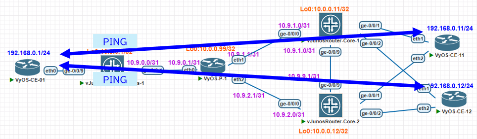
以下の通り PING 疎通することを確認
vyos@VyOS-CE-01:~$ ping 192.168.0.11
PING 192.168.0.11 (192.168.0.11) 56(84) bytes of data.
64 bytes from 192.168.0.11: icmp_seq=1 ttl=64 time=3.98 ms
64 bytes from 192.168.0.11: icmp_seq=2 ttl=64 time=2.73 ms
^C
--- 192.168.0.11 ping statistics ---
2 packets transmitted, 2 received, 0% packet loss, time 1001ms
rtt min/avg/max/mdev = 2.726/3.353/3.981/0.627 ms
vyos@VyOS-CE-01:~$ ping 192.168.0.12
PING 192.168.0.12 (192.168.0.12) 56(84) bytes of data.
64 bytes from 192.168.0.12: icmp_seq=1 ttl=64 time=7.37 ms
64 bytes from 192.168.0.12: icmp_seq=2 ttl=64 time=2.92 ms
^C
--- 192.168.0.12 ping statistics ---
2 packets transmitted, 2 received, 0% packet loss, time 1002ms
rtt min/avg/max/mdev = 2.918/5.145/7.372/2.227 ms
vyos@VyOS-CE-01:~$
MACアドレス学習を確認
Core側で show bridge mac-table の確認をすると以下の通り、期待してる動作をしていることが確認できます
- VXLAN 側のインスタンスでMACアドレス学習している
- 2台の Core でMACアドレスが同期できている
root@vJunosRouter-Core-1> show bridge mac-table

MAC flags       (S -static MAC, D -dynamic MAC, L -locally learned, C -Control MAC
    O -OVSDB MAC, SE -Statistics enabled, NM -Non configured MAC, R -Remote PE MAC, P -Pinned MAC)

Routing instance : EVPN_VXLAN_200
 Bridging domain : BRIDGE_200, VLAN : 100
   MAC                 MAC      GBP     Logical                Active
   address             flags    TAG     interface              source
   00:00:00:00:99:11   DLR              ae1.200
   00:00:00:00:99:12   DLR              ae2.200
   50:62:e3:00:32:00   DLR              lt-0/0/0.2
root@vJunosRouter-Core-2> show bridge mac-table

MAC flags       (S -static MAC, D -dynamic MAC, L -locally learned, C -Control MAC
    O -OVSDB MAC, SE -Statistics enabled, NM -Non configured MAC, R -Remote PE MAC, P -Pinned MAC)

Routing instance : EVPN_VXLAN_200
 Bridging domain : BRIDGE_200, VLAN : 100
   MAC                 MAC      GBP     Logical                Active
   address             flags    TAG     interface              source
   00:00:00:00:99:11   DLR              ae1.200
   00:00:00:00:99:12   DLR              ae2.200
   50:62:e3:00:32:00   DLR              lt-0/0/0.2
参考ですが、Access-1 側は E-LINE のためMACアドレスは学習しない状態となります
root@vJunosRouter-Access-1> show bridge mac-table

root@vJunosRouter-Access-1>
冗長部分の切り替わり動作確認
最後に、all-activeで冗長してる部分を一部停止させてみた際の通信状態を確認します
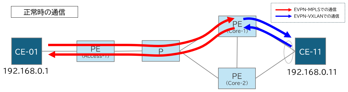
まず、正常時には以下のようなPING通信であることを確認します
( Core-1 と Core-2 のどちらをとおるかはフローによっては変わるため、必ず Core-1 をとおるわけではないです)
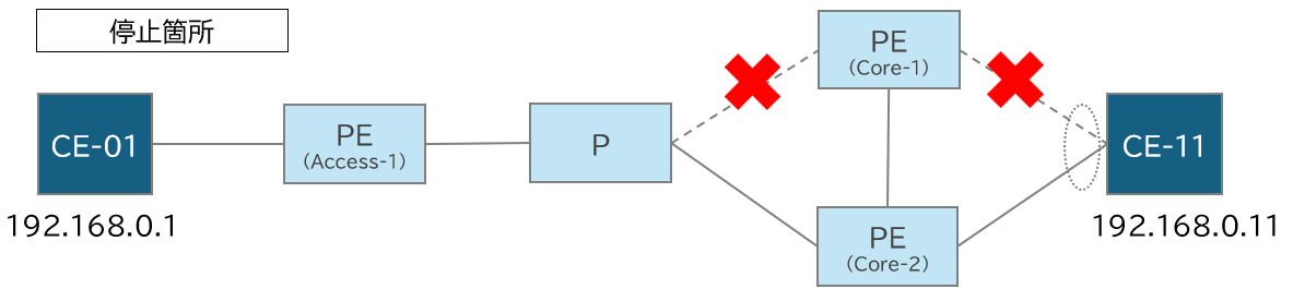
この状態で以下のように Core-1 の 2箇所を停止させます
この状態で、PINGの疎通が通ることを確認と、どういった経路にいってるか確認したところ以下の通りでした
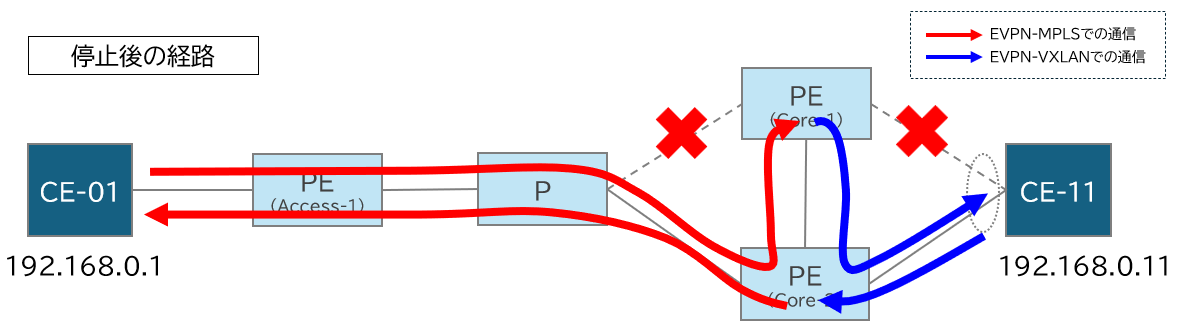
行き( CE-01 → CE-11 )と帰り( CE-11 → CE-01 )が違う経路でした、以下の動作を想定してます
- 行きのEVPN-MPLS 通信は、停止前も後の Core-01 の Node-SID を終端点として向かうことは変わらず、SR-MPLS区間で Core-01 の Node-SID への向かい方が、Core-02 経由の経路に変わった
- その後、CE-11に行くためには EVPN-VXLAN の通信として Core-02 を一度迂回して CE-11 へ行く
- 帰りについては、Core-02からそのまま、EVPN-MPLSの通信として、Access-1 に向かう
停止させても、行きの Core-01 の Node-SID を終端点として向かうことは変わらない部分が肝だと思います
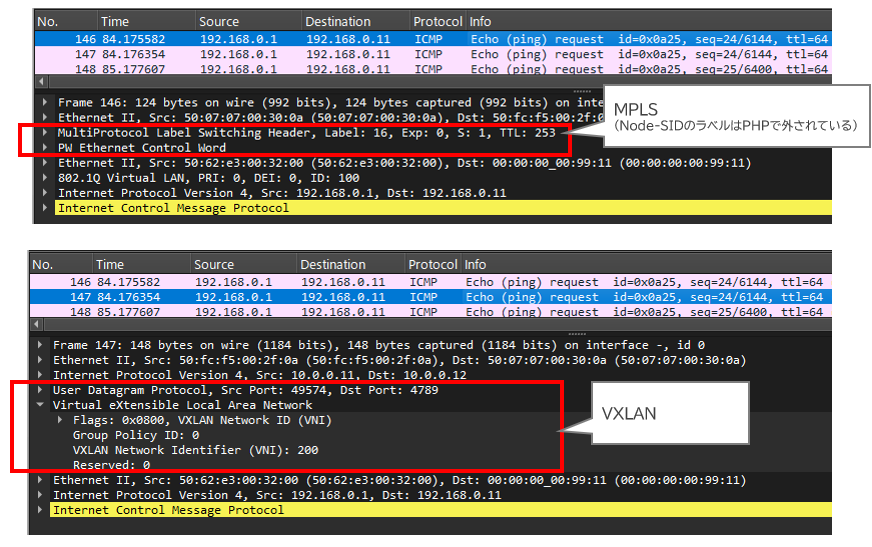
実際に Core-01 と Core-02 間でパケットキャプチャをすると Core-01 に MPLS で入ったあとに VXLAN で戻していることが確認できます
最後に
EVPN-MPLS と VXLAN の相互接続や冗長化構成を vJunos-Router で動作確認し、柔軟な接続が可能であることを確認できました。
EVPN-MPLS の E-LINE だと、MACアドレス学習がなくなり装置の負荷は減りますが、PE と CE 間の接続が、ポイント・ツー・ポイント接続に限定されてしまうことがデメリットになります。
今回のように上位側は 1台の装置内で VXLAN と組み合わせることで、Access側はMACアドレス学習の負荷を下げつつ、マルチポイント接続させることができました。
(かわりにCore側は負担が大きいかもです)