冗長構成を組む際、現場で広く利用される技術のひとつに LACP があります。
LACP は 標準化されたプロトコルであり、既存環境でも Cisco 同士、あるいは Cisco と他ベンダー機器との間で動作している構成を見る機会は多いのではないでしょうか。
一方で、そうした構成はあくまで「すでに動いている状態」を目にしているに過ぎず、実際にマルチベンダー環境で LACP を設計・構築し、挙動まで検証した経験があるケースは、それほど多くないのが実情だと思われます。
また、実際の現場では単一ベンダーでネットワークが完結することは少なく、Ciscoと複数ベンダーを組み合わせた構成は一般的に存在します。このようなマルチベンダー環境では、LACP のような標準技術を用いることで接続自体は成立しますが、どのように通信が成立するのかといった挙動を事前に把握しておかなければ、実運用におけるリスクとなります。
本記事では、Cisco機器と他ベンダーのFW機器でLACPを組み合わせたマルチベンダー構成を題材に、単一リンク断時の通信継続や MAC アドレスの学習先の変化に着目しながら、L2 レイヤにおける冗長動作が実際にどのように振る舞うのかを、検証ベースで整理していきます。
検証①
検証構成
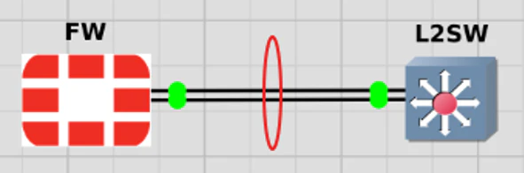
FWとL2SW間において、LACPによるポートチャネルを構成する。
設定内容
設定内容
config system interface
    edit agg_l2sw
        set vdom root
        set type aggregate
        set member port2 port3
        set lacp-mode active
        set role lan
    next
end
interface range Gi0/0-1
 channel-group 10 mode active
!
interface Port-channel10
no shutdown
結果
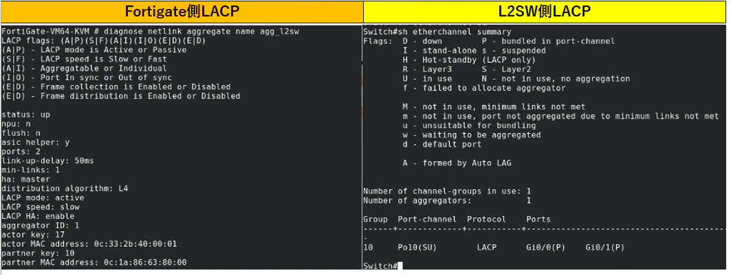
Cisco L2スイッチと FW間で LACP によるポートチャネルは問題なく形成され、マルチベンダー環境でも基本的な接続は成立することを確認できた。
次はこの構成をベースに、vPC を含めた冗長構成へ拡張し、実際の挙動を見ていく。
検証②
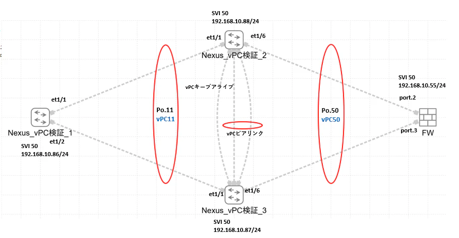
第31回 Nexus vPC 構成と検証で作成した構成をベースとし、本検証では一部変更している。前回はCiscoのルータを対向とした構成で検証を行ったが、今回は対向機器をFWに変更し、LACPのマルチベンダー環境における挙動を確認する。
検証構成
使用機器およびOS
本検証は、仮想環境(GNS3)上にて構築し、以下の機器およびOSを使用
Nexus_vPC検証➀~➂
Nexus 9000v(N9Kv)
FW
FortiGate VM
FortiOS 7.2 系
設定内容
設定内容
feature lacp
feature interface-vlan

vlan 50

interface Port-channel11
switchport mode trunk
switchport trunk allowed vlan 50
no shutdown

interface ethernet 1/1
switchport mode trunk
switchport trunk allowed vlan 50
channel-group 11 mode active

interface ethernet 1/2
switchport mode trunk
switchport trunk allowed vlan 50
channel-group 11 mode active

int vlan 50
ip address 192.168.10.86 255.255.255.0
feature interface-vlan
feature lacp
feature vpc
feature hsrp

vlan 50

interface mgmt0
vrf member management
ip address 10.199.199.101/24

vpc domain 1
peer-keepalive destination 10.199.199.102 source 10.199.199.101 vrf management
peer-gateway
peer-switch
auto-recovery
delay restore 150


spanning-tree vlan 50 priority 4096

interface port-channel 1
switchport mode trunk
switchport trunk allowed vlan 50
spanning-tree port type network
vpc peer-link


interface port-channel 11
switchport mode trunk
switchport trunk allowed vlan 50
spanning-tree port type edge
vpc 11

interface Ethernet1/1
switchport mode trunk
switchport trunk allowed vlan 50
channel-group 11 mode active


interface Ethernet1/4
switchport mode trunk
switchport trunk allowed vlan 50
channel-group 1 mode active

interface Ethernet1/5
switchport mode trunk
switchport trunk allowed vlan 50
channel-group 1 mode active

interface port-channel 50
switchport mode trunk
switchport trunk allowed vlan 50
vpc 50


interface ethernet1/6
switchport mode trunk
switchport trunk allowed vlan 50
channel-group 50 mode active

int vlan 50
ip address 192.168.10.88 255.255.255.0
feature interface-vlan
feature lacp
feature vpc
feature hsrp

vlan 50

interface mgmt0
vrf member management
ip address 10.199.199.102/24

vpc domain 1
peer-keepalive destination 10.199.199.101 source 10.199.199.102 vrf management
peer-gateway
peer-switch
auto-recovery
delay restore 150


spanning-tree vlan 50 priority 4096

interface port-channel 1
switchport mode trunk
switchport trunk allowed vlan 50
spanning-tree port type network
vpc peer-link


interface port-channel 11
switchport mode trunk
switchport trunk allowed vlan 50
spanning-tree port type edge
vpc 11

interface Ethernet1/1
switchport mode trunk
switchport trunk allowed vlan 50
channel-group 11 mode active


interface Ethernet1/4
switchport mode trunk
switchport trunk allowed vlan 50
channel-group 1 mode active

interface Ethernet1/5
switchport mode trunk
switchport trunk allowed vlan 50
channel-group 1 mode active

interface port-channel 50
switchport mode trunk
switchport trunk allowed vlan 50
vpc 50


interface ethernet1/6
switchport mode trunk
switchport trunk allowed vlan 50
channel-group 50 mode active

int vlan 50
ip address 192.168.10.87 255.255.255.0
config system interface
    edit agg_l2sw
        set vdom root
        set type aggregate
        set member port2 port3
        set lacp-mode active
        set role lan
    next
    edit vlan50
        set vdom root
        set interface agg_l2sw
        set vlanid 50
        set ip 192.168.10.55 255.255.255.0
        set allowaccess ping https ssh
    next
end
各種検証
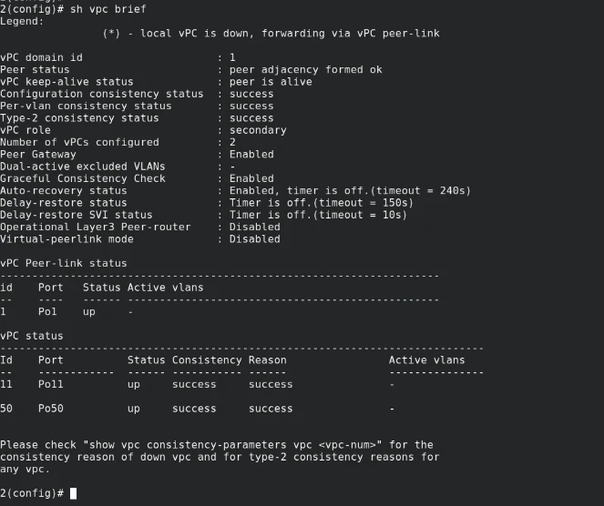
検証前確認
LACPが全て設立できていることを確認。
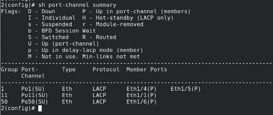
vPCが全てアップしていることを確認
検証①:疎通確認(到達性確認)
各Nexus(vPC検証_1~3)のSVIに設定したアドレスとFW間で双方向の疎通確認を実施。
その結果、すべてのノード間で正常に通信が可能であることを確認。
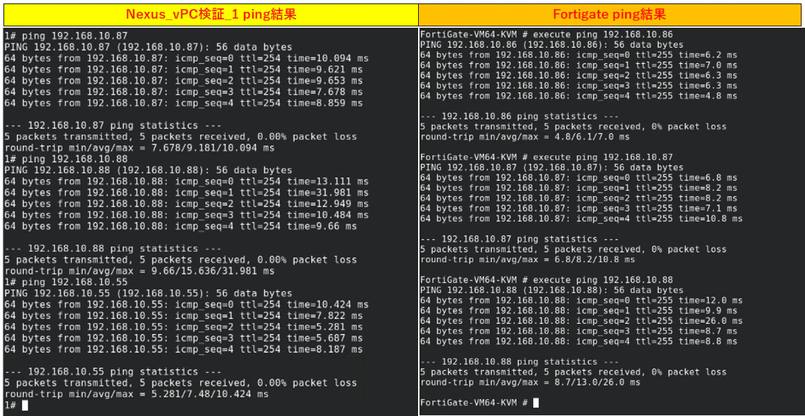
検証②:Nexus vPC検証_2~FWへのリンクを遮断し、単一障害発生時の挙動を確認。
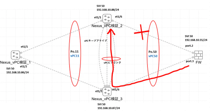
試験の結果、通信は継続され、FWとの疎通は維持された。
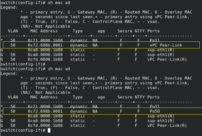
また単一リンク断の状態において、Nexus側のMACアドレステーブルを確認し、vPC peer-link経由でフォワーディングされるためFWのMACアドレス0c72.698b.0001を学習したポートの変化も確認。
まとめ
Cisco機器と他ベンダー機器のFWとを組み合わせたマルチベンダー環境において、LACP はベンダーを跨いでも問題なく成立し、基本的な接続が実現できることを確認した。
既存事例から動作することは分かっていても、実際に構築・検証することで「本当に動く」という理解に変わる。今後も気になった構成は検証し、知見として残していきたい。