データセンター環境で広く利用されているNexusシリーズ。
大規模システムでは1台が落ちてもサービスを止めないことが最重要であり、冗長化の仕組みは設計段階から必須となります。
その代表的な技術がvPC(Virtual Port-Channel) です。
名前だけ聞くと Catalyst 系でのVSS(Virtual Switching System) を思い浮かべる方もいるかもしれませんが、
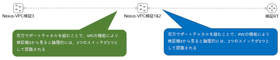
共通する概念は2台のスイッチを論理的に一台として扱えることです。
なぜ vPC が必要とされるのか?
背景には、これまでの冗長化手法である Spanning Tree Protocol (STP) の限界があります。
STP はループ防止のために必ず一部ポートを Blocking 状態にし、結果として帯域・リソースを有効活用できません。
「せっかく配線したのに、半分は遊んでいる」これがDC運用での非効率の典型でした。
vPCはこの無駄を解消する技術です。
2台のスイッチを論理的にまとめ、すべてのポートをアクティブ活用しながらも冗長性を維持できる。
その結果、DCネットワークは 高可用性とリソース効率を両立させることが可能になります。
今回はこちらの技術に関してご説明します。
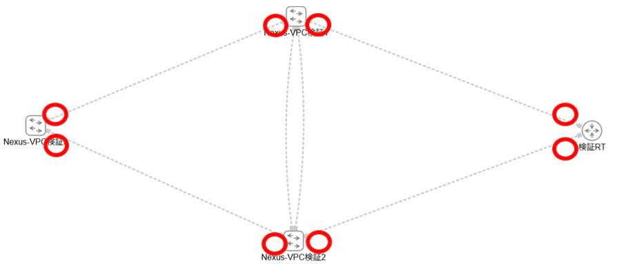
検証構成(物理構成図)
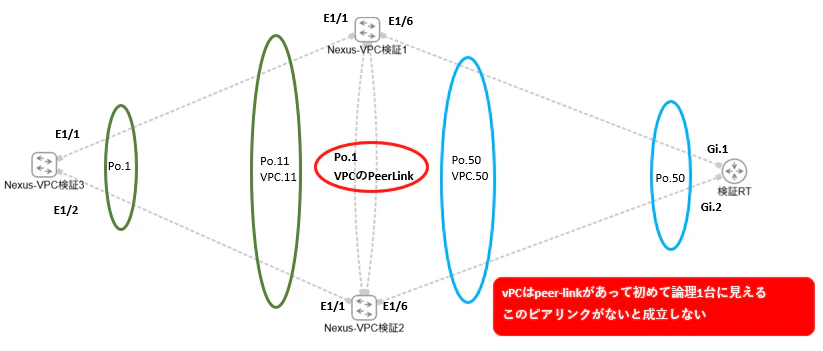
検証構成(論理構成図)
投入コンフィグ
仮想環境での使用機器
・Nexus-vPC検証1-3 Nexus 9000v
・検証RT Catalyst 8000V
Nexus-vPC検証1
feature interface-vlan
feature lacp
feature vpc
feature hsrp

vlan 10
vlan 50

interface mgmt0
 vrf member management
 ip address 10.199.199.101/24

vpc domain 1
 peer-keepalive destination 10.199.199.102 source 10.199.199.101 vrf management
 peer-gateway
 peer-switch
 auto-recovery
 delay restore 150

spanning-tree vlan 10,50 priority 4096

interface port-channel 1
 switchport
 switchport mode trunk
 switchport trunk allowed vlan 10,50
 spanning-tree port type network
 vpc peer-link

interface port-channel 11
 switchport access vlan 10
 spanning-tree port type edge
 vpc 11

interface port-channel 50
 spanning-tree port type edge
 switchport access vlan 50
 vpc 50

interface Ethernet1/1
 switchport access vlan 10
 spanning-tree port type edge
 channel-group 11 mode active

interface Ethernet1/4
 switchport mode trunk
 switchport trunk allowed vlan 10,50
 channel-group 1 mode active

interface Ethernet1/5
 switchport mode trunk
 switchport trunk allowed vlan 10,50
 channel-group 1 mode active

interface Ethernet1/6
 switchport access vlan 50
 spanning-tree port type edge
 channel-group 50 mode active

track 11 interface port-channel 11 line-protocol
track 50 interface port-channel 50 line-protocol

interface Vlan 10
  ip address 192.168.10.101/24
  hsrp 10
  ip 192.168.10.254
  preempt delay minimum 30
  priority 110
  track 11 decrement 50
  no shutdown

interface Vlan 50
 ip address 50.168.10.103/24
 hsrp 50
 ip 50.168.10.254
 priority 110
 preempt delay minimum 30
 track 50 decrement 50
 no shutdown
Nexus-VPC検証2
feature interface-vlan
feature lacp
feature vpc
feature hsrp

vlan 10
vlan 50

interface mgmt0
 vrf member management
 ip address 10.199.199.102/24

vpc domain 1
 peer-keepalive destination 10.199.199.101 source 10.199.199.102 vrf management
 peer-gateway
 peer-switch
 auto-recovery
 delay restore 150

spanning-tree vlan 10,50 priority 4096

interface port-channel 1
 switchport
 switchport mode trunk
 switchport trunk allowed vlan 10,50
 spanning-tree port type network
 vpc peer-link

interface port-channel 11
 switchport access vlan 10
 spanning-tree port type edge
 vpc 11

interface port-channel 50
spanning-tree port type edge
 switchport access  vlan 50
 vpc 50

interface Ethernet1/1
 switchport access vlan 10
 spanning-tree port type edge
 channel-group 11 mode active

interface Ethernet1/4
 switchport mode trunk
 switchport trunk allowed vlan 10,50
 channel-group 1 mode active

interface Ethernet1/5
 switchport mode trunk
 switchport trunk allowed vlan 10,50
 channel-group 1 mode active

interface Ethernet1/6
 switchport access vlan 50
 spanning-tree port type edge
 channel-group 50 mode active

track 11 interface port-channel 11 line-protocol
track 50 interface port-channel 50 line-protocol

interface Vlan 10
 ip address 192.168.10.102/24
 hsrp 10
 ip 192.168.10.254
 preempt delay minimum 30
 track 11 decrement 50
 no shutdown

interface Vlan 50
 ip address 50.168.10.104/24
 hsrp 50
 ip 50.168.10.254
 preempt delay minimum 30
 track 50 decrement 50
 no shutdown
Nexus-VPC検証3
feature interface-vlan
feature lacp
feature vpc
feature hsrp

vlan 50

interface port-channel 50
 switchport access  vlan 50
 interface ethernet1/1
 switchport access  vlan 50
 channel-group 50 mode active

interface Ethernet1/2
 switchport access  vlan 50
 channel-group 50 mode active

interface vlan 50
 ip address 50.168.10.102/24
 no shutdown

ip route 192.168.10.0 255.255.255.0 50.168.10.254
検証RT
interface Port-channel 1
 ip address 192.168.10.1 255.255.255.0

interface GigabitEthernet1
 negotiation auto
 channel-group 1 mode active

interface GigabitEthernet2
 negotiation auto
 channel-group 1 mode active

ip route 0.0.0.0 0.0.0.0 192.168.10.254
コンフィグ作成時の注意ポイント
STPポートタイプの使い分け
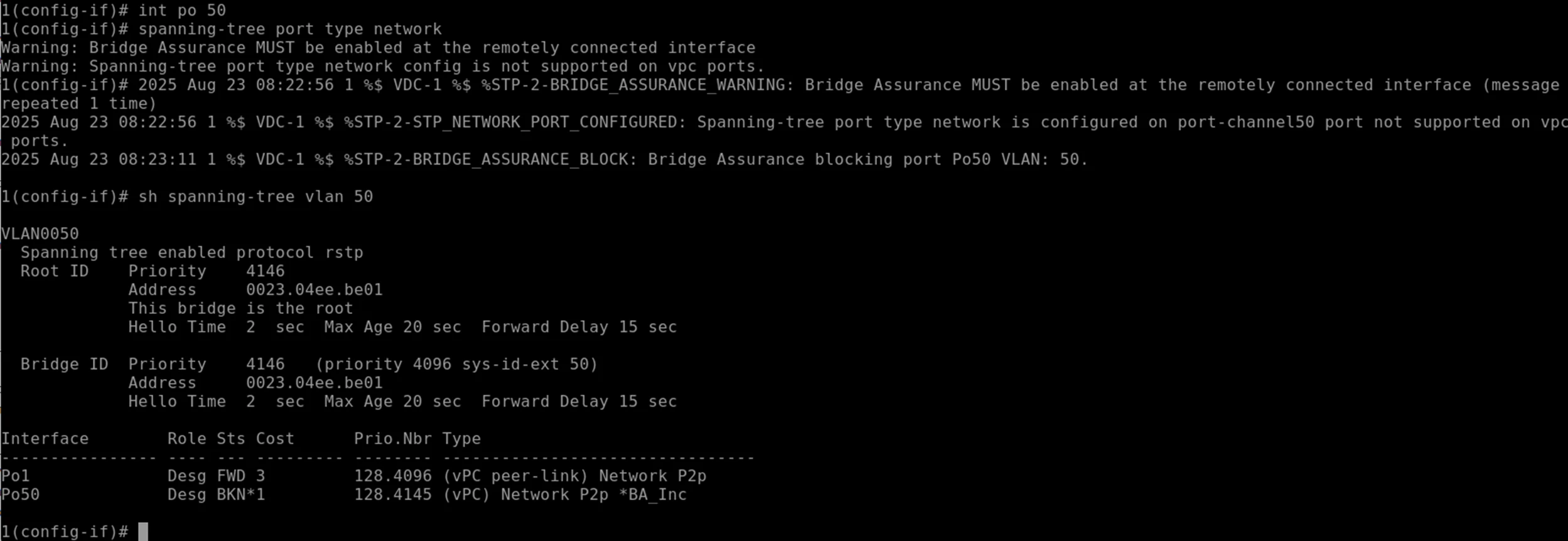
①spanning-tree port type network
このコンフィグですが、これはpeer-link間(検証構成図だとPo.1の個所)だけに設定する
このポート以外のインターフェースに設定した場合、Bridge Assuranceが発生。ポートのブロッキングが起き、ポートチャネルが成立せず即死級のインパクトになります。
実際にやってみた(※絶対に真似しないでください)
対向の検証RTにつながっているポートチャネル50を対象
①コンフィグ投入前
エッジポートとしてP2Pとして機能
②コンフィグ投入後
ブロッキング状態に変化のアラートが上がり、スパニングツリーの状態もブロッキングに変化
③元のエッジポートのコンフィグを投入して切り戻し
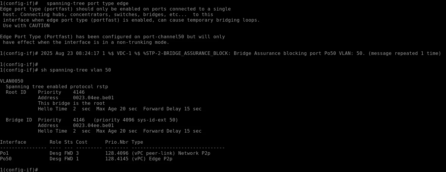
結果、元の状態に戻る。
②spanning-tree port type edge
peer-link間以外、例えば対向先につながっているポート、サーバーにつながっているポートには、このコンフィグを使用する。
投入結果
ポートチャネル結果
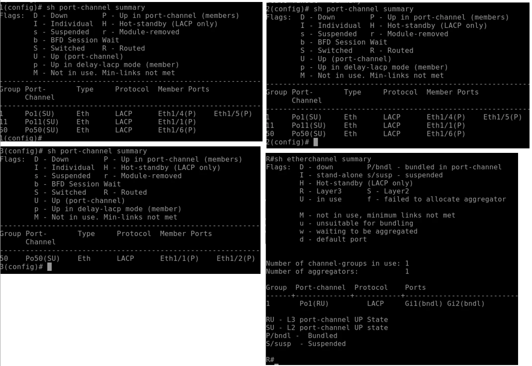
ポートチャネルが全て組めていることを確認
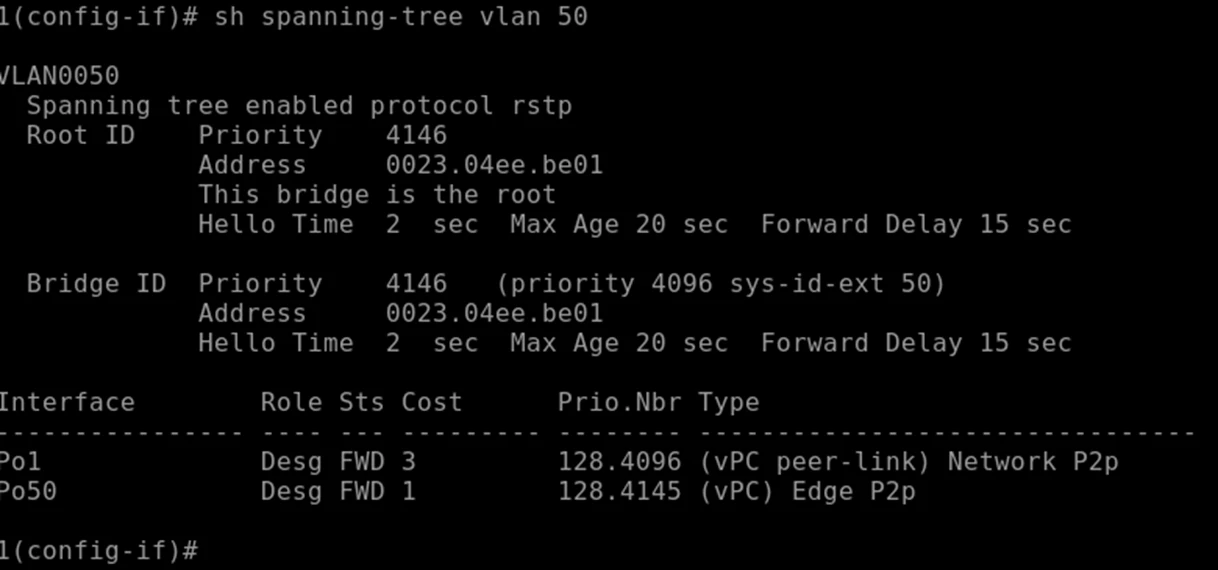
STP結果
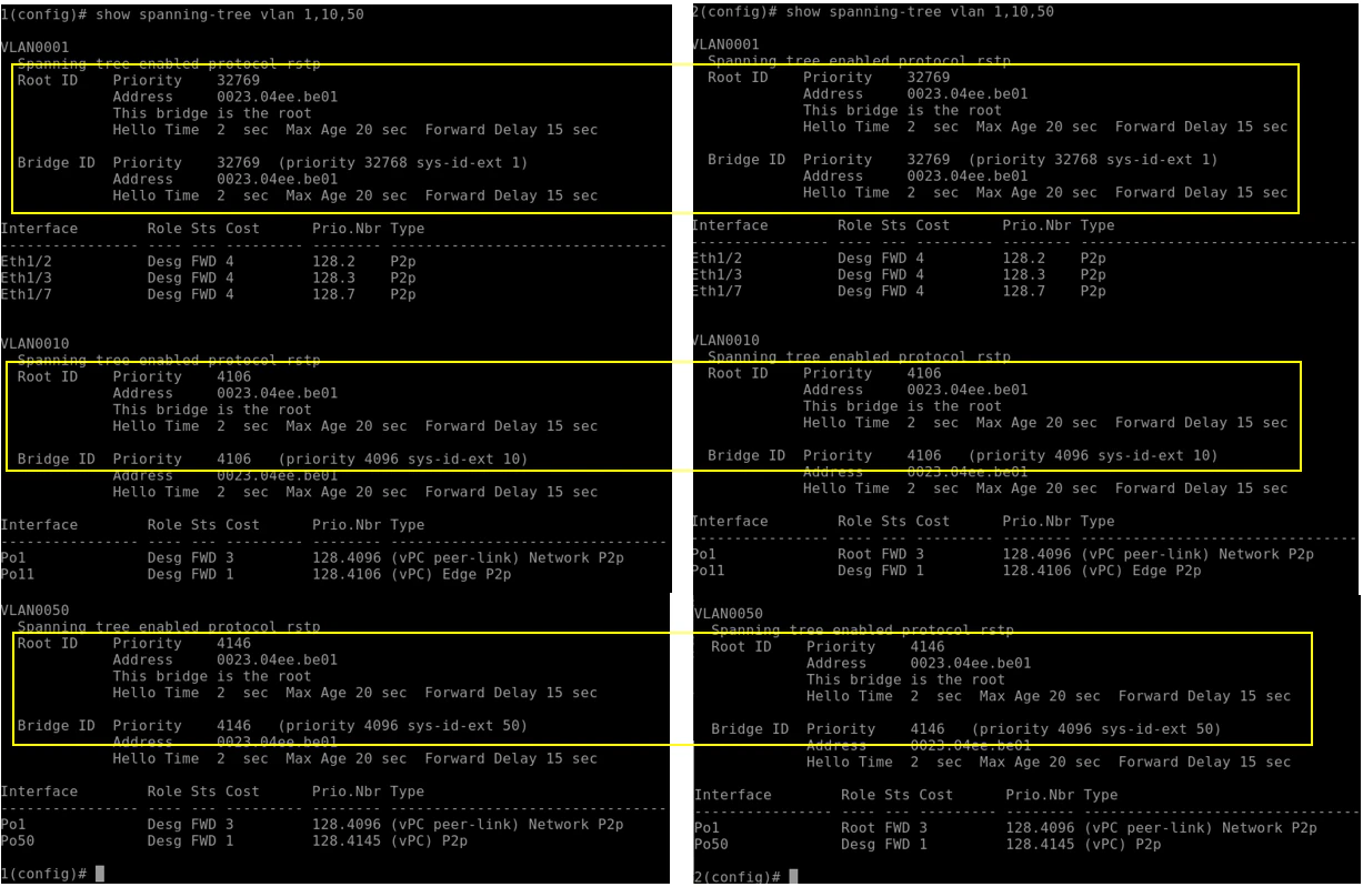
検証機1と2に設定した peer-switch コンフィグ
この結果により、各VLANのスパツリのプライオリティがすべて同じになり
両方ともルートブリッジとなっている
結果、ステータスもフォワードとなりブロッキングポートが存在してない。
vPC結果
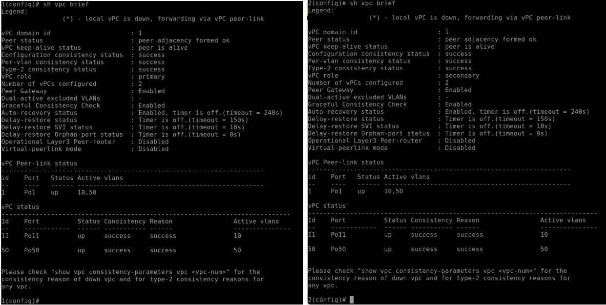
対向機器に対して設定したVPCが成立していることを確認
HSRP結果
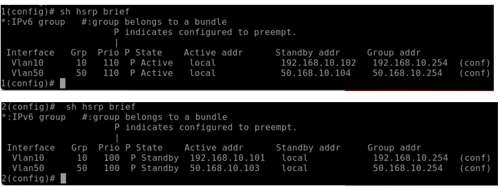
上か検証機1、下が検証機2
それぞれHSRPが機能していることを確認
検証
HSRP切り替え
検証機1
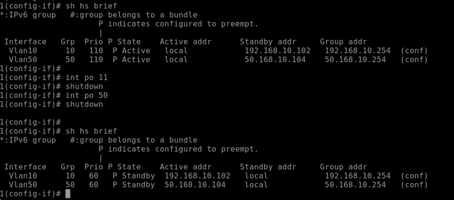
ポートチャネルがダウンした後、優先が切り替わっていることを確認。
検証機2
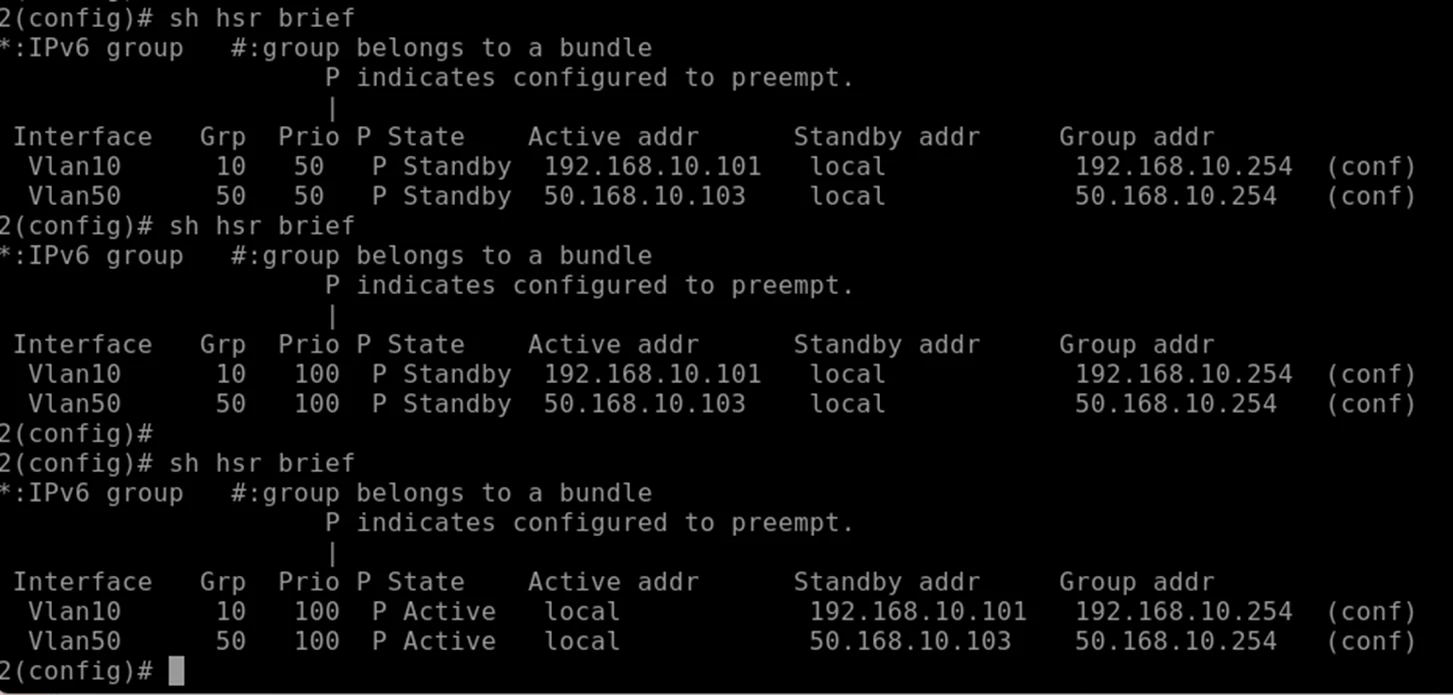
ポートチャネルがダウンした後、優先が切り替わっていることを確認。
ping疎通
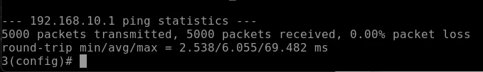
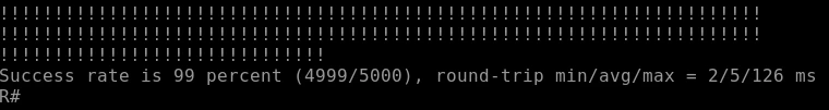
検証RT⇔検証3においてHSRPの切り変わった瞬間、一発のみ落ちた
これ以外は通信の異常なし。
まとめ
いかがでしたでしょうか。
今回は、Cisco Nexus を用いたスイッチ冗長化の代表的手法である vPCについて、最小構成での検証をベースに解説しました。
本記事で紹介したのはシンプルな構成ですが、実務のデータセンターネットワークでは、この構成が複数組み合わさり、複雑かつ大規模なシステムが成り立っています。
また最近では、vPC に加えて EVPN-VXLAN を活用し、ゲートウェイをファブリック全体で冗長化・分散させる構成が主流になりつつあります。こうしたアーキテクチャは、従来の HSRPなどの構成に依存しない、よりスケーラブルな冗長化手法として注目されています。
今後は、こうした次世代データセンターネットワークの冗長化についても記事にしていきたいと思います。