はじめに
KV260 には Pmod インターフェース規格に準拠したコネクタ(12pin) があります。
この Pmod コネクタは KV260 に搭載されている ZynqMP の PL(Programmable Logic)側に接続されています。
KV260 の Pmod コネクタ を Type1A(expanded GPIO) として使う場合、PL側に AXI-GPIO や独自の IP を用意する方法がありますが、この記事では PS(Processing System)側の GPIO コントローラーから EMIO を通して PL側に接続する方法を紹介します。PS側の GPIO を使う利点は次のとおりです。
- PL側に必要なリソースが数本の配線リソースのみ。
- PL側に IP が無いので、そのために新に Device Tree や Kernel Driver を用意する必要がない。
なお、この記事で紹介した各種ソースコードおよび FPGA の binary file は github で公開しています。
PL側のビルド
ブロック図
ここでは PL 側に次のブロック図のようなデザインを作ります。

ビルド環境
- Vivado 2025.1.1
Vivado の GUI を使う場合
プロジェクトを作る
Vivado GUI を使ってプロジェクトを作ります。
Vivado > File > Project New(折り畳み)

New Project > Create a New Vivado Project - Next を選択(折り畳み)
New Project > Project Name - Project Name や location は適当に(折り畳み)

New Project > Project Type - RTL Project を選択(折り畳み)

New Project > Add Sources - 空でかまわない(折り畳み)
New Project > Add Constraints - 後で追加するけどとりあえず今は空でかまわない(折り畳み)
New Project > Default Part - Boards > "Kria KV260 Vision AI Starter Kit SOM" を選択(折り畳み)

New Project > New Project Summary - 最後に Finish を選択(折り畳み)

ブロックデザインを作る
Project を開いて、Create Block Design を選択します。
Design name を適当に(ここではデフォルの値の design_1 に)設定します。
ZynqMP の追加
"+" アイコンをクリックして "Zynq Ultrascale+ MPSoC" を選択(折り畳み)

"Run Block Automation" をクリックして ZynqMP の各種コンフィギュレーションを KV260 用に preset(折り畳み)
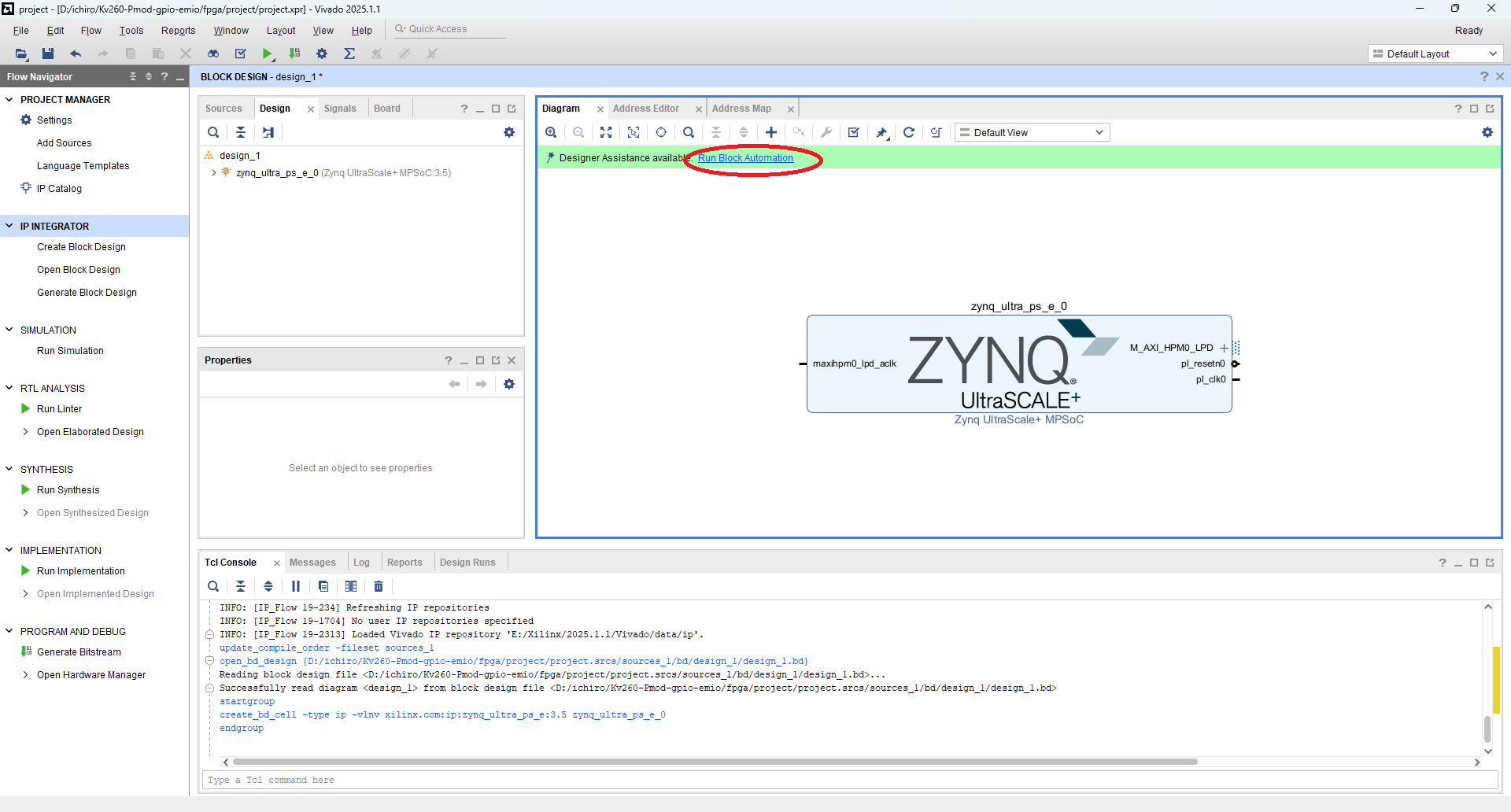

これで ZynqMP が KV260 用に初期化(preset)されました。
ZynqMP のコンフィギュレーション
"Zynq Ultrascale+ MPSoC" の "Block Properties" を選択して Re-customize IP を開く(折り畳み)

ZynqMP を KV260 用に初期化(preset) された状態では、PS-PL 間のインターフェースのうちいくつが有効になっています。そこで必要に応じて使わないインターフェースは無効にします。
ここではとりあえず全てのインターフェースを無効にしています。
Re-customize IP > PS-PL Configureation(折り畳み)
- General > Interrupts > PL to PS の "IRQ0[0-7]" を 0 にします。
- Fabraic Reset Enable のチェックボックスを外して Reset 出力を無効にします。
- PS-PL Interfaces > Master Interfaces の "AXI HCPM0 FPD" と "AXI HPM1 FPD" のチェックボックスを外してこれらのインターフェースを無効にします。

Re-customize IP > Clock Configureation(折り畳み)
- Clock Configuration > Output Clocks > PL Fabric Clocks から PL0 と PL1 のチェックボックスを外してこれらのクロック出力を無効にします。

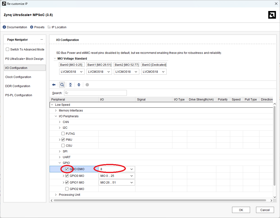
最後に GPIO の EMIO を有効にします。
Re-customize IP > I/O Configuration > GPIO > GPIO EMIO(折り畳み)
具体的には I/O Configuration > Low Speed > I/O Peripherals > GPIO の "GPIO EMIO" のチェックボックスをチェックし、使う GPIO EMIO の本数を設定します。
ここでは Pmod expanded GPIO にあわせて8本を設定しています。
外部ピンの追加と接続
次に GPIO EMIO 外部ピンに繋げます。ここでは比較的簡単にできる "Make External" コマンドを使います。
GPIO_0 > Make External(折り畳み)

"Make External" コマンドでは外部ポート名が適当に付けられてしまいます(ここでは "GPIO_0_0")。
必要に応じてポート名を変更してください。
やり方は External Interface Properties の Name: の値を変更します。
ここでは PMOD_GPIO に変更しています。
この名前は後述のコンストレーションファイルでピンアサインする際に使用します。
External Interface Properties > Name:(折り畳み)

おまけ(FAN 制御)
Pmod 制御だけでは勿体無いと言う事で、FAN 制御用の信号も外部ポートに出力します。
KV260 の FAN 制御に関しては以下の記事を参照してください。
コンストレーションファイルの追加
ピンアサインなどを記述したコンストレーションファイルを追加します。このファイルについては後述します。
具体的には PROJECT MANAGER > Add Sources > Add or Create Constraints から追加するファイルを指定します。
PROJECT MANAGER > Add Sources > Add or Create Constraints(折り畳み)

Wrapper File の生成
インプリメンテーション(論理合成&配置配線)で使用するためのラッパーファイルを生成します。
具体的には、IP INTEGRATOR > Sources > design_1(design_1.bd) > Create HDL Wrapper... を選択します。
IP INTEGRATOR > Sources > design_1(design_1.bd) > Create HDL Wrapper...(折り畳み)

ビットストリームファイルの生成
PROGRAM AND DEBUG > Generate Bitstream を選択して ビットストリームファイルを生成します。
Vivado の CUI(Tcl) を使う場合
プロジェクトを作る
ここでは次のような Tcl スクリプトを使ってプロジェクトを作ります。
create_project.tcl(全文 - ちょっと大きいので折り畳み)
#
# create_project.tcl  Tcl script for creating project
#

set project_directory       [file dirname [info script]]
set project_name            "project"
set board_part              [get_board_parts -quiet -latest_file_version "*kv260*"]
lappend constrs_file_list   [file join $project_directory "design_1_pin.xdc" ]
set design_bd_tcl_file      [file join $project_directory "design_1_bd.tcl"  ]
#
# Create project
#
if {[info exists project_name     ] == 0} {
    set project_name        "project"
}
if {[info exists project_directory] == 0} {
    set project_directory   [pwd]
}
cd $project_directory
create_project -force $project_name $project_directory
#
# Set project properties
#
if       {[info exists board_part ] && [string equal $board_part  "" ] == 0} {
    set_property "board_part"     $board_part      [current_project]
} elseif {[info exists device_part] && [string equal $device_part "" ] == 0} {
    set_property "part"           $device_part     [current_project]
} else {
    puts "ERROR: Please set board_part or device_part."
    return 1
}
set_property "default_lib"        "xil_defaultlib" [current_project]
set_property "simulator_language" "Mixed"          [current_project]
set_property "target_language"    "VHDL"           [current_project]
#
# Create fileset "sources_1"
#
if {[string equal [get_filesets -quiet sources_1] ""]} {
    create_fileset -srcset sources_1
}
#
# Create fileset "constrs_1"
#
if {[string equal [get_filesets -quiet constrs_1] ""]} {
    create_fileset -constrset constrs_1
}
#
# Create fileset "sim_1"
#
if {[string equal [get_filesets -quiet sim_1] ""]} {
    create_fileset -simset sim_1
}
#
# Create run "synth_1" and set property
#
set synth_1_flow     "Vivado Synthesis 2020"
set synth_1_strategy "Vivado Synthesis Defaults"
if {[string equal [get_runs -quiet synth_1] ""]} {
    create_run -name synth_1 -flow $synth_1_flow -strategy $synth_1_strategy -constrset constrs_1
} else {
    set_property flow     $synth_1_flow     [get_runs synth_1]
    set_property strategy $synth_1_strategy [get_runs synth_1]
}
current_run -synthesis [get_runs synth_1]
#
# Create run "impl_1" and set property
#
set impl_1_flow      "Vivado Implementation 2020"
set impl_1_strategy  "Vivado Implementation Defaults"
if {[string equal [get_runs -quiet impl_1] ""]} {
    create_run -name impl_1 -flow $impl_1_flow -strategy $impl_1_strategy -constrset constrs_1 -parent_run synth_1
} else {
    set_property flow     $impl_1_flow      [get_runs impl_1]
    set_property strategy $impl_1_strategy  [get_runs impl_1]
}
current_run -implementation [get_runs impl_1]
#
# Set IP Repository
#
if {[info exists ip_repo_path_list] && [llength $ip_repo_path_list] > 0 } {
    set_property ip_repo_paths $ip_repo_path_list [current_fileset]
    update_ip_catalog
}
#
# Create block design
#
if {[info exists design_bd_tcl_file]} {
    #
    # Read block design file
    #
    source $design_bd_tcl_file
    #
    # Save block design
    #
    regenerate_bd_layout
    save_bd_design
    #
    # Generate wrapper files
    #
    set design_bd_name  [get_bd_designs]
    make_wrapper -files [get_files $design_bd_name.bd] -top -import
}
#
# Import pin files
#
if {[info exists constrs_file_list] && [llength $constrs_file_list] > 0 } {
    add_files    -fileset constrs_1 -norecurse $constrs_file_list
}
この Tcl スクリプトの概要は次の記事を参照してください。
次のように create_project.tcl を実行することで、プロジェクトを作って、ブロックデザインを作ります。
Vivado > Tools > Run Tcl Script... > create_project.tcl
以下では create_project.tcl の一部を説明します。
create_project.tcl(抜粋1) - Boards Property の設定(折り畳み)
以下の所でボードを示すプロパティに KV260 を指定しています。
  (前略)
  :
set board_part              [get_board_parts -quiet -latest_file_version "*kv260*"]
  :
  (中略)
  :
if       {[info exists board_part ] && [string equal $board_part  "" ] == 0} {
    set_property "board_part"     $board_part      [current_project]
} elseif {[info exists device_part] && [string equal $device_part "" ] == 0} {
    set_property "part"           $device_part     [current_project]
} else {
    puts "ERROR: Please set board_part or device_part."
    return 1
}
  :
  (後略)
create_project.tcl(抜粋2) - Block Design File の読み込み(折り畳み)
ブロックデザインファイル(design_1_bd.tcl)を読み込みます。このファイルに関しては後述します。
  (前略)
  :
set design_bd_tcl_file      [file join $project_directory "design_1_bd.tcl"  ]
  :
  (中略)
  :
if {[info exists design_bd_tcl_file]} {
    #
    # Read block design file
    #
    source $design_bd_tcl_file
    #
    # Save block design
    #
    regenerate_bd_layout
    save_bd_design
    #
    # Generate wrapper files
    #
    set design_bd_name  [get_bd_designs]
    make_wrapper -files [get_files $design_bd_name.bd] -top -import
}
  :
  (後略)
create_project.tcl(抜粋3) - コンストレーションファイルの追加(折り畳み)
ピンアサインなどを記述したコンストレーションファイル(design_1_pin.xdc) を追加します。このファイルについては後述します。
  (前略)
  :
lappend constrs_file_list   [file join $project_directory "design_1_pin.xdc" ]
  :
  (中略)
  :
#
# Import pin files
#
if {[info exists constrs_file_list] && [llength $constrs_file_list] > 0 } {
    add_files    -fileset constrs_1 -norecurse $constrs_file_list
}
ブロックデザインを作る
create_project.tcl では Block Design File(design_1_bd.tcl) を読み込んで実行することでブロックデザインを作っています。ここでは design_1_bd.tcl の説明をします。
design_1_bd.tcl(全文 - ちょっと大きいので折り畳み)
################################################################
# This is a generated script based on design: design_1
#
# Though there are limitations about the generated script,
# the main purpose of this utility is to make learning
# IP Integrator Tcl commands easier.
################################################################

namespace eval _tcl {
proc get_script_folder {} {
   set script_path [file normalize [info script]]
   set script_folder [file dirname $script_path]
   return $script_folder
}
}
variable script_folder
set script_folder [_tcl::get_script_folder]

################################################################
# Check if script is running in correct Vivado version.
################################################################
array set available_vivado_version_list {"2025.1"   "ok"}
array set available_vivado_version_list {"2025.1.1" "ok"}
set available_vivado_version [array names available_vivado_version_list]
set current_vivado_version   [version -short]

if { [string first [lindex [array get available_vivado_version_list $current_vivado_version] 1] "ok"] == -1 } {
   puts ""
   puts "ERROR: This script was generated using Vivado <$available_vivado_version> and is being run in <$current_vivado_version> of Vivado. Please run the script in Vivado <$available_vivado_version> then open the design in Vivado <$current_vivado_version>. Upgrade the design by running \"Tools => Report => Report IP Status...\", then run write_bd_tcl to create an updated script."

   return 1
}

################################################################
# START
################################################################

# To test this script, run the following commands from Vivado Tcl console:
# source design_1_script.tcl

# If there is no project opened, this script will create a
# project, but make sure you do not have an existing project
# <./myproj/project_1.xpr> in the current working folder.

set list_projs [get_projects -quiet]
if { $list_projs eq "" } {
   create_project project_1 myproj -part xck26-sfvc784-2LV-c
   set_property BOARD_PART xilinx.com:kv260_som:part0:1.2 [current_project]
}


# CHANGE DESIGN NAME HERE
variable design_name
set design_name design_1

# If you do not already have an existing IP Integrator design open,
# you can create a design using the following command:
#    create_bd_design $design_name

# Creating design if needed
set errMsg ""
set nRet 0

set cur_design [current_bd_design -quiet]
set list_cells [get_bd_cells -quiet]

if { ${design_name} eq "" } {
   # USE CASES:
   #    1) Design_name not set

   set errMsg "Please set the variable <design_name> to a non-empty value."
   set nRet 1

} elseif { ${cur_design} ne "" && ${list_cells} eq "" } {
   # USE CASES:
   #    2): Current design opened AND is empty AND names same.
   #    3): Current design opened AND is empty AND names diff; design_name NOT in project.
   #    4): Current design opened AND is empty AND names diff; design_name exists in project.

   if { $cur_design ne $design_name } {
      common::send_gid_msg -ssname BD::TCL -id 2001 -severity "INFO" "Changing value of <design_name> from <$design_name> to <$cur_design> since current design is empty."
      set design_name [get_property NAME $cur_design]
   }
   common::send_gid_msg -ssname BD::TCL -id 2002 -severity "INFO" "Constructing design in IPI design <$cur_design>..."

} elseif { ${cur_design} ne "" && $list_cells ne "" && $cur_design eq $design_name } {
   # USE CASES:
   #    5) Current design opened AND has components AND same names.

   set errMsg "Design <$design_name> already exists in your project, please set the variable <design_name> to another value."
   set nRet 1
} elseif { [get_files -quiet ${design_name}.bd] ne "" } {
   # USE CASES:
   #    6) Current opened design, has components, but diff names, design_name exists in project.
   #    7) No opened design, design_name exists in project.

   set errMsg "Design <$design_name> already exists in your project, please set the variable <design_name> to another value."
   set nRet 2

} else {
   # USE CASES:
   #    8) No opened design, design_name not in project.
   #    9) Current opened design, has components, but diff names, design_name not in project.

   common::send_gid_msg -ssname BD::TCL -id 2003 -severity "INFO" "Currently there is no design <$design_name> in project, so creating one..."

   create_bd_design $design_name

   common::send_gid_msg -ssname BD::TCL -id 2004 -severity "INFO" "Making design <$design_name> as current_bd_design."
   current_bd_design $design_name

}

common::send_gid_msg -ssname BD::TCL -id 2005 -severity "INFO" "Currently the variable <design_name> is equal to \"$design_name\"."

if { $nRet != 0 } {
   catch {common::send_gid_msg -ssname BD::TCL -id 2006 -severity "ERROR" $errMsg}
   return $nRet
}

set bCheckIPsPassed 1
##################################################################
# CHECK IPs
##################################################################
set bCheckIPs 1
if { $bCheckIPs == 1 } {
   set list_check_ips "\
xilinx.com:ip:xlslice:1.0\
xilinx.com:ip:zynq_ultra_ps_e:3.5\
"

   set list_ips_missing ""
   common::send_gid_msg -ssname BD::TCL -id 2011 -severity "INFO" "Checking if the following IPs exist in the project's IP catalog: $list_check_ips ."

   foreach ip_vlnv $list_check_ips {
      set ip_obj [get_ipdefs -all $ip_vlnv]
      if { $ip_obj eq "" } {
         lappend list_ips_missing $ip_vlnv
      }
   }

   if { $list_ips_missing ne "" } {
      catch {common::send_gid_msg -ssname BD::TCL -id 2012 -severity "ERROR" "The following IPs are not found in the IP Catalog:\n  $list_ips_missing\n\nResolution: Please add the repository containing the IP(s) to the project." }
      set bCheckIPsPassed 0
   }

}

if { $bCheckIPsPassed != 1 } {
  common::send_gid_msg -ssname BD::TCL -id 2023 -severity "WARNING" "Will not continue with creation of design due to the error(s) above."
  return 3
}

##################################################################
# DESIGN PROCs
##################################################################

source [file join $project_directory "add_fan_enable.tcl"  ]
source [file join $project_directory "add_gpio_emio.tcl"  ]

# Procedure to create entire design; Provide argument to make
# procedure reusable. If parentCell is "", will use root.
proc create_root_design { parentCell } {

  variable script_folder
  variable design_name

  if { $parentCell eq "" } {
     set parentCell [get_bd_cells /]
  }

  # Get object for parentCell
  set parentObj [get_bd_cells $parentCell]
  if { $parentObj == "" } {
     catch {common::send_gid_msg -ssname BD::TCL -id 2090 -severity "ERROR" "Unable to find parent cell <$parentCell>!"}
     return
  }

  # Make sure parentObj is hier blk
  set parentType [get_property TYPE $parentObj]
  if { $parentType ne "hier" } {
     catch {common::send_gid_msg -ssname BD::TCL -id 2091 -severity "ERROR" "Parent <$parentObj> has TYPE = <$parentType>. Expected to be <hier>."}
     return
  }

  # Save current instance; Restore later
  set oldCurInst [current_bd_instance .]

  # Set parent object as current
  current_bd_instance $parentObj


  # Create instance: zynq_ultra_ps_e_0, and set properties
  set zynq_ultra_ps_e_0 [ create_bd_cell -type ip -vlnv xilinx.com:ip:zynq_ultra_ps_e:3.5 zynq_ultra_ps_e_0 ]
  apply_bd_automation -rule xilinx.com:bd_rule:zynq_ultra_ps_e -config {apply_board_preset "1"} $zynq_ultra_ps_e_0
  set_property -dict [list CONFIG.PSU__USE__M_AXI_GP0   {0} ] $zynq_ultra_ps_e_0
  set_property -dict [list CONFIG.PSU__USE__M_AXI_GP1   {0} ] $zynq_ultra_ps_e_0
  set_property -dict [list CONFIG.PSU__USE__IRQ0        {0} ] $zynq_ultra_ps_e_0
  set_property -dict [list CONFIG.PSU__USE__FABRIC__RST {0} ] $zynq_ultra_ps_e_0
  set_property -dict [list CONFIG.PSU__FPGA_PL0_ENABLE  {0} ] $zynq_ultra_ps_e_0
  set_property -dict [list CONFIG.PSU__FPGA_PL1_ENABLE  {0} ] $zynq_ultra_ps_e_0

  #
  # Add FAN_EN
  #
  add_fan_enable $zynq_ultra_ps_e_0 FAN_EN ttc0

  #
  # Add GPIO EMIO
  #
  add_gpio_emio  $zynq_ultra_ps_e_0 PMOD_GPIO 8 PMOD_GPIO_0

  # Restore current instance
  current_bd_instance $oldCurInst

  save_bd_design
}
# End of create_root_design()


##################################################################
# MAIN FLOW
##################################################################

create_root_design ""


common::send_gid_msg -ssname BD::TCL -id 2053 -severity "WARNING" "This Tcl script was generated from a block design that has not been validated. It is possible that design <$design_name> may result in errors during validation."
バージョンチェック
以下は Vivado のバージョンをチェックしています。ここでは、Vivado 2025.1 および 2025.1.1 のみ対応としていますが、場合によっては別のバージョンでも動作することがあります。その場合は available_vivado_version_list にバージョンを追加してください。
design_1_bd.tcl(抜粋1) - バージョンチェック(折り畳み)
  (前略)
  :
################################################################
# Check if script is running in correct Vivado version.
################################################################
array set available_vivado_version_list {"2025.1"   "ok"}
array set available_vivado_version_list {"2025.1.1" "ok"}
set available_vivado_version [array names available_vivado_version_list]
set current_vivado_version   [version -short]

if { [string first [lindex [array get available_vivado_version_list $current_vivado_version] 1] "ok"] == -1 } {
   puts ""
   puts "ERROR: This script was generated using Vivado <$available_vivado_version> and is being run in <$current_vivado_version> of Vivado. Please run the script in Vivado <$available_vivado_version> then open the design in Vivado <$current_vivado_version>. Upgrade the design by running \"Tools => Report => Report IP Status...\", then run write_bd_tcl to create an updated script."

   return 1
}
  :
  (後略)
ZynqMP の追加
以下は "Zynq Ultrascale+ MPSoC" をブロックデザインに追加しています。
変数 "zynq_ultra_ps_e" に追加した IP オブジェクトがセットされます。
"Zynq Ultrascale+ MPSoC" 追加後は ZynqMP の各種コンフィギュレーションを KV260 用に初期化(preset) します。
design_1_bd.tcl(抜粋2) - ZynqMP の追加(折り畳み)
  (前略)
  :
  set zynq_ultra_ps_e_0 [ create_bd_cell -type ip -vlnv xilinx.com:ip:zynq_ultra_ps_e:3.5 zynq_ultra_ps_e_0 ]
  apply_bd_automation -rule xilinx.com:bd_rule:zynq_ultra_ps_e -config {apply_board_preset "1"} $zynq_ultra_ps_e_0
  :
  (後略)
ZynqMP のコンフィギュレーション
ZynqMP を KV260 用に初期化(preset) された状態では、PS-PL 間のインターフェースのうちいくつが有効になっています。そこで必要に応じて使わないインターフェースは無効にします。
ここではとりあえず全てのインターフェースを無効にしています。
design_1_bd.tcl(抜粋3) - ZynqMP のコンフィギュレーション(折り畳み)
  (前略)
  :
  set_property -dict [list CONFIG.PSU__USE__M_AXI_GP0   {0} ] $zynq_ultra_ps_e_0
  set_property -dict [list CONFIG.PSU__USE__M_AXI_GP1   {0} ] $zynq_ultra_ps_e_0
  set_property -dict [list CONFIG.PSU__USE__IRQ0        {0} ] $zynq_ultra_ps_e_0
  set_property -dict [list CONFIG.PSU__USE__FABRIC__RST {0} ] $zynq_ultra_ps_e_0
  set_property -dict [list CONFIG.PSU__FPGA_PL0_ENABLE  {0} ] $zynq_ultra_ps_e_0
  set_property -dict [list CONFIG.PSU__FPGA_PL1_ENABLE  {0} ] $zynq_ultra_ps_e_0
  :
  (後略)
ZynqMP の GPIO(EMIO) を有効にして外部ポートに接続するための Tcl スクリプト(add_gpio_emio.tcl)を用意します。
add_gpio_emio.tcl(折り畳み)
proc add_gpio_emio { zynq_ultra_ps_e_0 port_name num net_name} {

    if { $port_name eq "" } {
        set _port_name GPIO_PORT
    } else {
	set _port_name $port_name
    }

    if { $num eq "" } {
	set _num 8
    } else {
        set _num $num
    }

    if { $net_name eq "" } {
	set _net_name zynq_ultra_ps_e_0_GPIO_0
    } else {
	set _net_name $net_name
    }

    set_property -dict [list CONFIG.PSU__GPIO_EMIO__PERIPHERAL__ENABLE  {1} ] $zynq_ultra_ps_e_0
    set_property -dict [list CONFIG.PSU__GPIO_EMIO__PERIPHERAL__IO    $_num ] $zynq_ultra_ps_e_0

    create_bd_intf_port -mode Master -vlnv xilinx.com:interface:gpio_rtl:1.0 $_port_name
    connect_bd_intf_net -intf_net $_net_name [get_bd_intf_ports $_port_name] [get_bd_intf_pins $zynq_ultra_ps_e_0/GPIO_0]
}
上記の add_gpio_emio.tcl を読み込み、add_gpio_emio プロシージャを実行します。
ここでは外部ポート名に PMOD_GPIO、使用する EMIO の本数を8本にしています。
design_1_bd.tcl(抜粋4) - GPIO(EMIO) と外部ポートの追加(折り畳み)
  (前略)
  :
source [file join $project_directory "add_gpio_emio.tcl"  ]
  :
  (中略)
  :
  #
  # Add GPIO EMIO
  #
  add_gpio_emio  $zynq_ultra_ps_e_0 PMOD_GPIO 8 PMOD_GPIO_0
  :
  (後略)
おまけ(FAN 制御)
Pmod 制御だけでは勿体無いと言う事で、FAN 制御用の信号も外部ポートに出力します。
KV260 の FAN 制御に関しては以下の記事を参照してください。
add_fan_enable.tcl(折り畳み)
proc add_fan_enable { zynq_ultra_ps_e_0 port_name prefix} {

    if { $port_name eq "" } {
        set _port_name FAN_EN
    } else {
	set _port_name $port_name
    }

    if { $prefix eq "" } {
	set _prefix ttc0
    } else {
	set _prefix $prefix
    }

    set _cell_name     "${_prefix}_slice"
    set _net_name_din  "${_cell_name}_din"
    set _net_name_dout "${_cell_name}_dout"

    set_property -dict [list CONFIG.PSU__TTC0__WAVEOUT__ENABLE {1} ] $zynq_ultra_ps_e_0
    set_property -dict [list CONFIG.PSU__TTC0__WAVEOUT__IO {EMIO}  ] $zynq_ultra_ps_e_0

    set _slice_cell    [ create_bd_cell -type ip -vlnv xilinx.com:ip:xlslice:1.0 $_cell_name ]

    set_property -dict [ list CONFIG.DIN_FROM {2} CONFIG.DIN_TO {2} CONFIG.DIN_WIDTH {3} ] $_slice_cell

    create_bd_port -dir O -from 0 -to 0 $_port_name
    connect_bd_net -net $_net_name_dout [get_bd_pins $_slice_cell/Dout] [get_bd_ports $_port_name]
    connect_bd_net -net $_net_name_din  [get_bd_pins $_slice_cell/Din ] [get_bd_pins $zynq_ultra_ps_e_0/emio_ttc0_wave_o]
}
上記の add_fan_enable.tcl を読み込み、add_fan_enable プロシージャを実行します。ここでは外部ポート名に FAN_EN を指定しています。
design_1_bd.tcl(抜粋5) - FAN 制御(折り畳み)
  (前略)
  :
source [file join $project_directory "add_fan_enable.tcl"  ]
  :
  (中略)
  :
  #
  # Add FAN_EN
  #
  add_fan_enable $zynq_ultra_ps_e_0 FAN_EN ttc0
  :
  (後略)
ビットストリームファイルの生成
ここでは次のような Tcl スクリプトを使ってビットストリームファイルを生成します。
implementation.tcl(全文 - ちょっと大きいので折り畳み)
#
# implementation.tcl  Tcl script for implementation
#
#
# Open Project
#
set project_directory       [file dirname [info script]]
set project_name            "project"
#
#
#
if {[info exists project_name     ] == 0} {
    set project_name        "project"
}
if {[info exists project_directory] == 0} {
    set project_directory   [pwd]
}
open_project [file join $project_directory $project_name]
#
# Run Synthesis
#
launch_runs synth_1 -job 4
wait_on_run synth_1
#
# Run Implementation
#
launch_runs impl_1  -job 4
wait_on_run impl_1
open_run    impl_1
report_utilization -file [file join $project_directory "project.rpt" ]
report_timing      -file [file join $project_directory "project.rpt" ] -append
#
# Write Bitstream File
#
launch_runs impl_1 -to_step write_bitstream -job 4
wait_on_run impl_1
#
# Close Project
#
close_project
この Tcl スクリプトの概要は次の記事を参照してください。
次のように implementation.tcl を実行することで、指定されたプロジェクトの論理合成、配置配線、ビットストリームファイルの生成までを行います。
Vivado > Tools > Run Tcl Script... > implementation.tcl
ポートのピンアサインなどの設定
KV260 は "Kria KV260 Vision AI Starter Kit Carrier Card" というベースの基板と AMD Kria K26 SOM(System On Module) というモジュールによって構成されています。
KV260 Carrier Card と K26 SOM は SOM240_1 という 240pin のコネクタで接続されています。
また、K26 SOM には ZynqMP が搭載されています。したがって、GPIO(EMIO) からの Pmod コネクタ への接続は、GPIO(EMIO) - PL(Programmable Logic) - ZynqMP Package Pin - SOM240_1 コネクタ - KV260 Net - Pmod となります。
これをピン毎に表にすると次のようになります。
| GPIO(EMIO) | Programmable Logic | ZynqMP Package Pin | SOM240_1 | KV260 Net | Pmod Pin(Name) |
|---|---|---|---|---|---|
| 0 | PMOD_GPIO_tri_io[0] | H12 | A17 | HDA11 | 1 (S1A) |
| 1 | PMOD_GPIO_tri_io[1] | E10 | D20 | HDA12 | 3 (S2A) |
| 2 | PMOD_GPIO_tri_io[2] | D10 | D21 | HDA13 | 5 (S3A) |
| 3 | PMOD_GPIO_tri_io[3] | C11 | D22 | HDA14 | 7 (S4A) |
| 4 | PMOD_GPIO_tri_io[4] | B10 | B20 | HDA15 | 2 (S1B) |
| 5 | PMOD_GPIO_tri_io[5] | E12 | B21 | HDA16_CC | 4 (S2B) |
| 6 | PMOD_GPIO_tri_io[6] | D11 | B22 | HDA17 | 6 (S3B) |
| 7 | PMOD_GPIO_tri_io[7] | B11 | C22 | HDA18 | 8 (S4B) |
なお、GPIO の Interface を Vivado の Block Design で自動的に接続した場合、各 GPIO ポートの名前がポート名+"tri_io[]" になります。
そこで次のようなコンストレーションファイル(design_1_pin.xdc)を用意して、ZynqMP のポートの設定を行います。
具体的には指定したポートに対して、パッケージのピン番号、I/O規格、ドライブ電流を指定します。
design_1_pin.xdc(折り畳み)
#|          property             |            port name             | Kv260 Sch.       | Net Name | SOM240 Connector |
#|-------------------------------|----------------------------------|------------------|----------|------------------|
set_property PACKAGE_PIN A12      [get_ports "FAN_EN"]              ;# FUN             | HDA20    | C24,som240_1_c24 |
set_property IOSTANDARD  LVCMOS33 [get_ports "FAN_EN"]              ;
set_property DRIVE       16       [get_ports "FAN_EN"]              ;

#|          property             |            port name             | Pmod | Kv260 Sch.| Net Name | SOM240 Connector |
#|-------------------------------|----------------------------------|------|-----------|----------|------------------|
set_property PACKAGE_PIN H12      [get_ports "PMOD_GPIO_tri_io[0]"] ;# S1A | J2.1      | HDA11    | A17,som240_1_a17 |
set_property IOSTANDARD  LVCMOS33 [get_ports "PMOD_GPIO_tri_io[0]"] ;
set_property DRIVE       16       [get_ports "PMOD_GPIO_tri_io[0]"] ;
set_property PACKAGE_PIN E10      [get_ports "PMOD_GPIO_tri_io[1]"] ;# S2A | J2.3      | HDA12    | D20,som240_1_d20 |
set_property IOSTANDARD  LVCMOS33 [get_ports "PMOD_GPIO_tri_io[1]"] ;
set_property DRIVE       16       [get_ports "PMOD_GPIO_tri_io[1]"] ;
set_property PACKAGE_PIN D10      [get_ports "PMOD_GPIO_tri_io[2]"] ;# S3A | J2.5      | HDA13    | D21,som240_1_d21 |
set_property IOSTANDARD  LVCMOS33 [get_ports "PMOD_GPIO_tri_io[2]"] ;
set_property DRIVE       16       [get_ports "PMOD_GPIO_tri_io[2]"] ;
set_property PACKAGE_PIN C11      [get_ports "PMOD_GPIO_tri_io[3]"] ;# S4A | J2.7      | HDA14    | D22,som240_1_d22 |
set_property IOSTANDARD  LVCMOS33 [get_ports "PMOD_GPIO_tri_io[3]"] ;
set_property DRIVE       16       [get_ports "PMOD_GPIO_tri_io[3]"] ;
set_property PACKAGE_PIN B10      [get_ports "PMOD_GPIO_tri_io[4]"] ;# S1B | J2.2      | HDA15    | B20,som240_1_b20 |
set_property IOSTANDARD  LVCMOS33 [get_ports "PMOD_GPIO_tri_io[4]"] ;
set_property DRIVE       16       [get_ports "PMOD_GPIO_tri_io[4]"] ;
set_property PACKAGE_PIN E12      [get_ports "PMOD_GPIO_tri_io[5]"] ;# S2B | J2.4      | HDA16_CC | B21,som240_1_b21 |
set_property IOSTANDARD  LVCMOS33 [get_ports "PMOD_GPIO_tri_io[5]"] ;
set_property DRIVE       16       [get_ports "PMOD_GPIO_tri_io[5]"] ;
set_property PACKAGE_PIN D11      [get_ports "PMOD_GPIO_tri_io[6]"] ;# S3B | J2.6      | HDA17    | B22,som240_1_b22 |
set_property IOSTANDARD  LVCMOS33 [get_ports "PMOD_GPIO_tri_io[6]"] ;
set_property DRIVE       16       [get_ports "PMOD_GPIO_tri_io[6]"] ;
set_property PACKAGE_PIN B11      [get_ports "PMOD_GPIO_tri_io[7]"] ;# S4B | J2.8      | HDA18    | C22,som240_1_c22 |
set_property IOSTANDARD  LVCMOS33 [get_ports "PMOD_GPIO_tri_io[7]"] ;
set_property DRIVE       16       [get_ports "PMOD_GPIO_tri_io[7]"] ;
ブートイメージファイルの生成
生成したビットストリームファイルを Linux の FPGA Manager からロードできるようにブートイメージファイルに変換します。
具体的には次のような BIF(Boot Image Format)の定義ファイル(kv260-pmod-gpio-emio.bif) を用意します。
all:
{
	[destination_device = pl] project.runs/impl_1/design_1_wrapper.bit
}
次のように kv260-pmod-gpio-emio.bif を bootgen コマンドに指定することでブートイメージファイルを生成します。
shell$ bootgen -image kv260-pmod-gpio-emio.bif -arch zynqmp -o ../kv260-pmod-gpio-emio.bin
Linux からの制御
実行環境
この記事では実行環境として ZynqMP-FPGA-Debian13 を使います。
PLへブートイメージファイルをプログラム
Device Tree Overlay を使う場合
Device Tree Overlay Source を用意
KV260 の PL側へブートイメージファイル(kv260-pmod-gpio-emio.bin)をプログラムするには、Device Tree Overlay を使います。次のような Device Tree Overlay Source ファイル(kv260-pmod-gpio-emio.dts) を用意します。なお、Linux Kernel のバージョンによっては target-path が "/fpga-full" の場合があります。
/dts-v1/; /plugin/;
/ {
	fragment@0 {
		target-path = "/fpga-region";
		__overlay__ {
			firmware-name = "kv260-pmod-gpio-emio.bin";
		};
        };
};
Device Tree Overlay Blob を用意
kv260-pmod-gpio-emio.dts を dtc コマンドで Device Tree Overlay Blob ファイル(kv260-pmod-gpio-emio.dtb) に変換します。
shell$ dtc -I dts -O dtb -o kv260-pmod-gpio-emio.dtb kv260-pmod-gpio-emio.dts
/lib/firmware/kv260-pmod-gpio-emio.bin を用意
shell$ sudo cp kv260-pmod-gpio-emio.bin /lib/firmware/
または
shell$ sudo sh -c 'gzip -d -c kv260-pmod-gpio-emio.bin.gz > /lib/firmware/kv260-pmod-gpio-emio.bin'
Device Tree Overlay Blob を適用
shell$ sudo mkdir /sys/kernel/config/device-tree/overlays/kv260-pmod-gpio-emio
shell$ sudo cp kv260-pmod-gpio-emio.dtb /sys/kernel/config/device-tree/overlays/kv260-pmod-gpio-emio/dtbo
[ 1403.815783] fpga_manager fpga0: writing kv260-pmod-gpio-emio.bin to Xilinx ZynqMP FPGA Manager
[ 1404.290452] OF: overlay: WARNING: memory leak will occur if overlay removed, property: /fpga-region/firmware-name
dmsg で "fpga_manager fpga0: writing kv260-pmod-gpio-emio.bin to Xilinx ZynqMP FPGA Manager" を確認してください。
その他の方法
Device Tree Overlay 以外にも AMD(Xilinx) が提供する各種ユーティリティコマンドを使う方法や、u-boot の段階で PL にプログラムする方法があります。また、KV260 以外のシステムの場合は FSBL(First Stage Boot Loader) でプログラムする方法もあるので、お使いのシステムに応じて PL 側へプログラムしてください。
デバイスドライバとデバイスツリー
この記事では PS(Processing System)側の GPIO コントローラーから EMIO を通して PL側に接続しているため、GPIO ドライバはすでに Linux Kernel に組込まれていて、かつデバイスツリーから有効になっているはずです。
デバイスドライバ
PS(Processing System)側の GPIO コントローラーのデバイスドライバは /drivers/gpio/gpio-zynq.c です。
また、Kconfig は /drivers/gpio/Kconfig の CONFIG_GPIO_ZYNQ です。
したがって、このドライバを Linux Kernel に組み込むには .config に CONFIG_GPIO_ZYNQ=y が必要です。
Zynq と ZynqMP とで共通なので注意してください。
デバイスツリー
KV260 の GPIO コントローラー関連のデバイスツリーは以下のようになっています。
まずは大元の ZynqMP 用のデバイスツリー(arch/arm64/boot/dts/xilinx/zynqmp.dtsi) があります。
arch/arm64/boot/dts/xilinx/zynqmp.dtsi(折り畳み)
	(前略)
	:
	amba: axi {
	   :
	   (中略)
	   :
		gpio: gpio@ff0a0000 {
			compatible = "xlnx,zynqmp-gpio-1.0";
			status = "disabled";
			#gpio-cells = <0x2>;
			gpio-controller;
			interrupt-parent = <&gic>;
			interrupts = <GIC_SPI 16 IRQ_TYPE_LEVEL_HIGH>;
			interrupt-controller;
			#interrupt-cells = <2>;
			reg = <0x0 0xff0a0000 0x0 0x1000>;
			power-domains = <&zynqmp_firmware PD_GPIO>;
		};
	   :
	   (中略)
	   :
	};
	:
	(後略)
次に KV260 用のデバイスツリー(arch/arm64/boot/dts/xilinx/zynqmp-sm-k26-revA.dts) が 上述の zynqmp.dtsi をインクルードして、必要なところだけを上書きしています。
arch/arm64/boot/dts/xilinx/zynqmp-sm-k26-revA.dts(折り畳み)
  :
(前略)
  :
/dts-v1/;

#include "zynqmp.dtsi"
#include "zynqmp-clk-ccf.dtsi"
#include <dt-bindings/input/input.h>
#include <dt-bindings/gpio/gpio.h>
#include <dt-bindings/phy/phy.h>
#include <dt-bindings/pinctrl/pinctrl-zynqmp.h>
  :
(中略)
  :
&gpio {
	status = "okay";
	gpio-line-names = "QSPI_CLK", "QSPI_DQ1", "QSPI_DQ2", "QSPI_DQ3", "QSPI_DQ0", /* 0 - 4 */
			  "QSPI_CS_B", "SPI_CLK", "LED1", "LED2", "SPI_CS_B", /* 5 - 9 */
			  "SPI_MISO", "SPI_MOSI", "FWUEN", "EMMC_DAT0", "EMMC_DAT1", /* 10 - 14 */
			  "EMMC_DAT2", "EMMC_DAT3", "EMMC_DAT4", "EMMC_DAT5", "EMMC_DAT6", /* 15 - 19 */
			  "EMMC_DAT7", "EMMC_CMD", "EMMC_CLK", "EMMC_RST", "I2C1_SCL", /* 20 - 24 */
			  "I2C1_SDA", "", "", "", "", /* 25 - 29 */
			  "", "", "", "", "", /* 30 - 34 */
			  "", "", "", "", "", /* 35 - 39 */
			  "", "", "", "", "", /* 40 - 44 */
			  "", "", "", "", "", /* 45 - 49 */
			  "", "", "", "", "", /* 50 - 54 */
			  "", "", "", "", "", /* 55 - 59 */
			  "", "", "", "", "", /* 60 - 64 */
			  "", "", "", "", "", /* 65 - 69 */
			  "", "", "", "", "", /* 70 - 74 */
			  "", "", "", /* 75 - 77, MIO end and EMIO start */
			  "", "", /* 78 - 79 */
			  "", "", "", "", "", /* 80 - 84 */
			  "", "", "", "", "", /* 85 - 89 */
			  "", "", "", "", "", /* 90 - 94 */
			  "", "", "", "", "", /* 95 - 99 */
			  "", "", "", "", "", /* 100 - 104 */
			  "", "", "", "", "", /* 105 - 109 */
			  "", "", "", "", "", /* 110 - 114 */
			  "", "", "", "", "", /* 115 - 119 */
			  "", "", "", "", "", /* 120 - 124 */
			  "", "", "", "", "", /* 125 - 129 */
			  "", "", "", "", "", /* 130 - 134 */
			  "", "", "", "", "", /* 135 - 139 */
			  "", "", "", "", "", /* 140 - 144 */
			  "", "", "", "", "", /* 145 - 149 */
			  "", "", "", "", "", /* 150 - 154 */
			  "", "", "", "", "", /* 155 - 159 */
			  "", "", "", "", "", /* 160 - 164 */
			  "", "", "", "", "", /* 165 - 169 */
			  "", "", "", ""; /* 170 - 173 */
};
  :
(後略)
status プロパティに "okay" を上書きして GPIO ドライバを有効にしています。
実はデバイスツリーに GPIO の EMIO ポートが何番から始まるのかも書いてあったりします。これによると、GPIO の EMIO の 0 は GPIO ドライバからは 78 に相当するようです。
したがって、GPIO ドライバからみた番号を line とすると、次のように対応できます。
| line | GPIO(EMIO) | Programmable Logic | ZynqMP Package Pin | SOM240_1 | KV260 Net | Pmod Pin(Name) |
|---|---|---|---|---|---|---|
| 78 | 0 | PMOD_GPIO_tri_io[0] | H12 | A17 | HDA11 | 1 (S1A) |
| 79 | 1 | PMOD_GPIO_tri_io[1] | E10 | D20 | HDA12 | 3 (S2A) |
| 80 | 2 | PMOD_GPIO_tri_io[2] | D10 | D21 | HDA13 | 5 (S3A) |
| 81 | 3 | PMOD_GPIO_tri_io[3] | C11 | D22 | HDA14 | 7 (S4A) |
| 82 | 4 | PMOD_GPIO_tri_io[4] | B10 | B20 | HDA15 | 2 (S1B) |
| 83 | 5 | PMOD_GPIO_tri_io[5] | E12 | B21 | HDA16_CC | 4 (S2B) |
| 84 | 6 | PMOD_GPIO_tri_io[6] | D11 | B22 | HDA17 | 6 (S3B) |
| 85 | 7 | PMOD_GPIO_tri_io[7] | B11 | C22 | HDA18 | 8 (S4B) |
gpiod による使用例
Debian 13では、GPIO 制御は libgpiod(gpiod コマンド)を使う方法が標準です。
(昔の /sys/class/gpio(sysfs GPIO)は 非推奨(deprecated) になっています。)
パッケージのインストール
shell$ sudo apt install gpiod
このパッケージにより以下のコマンドがインストールされます。
- gpioinfo
- gpioset
- gpioget
- gpiomon
GPIO コントローラとピンの確認
GPIO コントローラーのとピンの確認には gpioinfo コマンドを使います。
gpioinfo の出力結果(折り畳み)
shell$ sudo gpioinfo
gpiochip0 - 4 lines:
line 0: unnamed input
line 1: unnamed output active-low consumer=reset
line 2: unnamed input
line 3: unnamed input
gpiochip1 - 174 lines:
line 0: "QSPI_CLK" input
line 1: "QSPI_DQ1" input
line 2: "QSPI_DQ2" input
line 3: "QSPI_DQ3" input
line 4: "QSPI_DQ0" input
line 5: "QSPI_CS_B" input
line 6: "SPI_CLK" input
line 7: "LED1" output consumer="heartbeat"
line 8: "LED2" output consumer="vbus_det"
line 9: "SPI_CS_B" input
line 10: "SPI_MISO" input
line 11: "SPI_MOSI" input
line 12: "FWUEN" input active-low consumer="fwuen"
line 13: "EMMC_DAT0" input
line 14: "EMMC_DAT1" input
line 15: "EMMC_DAT2" input
line 16: "EMMC_DAT3" input
line 17: "EMMC_DAT4" input
line 18: "EMMC_DAT5" input
line 19: "EMMC_DAT6" input
line 20: "EMMC_DAT7" input
line 21: "EMMC_CMD" input
line 22: "EMMC_CLK" input
line 23: "EMMC_RST" input
line 24: "I2C1_SCL" output drive=open-drain consumer="scl"
line 25: "I2C1_SDA" input drive=open-drain consumer="sda"
line 26: unnamed input
line 27: unnamed input
line 28: unnamed input
line 29: unnamed input
line 30: unnamed input
line 31: unnamed input
line 32: unnamed input
line 33: unnamed input
line 34: unnamed input
line 35: unnamed input
line 36: unnamed input
line 37: unnamed input
line 38: unnamed output active-low consumer=PHY reset
line 39: unnamed input
line 40: unnamed input
line 41: unnamed input
line 42: unnamed input
line 43: unnamed input
line 44: unnamed output active-low consumer=reset
line 45: unnamed input
line 46: unnamed input
line 47: unnamed input
line 48: unnamed input
line 49: unnamed input
line 50: unnamed input
line 51: unnamed input
line 52: unnamed input
line 53: unnamed input
line 54: unnamed input
line 55: unnamed input
line 56: unnamed input
line 57: unnamed input
line 58: unnamed input
line 59: unnamed input
line 60: unnamed input
line 61: unnamed input
line 62: unnamed input
line 63: unnamed input
line 64: unnamed input
line 65: unnamed input
line 66: unnamed input
line 67: unnamed input
line 68: unnamed input
line 69: unnamed input
line 70: unnamed input
line 71: unnamed input
line 72: unnamed input
line 73: unnamed input
line 74: unnamed input
line 75: unnamed input
line 76: unnamed input
line 77: unnamed input
line 78: unnamed input
line 79: unnamed input
line 80: unnamed input
line 81: unnamed input
line 82: unnamed input
line 83: unnamed input
line 84: unnamed input
line 85: unnamed input
line 86: unnamed input
line 87: unnamed input
line 88: unnamed input
line 89: unnamed input
line 90: unnamed input
line 91: unnamed input
line 92: unnamed input
line 93: unnamed input
line 94: unnamed input
line 95: unnamed input
line 96: unnamed input
line 97: unnamed input
line 98: unnamed input
line 99: unnamed input
line 100: unnamed input
line 101: unnamed input
line 102: unnamed input
line 103: unnamed input
line 104: unnamed input
line 105: unnamed input
line 106: unnamed input
line 107: unnamed input
line 108: unnamed input
line 109: unnamed input
line 110: unnamed input
line 111: unnamed input
line 112: unnamed input
line 113: unnamed input
line 114: unnamed input
line 115: unnamed input
line 116: unnamed input
line 117: unnamed input
line 118: unnamed input
line 119: unnamed input
line 120: unnamed input
line 121: unnamed input
line 122: unnamed input
line 123: unnamed input
line 124: unnamed input
line 125: unnamed input
line 126: unnamed input
line 127: unnamed input
line 128: unnamed input
line 129: unnamed input
line 130: unnamed input
line 131: unnamed input
line 132: unnamed input
line 133: unnamed input
line 134: unnamed input
line 135: unnamed input
line 136: unnamed input
line 137: unnamed input
line 138: unnamed input
line 139: unnamed input
line 140: unnamed input
line 141: unnamed input
line 142: unnamed input
line 143: unnamed input
line 144: unnamed input
line 145: unnamed input
line 146: unnamed input
line 147: unnamed input
line 148: unnamed input
line 149: unnamed input
line 150: unnamed input
line 151: unnamed input
line 152: unnamed input
line 153: unnamed input
line 154: unnamed input
line 155: unnamed input
line 156: unnamed input
line 157: unnamed input
line 158: unnamed input
line 159: unnamed input
line 160: unnamed input
line 161: unnamed input
line 162: unnamed input
line 163: unnamed input
line 164: unnamed input
line 165: unnamed input
line 166: unnamed input
line 167: unnamed input
line 168: unnamed input
line 169: unnamed input
line 170: unnamed input
line 171: unnamed input
line 172: unnamed input
line 173: unnamed input
これによると、GPIO コントローラーとして gpiochip0 と gpiochip1 があるようです。
gpiochip0 の管理しているライン数は4。おそらくこれは ZynqMP のモードピン用でしょう。
gpiochip1 の管理しているライン数は174。おそらくこれが ZynqMP の PS側の GPIO コントローラーだと思われます。デバイスツリーの gpio-line-names プロパティ設定したライン名前も一致します。
Pmod-LEDx8 で Lチカ
Pmod コネクタに Pmod-LEDx8 を接続して gpioset コマンドを使用して動作を確認してみます。
shell$ sudo gpioset -c gpiochip1 -t2s,0 78=0
LED が2秒ほど点灯すれば成功です。
ただし、Pmod のピン番号がどの LED に相当するのかは Pmod-LED のメーカーによって違うかもしれません。私が試したのは「Sipeed Tang Primer 25K アクセサリーモジュール」についてきた「Pmod-LEDx8」 という奴です。
python3-libgpiod による使用例
パッケージのインストール
shell$ sudo apt install python3-libgpiod
Pmod-LEDx8 で Lチカ
次のような python3 のスクリプトを用意します。
pmod-ledx8-sample.py(折り畳み)
import gpiod
import time

class PmodLEDx8:
    def __init__(self, chip_path, lo, hi):
        self.line_settings = gpiod.LineSettings(
            direction    = gpiod.line.Direction.OUTPUT,
            output_value = gpiod.line.Value.INACTIVE,
            active_low   = True
        )
        self.line_low    = lo
        self.line_high   = hi
        self.line_config = {i: self.line_settings for i in range(lo,hi)}
        self.lines       = gpiod.request_lines(
            chip_path,
            consumer     = "pmod-ledx8",
            config       = self.line_config
        )

    def set_value(self, line, value):
        if value == 0:
            self.lines.set_value(line+self.line_low, gpiod.line.Value.INACTIVE)
        else:
            self.lines.set_value(line+self.line_low, gpiod.line.Value.ACTIVE)


if __name__ == '__main__':
    pmod_led = PmodLEDx8('/dev/gpiochip1', 78, 85)
    pmod_led.set_value(0,1)
    time.sleep(2)
    pmod_led.set_value(0,0)
Pmod コネクタに Pmod-LEDx8 を接続して pmod-ledx8-sample.py を実行して動作を確認してみます。
shell$ sudo python3 pmod-ledx8-sample.py
LED が2秒ほど点灯すれば成功です。