"Timer1" 割り込みでLチカ PCとシリアル送受信
・Timer1割り込みで、割り込み関数宣言の書き方を学習。
・USART1では、PPSでピン割付を指定します。
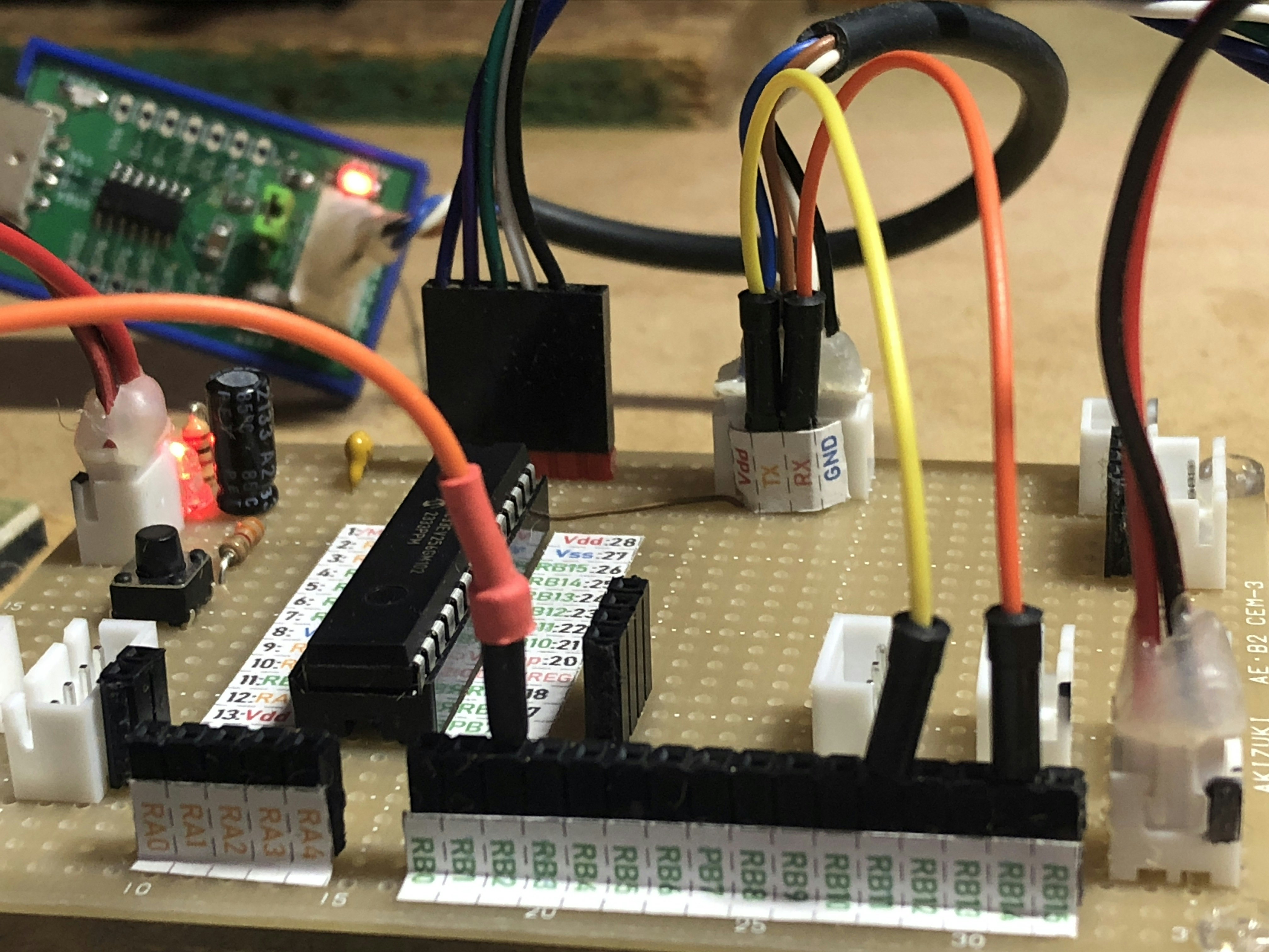
前回、作成した汎用基盤にXHコネクタを増設。ピンソケットは、秋月の分割できるピンソケットを使用。
dsPIC ピン割付 PPS機能
ポートピン割付
RB2: Timer2割り込みで作った、500msインタバルLED点滅
RB11(RP43): USART1 TX
RB14(RPI46): USART2 RX
PPS機能を使って、シリアル通信の送受信ピンを割り付けます。
USRT1 PPS
// Unlock Registers
__builtin_write_OSCCONL(OSCCON & 0xBF);//PPS機能 ロック解除(クリア)
// Assign U1RX To Pin RB14
RPINR18bits.U1RXR= 0x2E;//RPI46
// Configure Output Functions (Table 10-3)
// Assign U1TX To Pin RB11(RP43)
RPOR4bits.RP43R=0b000001;
// Lock Registers
TRISB|=0x4000;//RX受信ピンを入力に設定。
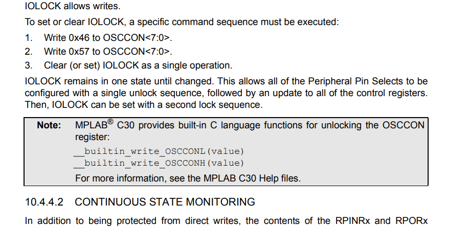
__builtin_write_OSCCONL(OSCCON | 0x40);//PPS機能 ロック再設定(セット)
OSCCONレジスタのIOLOCKビットをクリアすることで、PPSで割付を変更できます。このとき、OSCCONレジスタにもロックがかかっているので、ビルトイン関数を使用したほうが楽です。
Section 10. I/O Ports DS70000598C-page 10-13より
dsPIC 割り込み関数の記述
コンパイラキーワード __attribute__ 属性の付加。
関数のプロトタイプ宣言に、機能追加をコンパイラに指示するときに使用する。変数にも使用できる。
dsPIC XC16 汎用的な割り込み宣言。
割り込み関数であることを、コンパイラに明示する
void __attribute__((interrupt,no_auto_psv)) _T1Interrupt(void);
ROM内のpsvエリアを疑似SRAM const定数として使用、割り込み関数内でアクセスするときの指定は以下のコード
例:const テーブルへのアクセス(auto_psvが必要)
const unsigned int sine_table[256] __attribute__((space(psv))) = { /* データ */ };

void __attribute__((__interrupt__, auto_psv)) _T1Interrupt(void)
{
    unsigned int value = sine_table[100];  // auto_psvがあるから直接アクセス可能
    IFS0bits.T1IF = 0;  // 割り込みフラグクリア
}
割り込み関数の名前
インストールしたコンパイラの docs ディレクトリにある、vector_index.htmlをクリックし、対応機種(33EV256)を検索し、クリックすると、
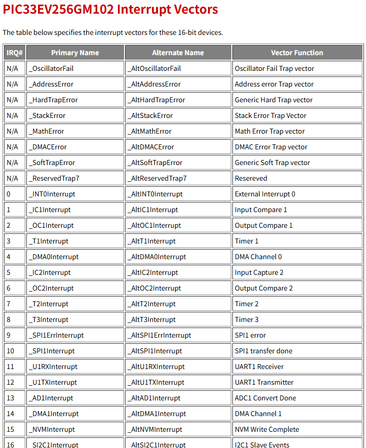
一覧表がでるので、primary nameを使用します。
コード
ds_interrupt.h
#ifndef DS_INTERRUPT_H
#define	DS_INTERRUPT_H

#ifdef	__cplusplus
extern "C" {
#endif

#define FOSC 100000000UL//Mhz Fosc System clock
#define FCY  FOSC/2 //instruction clock frequency libpic30.hより前で宣言すること
#include "xc.h"
#include <p33Exxxx.h>
#include <libpic30.h>
#include <stdint.h>
#include <stdbool.h>

extern void __attribute__((interrupt,no_auto_psv)) _T1Interrupt(void);
extern void __attribute__((interrupt,no_auto_psv)) _U1RXInterrupt(void);


#ifdef	__cplusplus
}
#endif

#endif	/* DS_INTERRUPT_H */
ds_interrupt.c
#include "ds_peripheral.h"
#include "ds_peripheral.h"


/**
 * Timer1割り込み関数 10msインターバル
 */
void __attribute__((interrupt,no_auto_psv)) _T1Interrupt(void)
{
    IFS0bits.T1IF=0;
    Tm1.cnt++;
    if(Tm1.cnt==50)
    {//500msでメインルーチンでLEDを点滅させる。
        Tm1.cnt=0;
        Tm1.fg=true;
        IEC0bits.T1IE=0;
    }
}

/**
 * USART1 受信割り込み関数
 */
void __attribute__((interrupt,no_auto_psv)) _U1RXInterrupt(void)
{
    char ch;
    IFS0bits.U1RXIF=0;
    switch (U1STA&0x000E)//エラー検知
    {
        case 0x0002:
            IEC0bits.U1RXIE=0;
            U1STAbits.OERR=0;
            sprintf(urx.txt,"OERR");
            urx.fg=true;
            return;
            break;
        case 0x0004:
            IEC0bits.U1RXIE=0;
            urx.fg=true;
            sprintf(urx.txt,"FERR");
            return;
            break;
        case 0x0008:
            IEC0bits.U1RXIE=0;
            urx.fg=true;
            sprintf(urx.txt,"PERR");
            return;
            break;
    }

    do{
        ch=U1RXREG;
        if(urx.length>=30)//バッファオーバーフロー
                urx.length=0;
        urx.txt[urx.length]=ch;
        urx.length++;
        if(ch==0x0a && urx.length>=3)//0x0a:'\n'デリミタチェック
        {
            urx.txt[urx.length-2]=0x00;//\n\a終端文字FromPC
            urx.fg=true;  //メインループで処理開始
            IEC0bits.U1RXIE=0;
        }
    }while(U1STAbits.URXDA);//受信バッファが空になるまで読み出しする。

}
ds_peripheral.h
#ifndef DS_PERIPHERAL_H
#define	DS_PERIPHERAL_H

#ifdef	__cplusplus
extern "C" {
#endif

#define FOSC 100000000UL//Mhz Fosc System clock
#define FCY  FOSC/2 //instruction clock frequency libpic30.hより前で宣言すること
#include "xc.h"
#include <p33Exxxx.h>
#include <libpic30.h>
#include <stdint.h>
#include <stdbool.h>

//USART--------------------------------------------------
#define BAUDRATE 115200UL
#define SETBRGVALUE  (unsigned int)((FCY)/(4*BAUDRATE)-1)
//USART受信データ管理-------------------------------------
typedef struct{
    unsigned char length;//受信長
    char txt[30];//受信文字列
    bool fg;//受信完了フラグ
}_urx;

extern volatile _urx urx;
extern void dsUsartInit(void);


//Timer1--------------------------------------------------
typedef struct {
    uint16_t cnt;
    bool fg;
}_timer1;

extern volatile _timer1 Tm1;
extern void dsTimer1_Init(void);

#ifdef	__cplusplus
}
#endif

#endif	/* DS_PERIPHERAL_H */
ds_peripheral.c
#include "ds_peripheral.h"


//USART
volatile _urx urx;
volatile uint8_t txBuf[30];
void dsUsartInit(void)
{
     char ch;
    U1BRG = SETBRGVALUE;
    U1MODEbits.UEN=0b00;
    U1MODEbits.BRGH=1;
    U1MODEbits.PDSEL=0b00;//00:8bits,no parity
    U1MODEbits.STSEL=0;//0:one stop bit
    U1MODEbits.UARTEN=1;
    //受信--------------------------------------
    ch=U1RXREG;//空読み、いらないかも。
    U1STAbits.UTXEN=1;
    U1STAbits.URXISEL=0b00;
    IFS0bits.U1RXIF=0;
    IEC0bits.U1RXIE=1;

    // Unlock Registers
    __builtin_write_OSCCONL(OSCCON & 0xBF);
    // Assign U1RX To Pin RB14
    RPINR18bits.U1RXR= 0x2E;//RPI46
    // Configure Output Functions (Table 10-3)
    // Assign U1TX To Pin RB11(RP43)
    RPOR4bits.RP43R=0b000001;
    // Lock Registers
    TRISB|=0x4000;
    __builtin_write_OSCCONL(OSCCON | 0x40);

    __delay_us(500);
    urx.fg=false;

}

//XC16のprintfではputchの実装はいらない。
/*void putCH(uint8_t _ch)
{
    unsigned int i;

    for(i=0xFFFF; i; i--)
    {
        if(!U1STAbits.UTXBF)
            break;
    }
    U1TXREG=_ch;
}*/

//Timer1
volatile _timer1 Tm1;

void dsTimer1_Init(void)
{
    T1CONbits.TCS=0;//internal clock(Fp)
    T1CONbits.TCKPS=0b01;//1:8
    //interrupt
    IFS0bits.T1IF=0;
    //PR1=0xF2E8;//Fosc=99.495Mhz  10ms 1:8
    PR1=0xF424;//Fosc=100MHz 10ms 1:8
    IEC0bits.T1IE=1;
    //tm1 variable
    Tm1.cnt=0;
    Tm1.fg=false;
    T1CONbits.TON=1;
}
main.c
/*
 * File:   mainXC16.c
 * Created on 2025/06/05
 */

//#define FOSC 99495000//Mhz
#define FOSC 100000000UL//Mhz Fosc System clock
#define FCY  FOSC/2 //instruction clock frequency libpic30.hより前で宣言すること
#include "xc.h"
#include "ds_peripheral.h"

//*************************************************
// DSPIC33EV256GM102 Configuration Bit Settings
//*************************************************

// 'C' source line config statements

#include <p33Exxxx.h>
#include <libpic30.h>

// FSEC
#pragma config BWRP = OFF               // Boot Segment Write-Protect Bit (Boot Segment may be written)
#pragma config BSS = DISABLED           // Boot Segment Code-Protect Level bits (No Protection (other than BWRP))
#pragma config BSS2 = OFF               // Boot Segment Control Bit (No Boot Segment)
#pragma config GWRP = OFF               // General Segment Write-Protect Bit (General Segment may be written)
#pragma config GSS = DISABLED           // General Segment Code-Protect Level bits (No Protection (other than GWRP))
#pragma config CWRP = OFF               // Configuration Segment Write-Protect Bit (Configuration Segment may be written)
#pragma config CSS = DISABLED           // Configuration Segment Code-Protect Level bits (No Protection (other than CWRP))
#pragma config AIVTDIS = DISABLE        // Alternate Interrupt Vector Table Disable Bit  (Disable Alternate Vector Table)

// FBSLIM
#pragma config BSLIM = 0x1FFF           // Boot Segment Code Flash Page Address Limit Bits (Enter Hexadecimal value)

// FOSCSEL
#pragma config FNOSC = FRCDIVN          // Initial oscillator Source Selection Bits (Internal Fast RC (FRC) Oscillator with postscaler)
#pragma config IESO = ON                // Two Speed Oscillator Start-Up Bit (Start up device with FRC,then automatically switch to user selected oscillator source)

// FOSC
#pragma config POSCMD = NONE            // Primary Oscillator Mode Select Bits (Primary Oscillator disabled)
#pragma config OSCIOFNC = OFF           // OSC2 Pin I/O Function Enable Bit (OSC2 is clock output)
#pragma config IOL1WAY = OFF            // Peripheral Pin Select Configuration Bit (Allow Multiple reconfigurations)
#pragma config FCKSM = CSECMD           // Clock Switching Mode Bits (Clock Switching is enabled,Fail-safe Clock Monitor is disabled)
#pragma config PLLKEN = ON              // PLL Lock Enable Bit (Clock switch to PLL source will wait until the PLL lock signal is valid)

// FWDT
#pragma config WDTPOST = PS32768        // Watchdog Timer Postscaler Bits (1:32,768)
#pragma config WDTPRE = PR128           // Watchdog Timer Prescaler Bit (1:128)
#pragma config FWDTEN = OFF             // Watchdog Timer Enable Bits (WDT and SWDTEN Disabled)
#pragma config WINDIS = OFF             // Watchdog Timer Window Enable Bit (Watchdog timer in Non-Window Mode)
#pragma config WDTWIN = WIN25           // Watchdog Window Select Bits (WDT Window is 25% of WDT period)

// FPOR
#pragma config BOREN0 = ON              // Brown Out Reset Detection Bit (BOR is Enabled)

// FICD
#pragma config ICS = PGD3               // ICD Communication Channel Select Bits (Communicate on PGEC3 and PGED3)

// FDMTINTVL
#pragma config DMTIVTL = 0xFFFF         // Lower 16 Bits of 32 Bit DMT Window Interval (Enter Hexadecimal value)

// FDMTINTVH
#pragma config DMTIVTH = 0xFFFF         // Upper 16 Bits of 32 Bit DMT Window Interval (Enter Hexadecimal value)

// FDMTCNTL
#pragma config DMTCNTL = 0xFFFF         // Lower 16 Bits of 32 Bit DMT Instruction Count Time-Out Value (Enter Hexadecimal value)

// FDMTCNTH
#pragma config DMTCNTH = 0xFFFF         // Upper 16 Bits of 32 Bit DMT Instruction Count Time-Out Value (Enter Hexadecimal value)

// FDMT
#pragma config DMTEN = DISABLE          // Dead Man Timer Enable Bit (Dead Man Timer is Disabled and can be enabled by software)

// FDEVOPT
#pragma config PWMLOCK = OFF            // PWM Lock Enable Bit (PWM registers may be written without key sequence)
#pragma config ALTI2C1 = OFF            // Alternate I2C1 Pins Selection Bit (I2C1 mapped to SDA1/SCL1 pins)

// FALTREG
#pragma config CTXT1 = NONE             // Interrupt Priority Level (IPL) Selection Bits For Alternate Working Register Set 1 (Not Assigned)
#pragma config CTXT2 = NONE             // Interrupt Priority Level (IPL) Selection Bits For Alternate Working Register Set 2 (Not Assigned)

// #pragma config statements should precede project file includes.
// Use project enums instead of #define for ON and OFF.


//---------------------------------
//dsPIC初期化関数
// IO,オシレータ設定(100Mhz)
//---------------------------------
 void dsPicInit(void)
 {
    TRISA=0x0000;
    TRISB=0x0000;
    ANSELA=0x0000;
    ANSELB=0x0000;

    __delay_ms(1);
    /**
     * FRC=7.37kHz
     * FOSC=100Mhz
     * OSCTUNEでつじつま合わせ。
     */
    CLKDIVbits.FRCDIV=0b000;//(7.37MHz)
    CLKDIVbits.PLLPRE=0b00000;//N1=2
    CLKDIVbits.PLLPOST=0b00;//N2=2
    PLLFBD = 0x034;//M=52
    OSCTUN  = 0x0003; //100MHz

   __builtin_write_OSCCONH(0x01);
   __builtin_write_OSCCONL(OSCCONL | 0x01);//OSCCONbits.OSWEN=1;
    while(OSCCONbits.COSC!=0b001);
    while(OSCCONbits.LOCK!=1);
 }

 int count;

int main(void)
{
    dsPicInit();
    dsUsartInit();
    dsTimer1_Init();

    while(1)
    {
        if(Tm1.fg)//Timer1割り込み処理
        {
            Tm1.fg=false;
            LATBbits.LATB2=~LATBbits.LATB2;
            IEC0bits.T1IE=1;
        }

        if(urx.fg)//USART1受信割り込み処理
        {
            urx.fg=false;
            printf("%s\n",urx.txt);
            urx.length = 0;
            IEC0bits.U1RXIE=1;
        }
    }
    return 0;
}