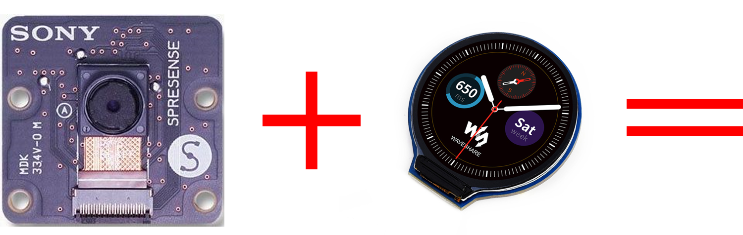
昨日投稿したSpresenseで丸型液晶モジュール 240×240を動かしてみる に続いて、例の丸形液晶ディスプレイモジュールにSpresenseカメラボードで撮影された画像を表示してみます。
必要な材料
今回使用した材料は以下の5つになります。昨日の投稿に加えてSpresense カメラボードが加わっただけです。
1. Spresense Mainボード
お馴染みソニーが展開するSpresenseのMainボード。
本ボードにカメラ用のI/Fコネクタが搭載されており、別途Spresenseカメラボードを追加するとカメラ機能が使えるようになります。

購入サイトはこちら スイッチサイエンス-SPRESENSEメインボード[CXD5602PWBMAIN1]
2. Spresense 拡張ボード
今回もやはりこちらを使います。(将来的にはこのボードがなくても丸形液晶ディスプレイモジュールを動かせるようになりたい。)
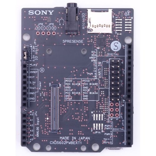
購入サイトはこちら スイッチサイエンス-SPRESENSE拡張ボード[CXD5602PWBEXT1]
3. Spresense カメラボード
今回新たに加わったボード。ソニー製のイメージセンサが搭載されたSpresense用のカメラボード。

購入サイトはこちら スイッチサイエンス-SPRESENSEカメラボード [CXD5602PWBCAM1]
4. 丸形液晶ディスプレイモジュール
この丸い液晶画面にカメラのプレビュー画像を表示させます。

購入サイトはこちら スイッチサイエンス-1.28インチ 丸形液晶ディスプレイモジュール 240×240
5. ジャンパ配線
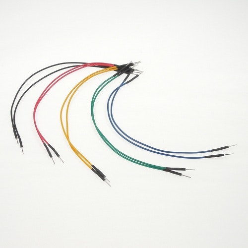
購入サイトはこちら スイッチサイエンス-普通のジャンパワイヤ(オス~オス)
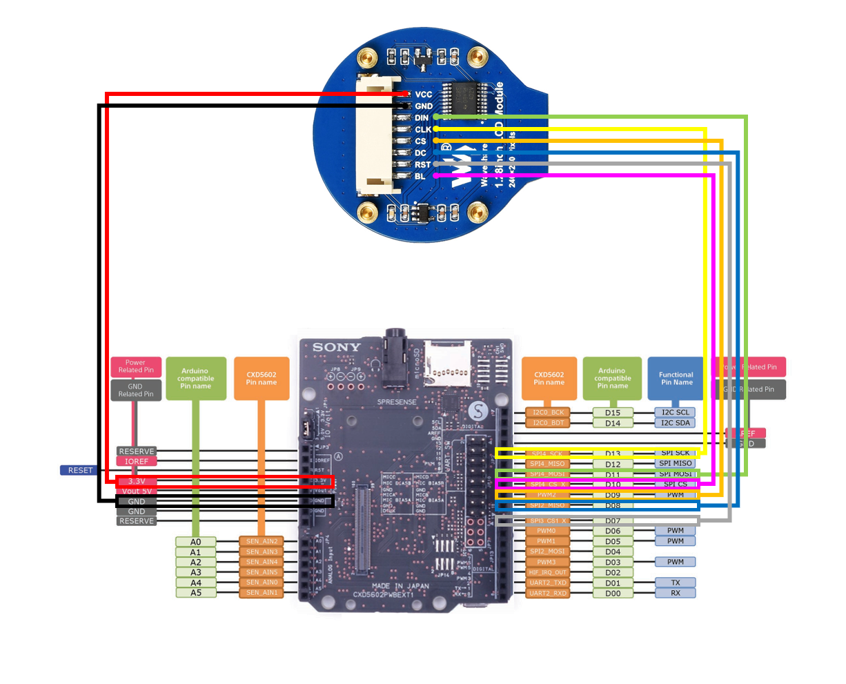
丸形液晶ディスプレイモジュールの接続
Spresense 拡張ボードのIO電圧設定を 5.0V に変えて、以下のように配線するだけでOKです。
今回使うライブラリの機能について
Spresenseカメラボードのプログラムについて
Spresenseの開発環境にはカメラ用のライブラリが含まれており、今回はそれを使います。
カメラの初期化を行い、プレビュー用のCallback関数を指定してあげれば、Callback関数に撮影された画像(CamImage)が渡されるのでそれを液晶に表示させます。
初期化
以下のようにプログラムを記述することで、CamCB(Callback関数)にプレビュー画像が返るようになる。
  /* カメラライブラリ初期化 */
  CamErr err = theCamera.begin();

  /* カメラのプレビュー開始(CamCBはCallback関数) */
  err = theCamera.startStreaming(true, CamCB);

  /* ホワイトバランス設定 */
  err = theCamera.setAutoWhiteBalanceMode(CAM_WHITE_BALANCE_DAYLIGHT);
Callback関数(CamCB)
void CamCB(CamImage img)
{
  /* プレビュー画像が利用可能か否かを確認する */

  if (img.isAvailable())
    {
      /* ここに取得したカメラ画像の加工とディスプレイドライバへ画像を受け渡しするコードを記述する */
    }
  else
    {
      Serial.print("Failed to get video stream image\n");
    }
}
カメラ画像の加工
カメラ画像の加工には clipAndResizeImageByHW と convertPixFormat を使います。
clipAndResizeImageByHWはカメラ画像をクリップ(切り出し)して、サイズを変更することができる関数です。プログラムでも実装可能ですが、この関数を使うとHWで切り出しとリサイズができるようです。
  /**
   * @brief Clip and resize Image with HW 2D accelerator.
   * @details [en] Clip and resize the image with 2D accelerator HW in CXD5602.
   *               First, clip the area specified by the arguments (#lefttop_x, #lefttop_y) - (#rightbottom_x, # rightbottom_y) for the original
   *               image and specify the clipped image with arguments (#width, # height) resize to the size you made.
   *               The resized image is stored in the CamImage instance specified as the first argument with new image buffer created internally.
   *               If any error occured such as zero size case, this returns error code.
   *               This HW accelerator has limitation for resizing as below: <BR>
   *               - Minimum width and height is 12 pixels.
   *               - Maximum width is 768 pixels.
   *               - Maximum height is 1024 pixels.
   *               - Resizing magnification is 2^n or 1/2^n, and resized image size must be integer. <BR>
   *          [ja] CXD5602が持つ2Dアクセラレータを用いた画像のクリッピング及びリサイズを行う。
   *               まず、元画像に対して、引数 (#lefttop_x, #lefttop_y) - (#rightbottom_x, #rightbottom_y) で指定された領域をクリップし、
   *               クリップされた画像に対して引数 (#width, #height)で指定されたサイズにリサイズを行う。
   *               リサイズ後の画像は、内部で新たにImage用のバッファを生成したうえで第1引数に指定されたCamImageインスタンスに結果を格納する。
   *               指定されたサイズがゼロの場合など、何らかのエラーが起きた場合、空のCamImageインスタンスを格納し、エラーコードを返す。
   *               なお、このHWアクセラレータには、リサイズ動作に関して以下の仕様制限があります。<BR>
   *                 イメージの幅、高さの最小ピクセル数は12ピクセル。<BR>
   *                 イメージの幅の最大ピクセル数は768ピクセル。<BR>
   *                 イメージの高さの最大ピクセル数は1024ピクセル。<BR>
   *                 リサイズする場合の倍率は2^n倍もしくは1/2^nとなり、リサイズ後のサイズは整数になる必要がある。 <BR>
   * @return [en] Error codes in #CamErr <BR>
   *         [jp] #CamErr で定義されているエラーコード
   */
  CamErr clipAndResizeImageByHW(
    CamImage &img,     /**< [en] Instance of CamImage with result of resizing. <BR> [ja] リサイズ後の新しいCamImageが格納されるインスタンス */
    int lefttop_x,     /**< [en] Left top X coodinate in original image for clipping. <BR> [ja] 元画像に対して、クリップする左上のX座標 */
    int lefttop_y,     /**< [en] Left top Y coodinate in original image for clipping. <BR> [ja] 元画像に対して、クリップする左上のY座標 */
    int rightbottom_x, /**< [en] Right bottom X coodinate in original image for clipping. <BR> [ja] 元画像に対して、クリップする左上のX座標 */
    int rightbottom_y, /**< [en] Right bottom Y coodinate in original image for clipping. <BR> [ja] 元画像に対して、クリップする左上のY座標 */
    int width,         /**< [en] Width to resize from clipping image  <BR> [ja] クリップされた画像に対して、リサイズする画像の横サイズ */
    int height         /**< [en] Height to resize from clipping image <BR> [ja] クリップされた画像に対して、リサイズする画像の縦サイズ */
  );
convertPixFormatは加工したカメラ画像(YUV形式)を別の形式に変換することができます。
  /**
   * @brief Convert Pixcelformat of the image.
   * @details [en] Convert own image's pixel format. Override Image data. So
   *               original image is discarded. If paramter is the same format
   *               as current, no error and no operation. <BR>
   *          [ja] ピクセルフォーマット変換を行う。画像データは上書きされ、元の
   *               ピクセルフォーマットの画像は破棄される。現在のフォーマットと
   *               同一のフォーマットが設定された場合、何も処理は行われず正常終了する。
   * @return [en] Error codes in #CamErr <BR>
   *         [jp] #CamErr で定義されているエラーコード
   */
  CamErr convertPixFormat(CAM_IMAGE_PIX_FMT to_fmt /**< [en] Pixcel format which is convert to. <BR> [ja] 変換するピクセルフォーマット */);
丸形液晶ディスプレイモジュールのプログラムについて
前回同様、GC9A01 ようにSPIバスの設定と、ディスプレイドライバの設定を使います。
/* More data bus class: https://github.com/moononournation/Arduino_GFX/wiki/Data-Bus-Class */
Arduino_DataBus *bus = new Arduino_HWSPI(8 /* DC */, 9 /* CS */);

/* More display class: https://github.com/moononournation/Arduino_GFX/wiki/Display-Class */
Arduino_GFX *gfx = new Arduino_GC9A01(bus, 7 /* RST */, 0 /* rotation */, true /* IPS */);
また、今回使用するディスプレイドライバ Arduino_GFX には16bitのRGB画像を描画する関数 draw16bitRGBBitmap が用意されているので、これを使って描画を行う。
void draw16bitRGBBitmap(int16_t x, int16_t y, const uint16_t bitmap[], int16_t w, int16_t h);
Cameraプレビュープログラム
以上までの機能を使いプログラムを作成しました。
# include <Arduino_GFX_Library.h>
# include <Camera.h>

/* More data bus class: https://github.com/moononournation/Arduino_GFX/wiki/Data-Bus-Class */
Arduino_DataBus *bus = new Arduino_HWSPI(8 /* DC */, 9 /* CS */);

/* More display class: https://github.com/moononournation/Arduino_GFX/wiki/Display-Class */
Arduino_GFX *gfx = new Arduino_GC9A01(bus, 7 /* RST */, 0 /* rotation */, true /* IPS */);

# define BACKGROUND BLACK
# define BAUDRATE                (115200)

static int16_t w, h;

/**
 * カメラのエラー詳細表示
 */

void printError(enum CamErr err)
{
  Serial.print("Error: ");
  switch (err)
    {
      case CAM_ERR_NO_DEVICE:
        Serial.println("No Device");
        break;
      case CAM_ERR_ILLEGAL_DEVERR:
        Serial.println("Illegal device error");
        break;
      case CAM_ERR_ALREADY_INITIALIZED:
        Serial.println("Already initialized");
        break;
      case CAM_ERR_NOT_INITIALIZED:
        Serial.println("Not initialized");
        break;
      case CAM_ERR_NOT_STILL_INITIALIZED:
        Serial.println("Still picture not initialized");
        break;
      case CAM_ERR_CANT_CREATE_THREAD:
        Serial.println("Failed to create thread");
        break;
      case CAM_ERR_INVALID_PARAM:
        Serial.println("Invalid parameter");
        break;
      case CAM_ERR_NO_MEMORY:
        Serial.println("No memory");
        break;
      case CAM_ERR_USR_INUSED:
        Serial.println("Buffer already in use");
        break;
      case CAM_ERR_NOT_PERMITTED:
        Serial.println("Operation not permitted");
        break;
      default:
        break;
    }
}

/**
 * カメラ画像用CallBack関数
 */

void CamCB(CamImage img)
{
  CamImage small;
  CamErr err;

  /* Check the img instance is available or not. */

  if (img.isAvailable())
    {
      /* 320×240の画像に対し(40, 0)から(279, 239)までの画像を切り出し240×240の画像に変換します */
      /* imgが元画像、smallが切り出し後の画像 */
      err = img.clipAndResizeImageByHW(small, 40, 0, 279, 239, 240, 240);
      if (err != CAM_ERR_SUCCESS)
        {
          printError(err);
        }

      /* YUV画像を16bit Bitmap画像に変換 */
      small.convertPixFormat(CAM_IMAGE_PIX_FMT_RGB565);

      /* ディスプレイドライバに変換後画像をセット */
      gfx->draw16bitRGBBitmap(0, 0, (uint16_t *)small.getImgBuff(), 240, 240);
    }
  else
    {
      Serial.print("Failed to get video stream image\n");
    }
}

void setup(void)
{
  CamErr err;

  /* Open serial communications and wait for port to open */

  Serial.begin(BAUDRATE);
  while (!Serial)
    {
      ; /* wait for serial port to connect. Needed for native USB port only */
    }

  /* begin() without parameters means that
   * number of buffers = 1, 30FPS, QVGA, YUV 4:2:2 format */

  Serial.println("Prepare camera");
  err = theCamera.begin();
  if (err != CAM_ERR_SUCCESS)
    {
      printError(err);
    }

  /* Start video stream.
   * If received video stream data from camera device,
   *  camera library call CamCB.
   */

  Serial.println("Start streaming");
  err = theCamera.startStreaming(true, CamCB);
  if (err != CAM_ERR_SUCCESS)
    {
      printError(err);
    }

  /* Auto white balance configuration */

  Serial.println("Set Auto white balance parameter");
  err = theCamera.setAutoWhiteBalanceMode(CAM_WHITE_BALANCE_DAYLIGHT);
  if (err != CAM_ERR_SUCCESS)
    {
      printError(err);
    }

  /* ディスプレイドライバ初期化 */
  gfx->begin();
  gfx->fillScreen(BACKGROUND);

# ifdef TFT_BL
  pinMode(TFT_BL, OUTPUT);
  digitalWrite(TFT_BL, HIGH);
# endif

  // init LCD constant
  w = gfx->width();
  h = gfx->height();
}

void loop()
{
  /* 今回は`loop`で特に処理を行わないので `sleep(1)` でループさせます。 */
  sleep(1);
}
上記のようにサンプルコードを変更してSpresenseに書き込むと以下のように丸形液晶ディスプレイモジュールにカメラで撮影した画像が表示されました。簡単!!

最後に
SpresenseカメラライブラリとGFX Library for Arduino ライブラリが便利な関数を用意していたので、思った以上に簡単に実現できました。
いつになるかはわかりませんが、今度はSpresenseメインボードとSpresenseカメラボード、そして丸形液晶ディスプレイモジュールだけを使ってより小さくした形で実現させてみたいと思います。