これはなに
書籍12ステップで作る組込みOS自作入門の内容を、Rustで実装していこうと思ってます。
長期戦になる想定なので、1回目の今回は環境構築からマイコンの書き込みまでの内容になります。
手順
- 必要なツールをインストールする
- マイコンを用意する
- テンプレートプロジェクトを使用し、マイコンに書き込む
使用デバイスなど
- PC
- Windows
- WSLを使用し開発
- エディタ
- NeoVim
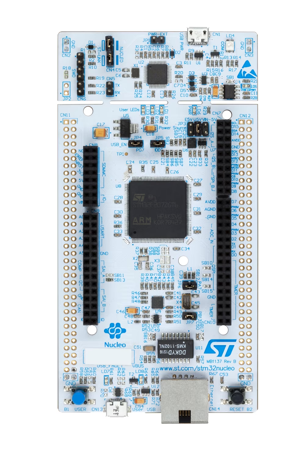
- マイコンボード
- NUCLEO-F439ZI
必要なツール
GDB
GDB: GDB: The GNU Project Debugger
デバッガです。
インストール
Linuxの場合は、aptでインストールできますが、最新版ではないので、今回はソースをダウンロードし、インストールします。
ソースをダウンロード
URLのversionに、任意のバージョンを入れてください。
https://ftp.gnu.org/gnu/gdb/
curl -OL https://ftp.gnu.org/gnu/gdb/gdb-<version>.tar.gz
ファイルを解凍し、インストール
$ tar -xvzf gdb-<version>.tar.gz

$ cd gdb-15.1
gdb-15.1 $ ./configure
gdb-15.1 $ make

// Install
gdb-15.1 $ make install
インストールの確認
$ gdb --version

GNU gdb (GDB) 15.1
Copyright (C) 2024 Free Software Foundation, Inc.
License GPLv3+: GNU GPL version 3 or later <http://gnu.org/licenses/gpl.html>
This is free software: you are free to change and redistribute it.
There is NO WARRANTY, to the extent permitted by law.
OpenOCD
OpenOCDはaptでインストールします。
$ sudo apt install openocd

Open On-Chip Debugger 0.12.0+dev-00683-gac63cd00d (2024-08-16-15:55)
Licensed under GNU GPL v2
For bug reports, read
        http://openocd.org/doc/doxygen/bugs.html
gcc-arm-none-eabi
以下サイトから任意のバージョンをダウンロードします。
curl -OL https://developer.arm.com/-/media/Files/downloads/gnu-rm/10.3-2021.10/gcc-arm-none-eabi-10.3-2021.10-x86_64-linux.tar.bz2
ダウンロードが完了後、ファイルを解凍し、実行できるようにする。
$ sudo tar -xvjf gcc-arm-none-eabi-10.3-2021.10-x86_64-linux.tar.bz2 -C /usr/share/

// シンボリックリンクを追加
$ sudo ln -s /usr/share/gcc-arm-none-eabi-10.3-2021.10/bin/* /usr/bin/
$ sudo apt-get install libncurses5

// 実行確認
$ arm-none-eabi-gcc --version

arm-none-eabi-gcc (GNU Arm Embedded Toolchain 10.3-2021.10) 10.3.1 20210824 (release)
Copyright (C) 2020 Free Software Foundation, Inc.
This is free software; see the source for copying conditions.  There is NO
warranty; not even for MERCHANTABILITY or FITNESS FOR A PARTICULAR PURPOSE.
WSLからボードにアクセスするためのUSBの設定
以下の記事を参考にさせてもらいました。
マイコンのスペックの確認
開発ボードにのっているマイコンの詳細
マイコンのデータシートで確認する場所
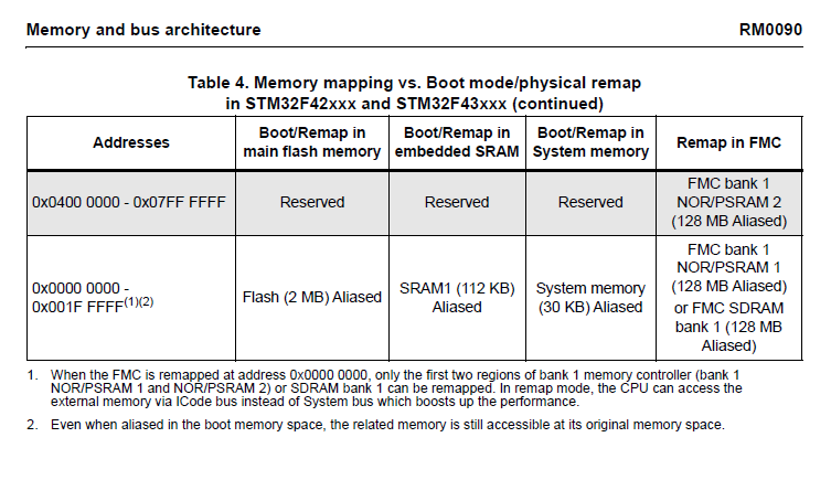
内臓RAM、Flash Memoryのアドレス開始位置とサイズを確認します。
そのほか、必要に応じて、使いたい機能のレジスタなどを確認する。
アプリケーション
Lチカのテンプレートファイルを使用させてもらいます。
このテンプレートファイルでは、32F429IDISCOVERYを使用しているため、ボードにあるLEDのピン番号などが異なるため、一部変更が必要です。
https://www.st.com/en/evaluation-tools/32f429idiscovery.html
ボードのピン配置に合わせて、src/main.rsを編集します。
#![no_std]
#![no_main]

use panic_halt as _;
use core::cell::{Cell, RefCell};
use core::ops::DerefMut;
use cortex_m::interrupt::{free, Mutex};
use cortex_m_rt::{entry};
use stm32f4xx_hal as hal;
- use hal::{prelude::*,
-          pac::{interrupt, Interrupt, Peripherals, TIM2},
-          timer::{Event, CountDownTimer, Timer},
-          gpio::{gpiog::{PG13, PG14}, Output, PushPull}};

+ use hal::{prelude::*,
+          pac::{interrupt, Interrupt, Peripherals, TIM2},
+          timer::{Event, CountDownTimer, Timer},
+          gpio::{gpiog::{PB7, PB14}, Output, PushPull}};

static BLINKY : Mutex<Cell<BlinkState>> = Mutex::new(Cell::new(BlinkState::OnOff));
static TIMER: Mutex<RefCell<Option<CountDownTimer<TIM2>>>> = Mutex::new(RefCell::new(None));
- static LED_GREEN : Mutex<RefCell<Option<PG13<Output<PushPull>>>>> = Mutex::new(RefCell::new(None));
+ static LED_BLUE : Mutex<RefCell<Option<PB7<Output<PushPull>>>>> = Mutex::new(RefCell::new(None));
- static LED_RED : Mutex<RefCell<Option<PG14<Output<PushPull>>>>> = Mutex::new(RefCell::new(None));
+ static LED_RED : Mutex<RefCell<Option<PB14<Output<PushPull>>>>> = Mutex::new(RefCell::new(None));

#[derive(Clone, Copy)]
enum BlinkState {
    OnOff,
    OffOn
}

#[entry]
fn main() -> ! {
    let device_periphs = Peripherals::take().unwrap();

    device_periphs.RCC.apb2enr.write(|w| w.syscfgen().enabled());

    let clocks = device_periphs.RCC.constrain().cfgr
        .use_hse(8.mhz()) // discovery board has 8 MHz crystal for HSE
        .hclk(180.mhz())
        .sysclk(180.mhz())
        .pclk1(45.mhz())
        .pclk2(90.mhz())
        .freeze();

    let gpiog_periph = device_periphs.GPIOG.split();

-    let mut _led_green = gpiog_periph.pg13.into_push_pull_output();
-    _led_green.set_high();
+    let mut _led_blue = gpiog_periph.pb7.into_push_pull_output();
+    _led_blue.set_high();

-    let mut _led_red = gpiog_periph.pg14.into_push_pull_output();
+    let mut _led_red = gpiog_periph.pb14.into_push_pull_output();
    _led_red.set_low();

    // Create a 1s periodic interrupt from TIM2
    let mut _timer = Timer::new(device_periphs.TIM2, &clocks).start_count_down(1.hz());

    _timer.listen(Event::TimeOut);
    _timer.clear_interrupt(Event::TimeOut);

    free(|cs| {
        TIMER.borrow(cs).replace(Some(_timer));
-       LED_GREEN.borrow(cs).replace(Some(_led_green));
+       LED_BLUE.borrow(cs).replace(Some(_led_blue));
        LED_RED.borrow(cs).replace(Some(_led_red));
    });

    // Enable interrupt
    cortex_m::peripheral::NVIC::unpend(Interrupt::TIM2);
    unsafe{ cortex_m::peripheral::NVIC::unmask(Interrupt::TIM2) };

    loop {
        // The main thread can now go to sleep.
        // WFI (wait for interrupt) puts the core in sleep until an interrupt occurs.
        cortex_m::asm::wfi();
    }
}

#[interrupt]
fn TIM2() {
    free(|cs| {
-       if let (Some(ref mut _timer), Some(ref mut _led_green), Some(ref mut _led_red)) = (TIMER.borrow(cs).borrow_mut().deref_mut(), LED_GREEN.borrow(cs).borrow_mut().deref_mut(), LED_RED.borrow(cs).borrow_mut().deref_mut()) {
+       if let (Some(ref mut _timer), Some(ref mut _led_blue), Some(ref mut _led_red)) = (TIMER.borrow(cs).borrow_mut().deref_mut(), LED_BLUE.borrow(cs).borrow_mut().deref_mut(), LED_RED.borrow(cs).borrow_mut().deref_mut()) {
            _timer.clear_interrupt(Event::TimeOut);
            match BLINKY.borrow(cs).get() {
                BlinkState::OnOff => {
                    BLINKY.borrow(cs).replace(BlinkState::OffOn);
-                   _led_green.set_low();
+                   _led_blue.set_low();
                    _led_red.set_high();
                },
                BlinkState::OffOn => {
                    BLINKY.borrow(cs).replace(BlinkState::OnOff);
-                   _led_green.set_high();
+                   _led_blue.set_high();
                    _led_red.set_low();
                }
            }
        }
   });
}
ビルドして書き込み
- OpenOCDを起動する
プロジェクトディレクトリで以下コマンドを実行します。
OpenOCDの設定は、openocd.gdbの内容になります。
OpenOCDを起動し、ボードを認識すると、ST-LINKのLD4が赤と緑に、交互に点灯する状態となります。openocd
2. Cargo runでGDBを起動する OpenOCDを起動している状態で、cargo runします。 すると、自動でgdbが起動します。
cargo run --release
warning: `/rust-stm32f4-disco-blinky/.cargo/config` is deprecated in favor of `config.toml`
note: if you need to support cargo 1.38 or earlier, you can symlink `config` to `config.toml`
   Compiling rust-stm32f4-disco-blinky v0.2.0 (/rust-stm32f4-disco-blinky)
    Finished `release` profile [optimized + debuginfo] target(s) in 14.84s
     Running `arm-none-eabi-gdb -q -x openocd.gdb target/thumbv7em-none-eabihf/release/rust-stm32f4-disco-blinky`
Reading symbols from target/thumbv7em-none-eabihf/release/rust-stm32f4-disco-blinky...
lib::__wfi () at asm/lib.rs:52
52      asm/lib.rs: No such file or directory.
Breakpoint 1 at 0x8000764: file src/lib.rs, line 1053.
Note: automatically using hardware breakpoints for read-only addresses.
Breakpoint 2 at 0x8001376: file src/lib.rs, line 1046.
Breakpoint 3 at 0x8000768: file src/lib.rs, line 32.
Breakpoint 4 at 0x8000208: file src/main.rs, line 31.
semihosting is enabled
Loading section .vector_table, size 0x1ac lma 0x8000000
Loading section .text, size 0x11cc lma 0x80001ac
Loading section .rodata, size 0x1c0 lma 0x8001378
Start address 0x080001ac, load size 5432
Transfer rate: 6 KB/sec, 1810 bytes/write.

Breakpoint 4, rust_stm32f4_disco_blinky::__cortex_m_rt_main_trampoline () at src/main.rs:31
31      #[entry]
(gdb)
3. GDBコマンドを入力し、Lチカできることを確認する gdbが起動したら、continueを入力し、LD2とLD3が交互に点滅することを確認します。
(gdb) continue
Continuing.
halted: PC: 0x0800020c
これで、環境構築から、書き込み、動作確認まで完了しました。
次回以降で、書籍の内容に入っていきます。
メモ
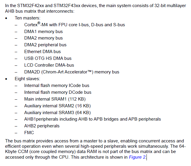
メモリの説明には256Kbyteと記載されているのに、メモリマップにはSRAM1~3で合計192Kbyteしかないのか?
SRAMとは別にCCMという、CPUを介してのみアクセスできるRAMが64Kbyteあり、それを含めた合計が256Kbyteという内容になっているため、アクセス可能なメモリは192Kbyteになっている。

参考にしたサイト


