今回は、arduinoIDEでino言語で開発してみた。
初めてのino開発であったが、簡略言語となっており、難易度はpythonと同程度だと思った。
つながっている間動くのは、ちょっと戸惑うが、先行事例が多いので比較的分かり易い。
今回も、このところやっているテーマと同じ、「追跡カメラを制御」する。
※ボードはRaspberry Picoはボードマネジャーに乗っているので、esp32,esp8266を以下の方法でインストールすれば、Arduino ボードと共に使えそうである。今回は格安なesp8266を利用した
やったこと
・arduinoIDEの構築
・esp8266との接続
・servoを動かす
・MPU9250センサーで9軸+1を測定する
・追跡カメラを制御する
・arduinoIDEの構築
開発環境は、windows10とRaspi上に構築した。
esp8266は、当初はパッケージに含まれていなかったので、以下の参考②の登録を実施して、windows上で開発した。
※esp32やesp8266ボードの登録は以下の参考②のとおり実施する必要がある
【参考】
①Arduino IDEのインストールと設定 (Windows, Mac, Linux対応)
②Installing ESP8266 Board in Arduino IDE (Windows, Mac OS X, Linux)
install手順
・ダウンロード
windows10;Win 7 and newerを選択
Raspi;ARM 32 bitsを選択
※just download選択だと課金なし
・解凍
windows10
ダウンロードしたarduino-xxx-windows.zipファイルを右クリックして「すべて展開」をクリックして解凍します。
その後、できたフォルダ内の「arduino.exe」をダブルクリックしてそのまま起動
Raspi
ファイラーが対応していれば右クリックから解凍
./install.sh
これで、Raspiのプログラミングに登録されます。
また、デスクトップに登録されました。
Install ESP8266 Add-on in Arduino IDE
1.In your Arduino IDE, go to File> Preferences
2. 以下の“Additional Boards Manager URLs” をarduinoIDE環境設定から追加する
URL間は,で区切る。
https://dl.espressif.com/dl/package_esp32_index.json,
http://arduino.esp8266.com/stable/package_esp8266com_index.json
3.ボードマネジャーでインストールする
ツール-ボード-ボードマネジャーを開き-esp8266などを入力し、インストールする。
これで、ボードから亜種が選択できるようになる。
・esp8266との接続
接続は以前と同様です。

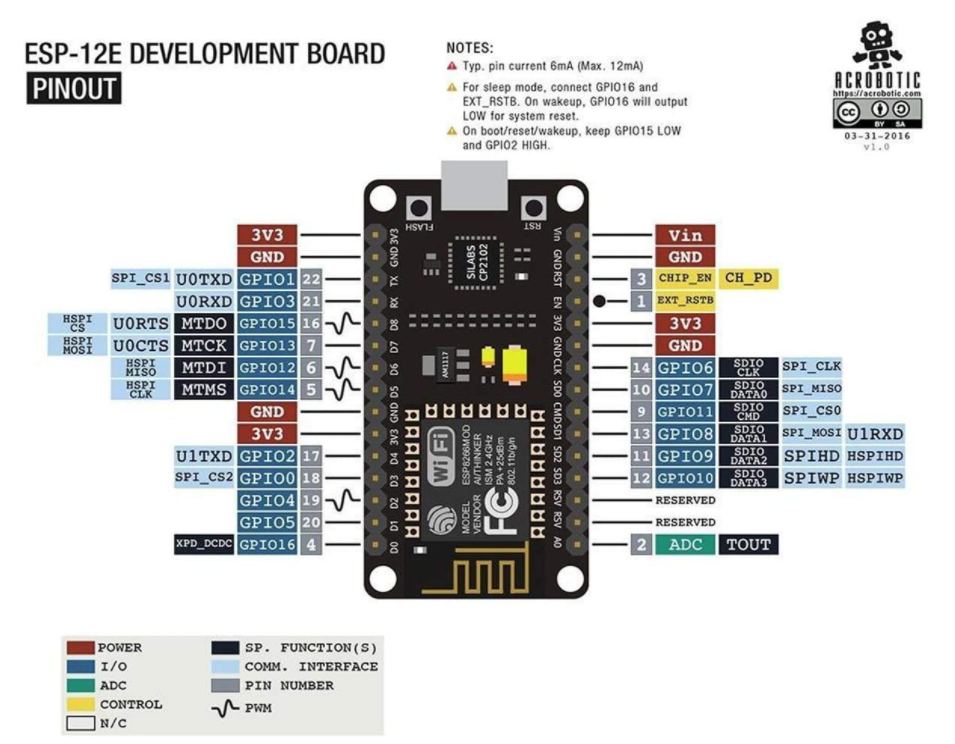
| esp8266 | mpu9250 | servo | Led |
|---|---|---|---|
| GND | GND | GND | GND |
| Pin(3.3v) | 3.3v | - | - |
| PILO(4.2v) | - | + | - |
| Pin(5) | SCL | - | - |
| Pin(4) | SDA | - | - |
| myservo1.attach(0) | - | Servo1(yellow) | - |
| myservo2.attach(12) | - | Servo2(yellow) | - |
| pinMode(14, OUTPUT) | - | - | led(+) |
・servoを動かす
以下のコードを見ると分かるが、最小限のコードで動くことが分かる。
大体、以下の参考のコードを拝借しています。
【参考】
③Arduinoを用いてサーボモータを制御する
servo_esp8266のコード
# include <Servo.h>          // サーボモータを動かすライブラリ
Servo myservo1;             //
Servo myservo2;             //

float power = 0;            // サーボの出力 sg90
int sk =0;

void setup() {
  Serial.begin(115200);     //シリアル通信を115200bpsに設定
  myservo1.attach(0);       // 0番ピンに接続
  myservo2.attach(12);       // 12番ピンに接続
  pinMode(14, OUTPUT);      // 14番ピンでLED(確認用)
}

void loop{
  // 出力を計算する
  power = sk*5%120; //制限があれば不要
  Serial.print(sk);
  power = constrain(power, 0, 120); // 角度制限

  Serial.print("power =\t");  Serial.print(power);  Serial.print("\n");
  myservo1.write(power); //servo1も2も同じだけ動かす
  myservo2.write(power);
  //以下はLチカ
  digitalWrite(14, HIGH);  // LED on
  delay(100);               // wait for 100 msec
  digitalWrite(14, LOW);    // LED off
  delay(100);
  sk += 1;
}
・MPU9250センサーで9軸+1を測定する
以下のコードで9軸+1軸測定できました。
大まかには、以下の参考の合体したコードになっています。
以前見たようにmpu9250とmpu6050のデータシートは地磁気を無視すれば同一なので、うまくいったようです。
※u2s関数は、micropythonで利用していたものの移植です。一応正しい数値が出ているようです
【参考】
④Arduinoで9軸センサー(加速度・ジャイロ・地磁気)を使ってみる
⑤Arduinoから MPU6050の値を取得してみる
mpu9250_esp8266のコード
# include "Wire.h"
int16_t axRaw, ayRaw, azRaw, gxRaw, gyRaw, gzRaw, Temperature;
float acc_x0=0, acc_y0=0, acc_z0=0;
float acc_x=0, acc_y=0, acc_z=0;
float gyro_x=0, gyro_y=0, gyro_z=0;
float mx_, my_, mz_;
int16_t mx,my,mz;
float temp;
int sk = 0;

void setup() {
  Wire.begin();
  Serial.begin(115200);
  setupMPU9250();
  readData();
  acc_x0=acc_x;
  acc_y0=acc_y;
  acc_z0=acc_z-1;
}

void loop() {
  readCompass();
  Serial.print(sk); Serial.print("\n");
  Serial.print("#magnetic#");
  Serial.print(mx_); Serial.print(",");
  Serial.print(my_); Serial.print(",");
  Serial.println(mz_);Serial.print("#accelerometer#");
  readData();
  Serial.print(acc_x-acc_x0); Serial.print(",");
  Serial.print(acc_y-acc_y0); Serial.print(",");
  Serial.println(acc_z-acc_z0);Serial.print("#gyroscope#");
  Serial.print(gyro_x);Serial.print(",");
  Serial.print(gyro_y); Serial.print(",");
  Serial.println(gyro_z);Serial.print("\n");
  delay(1000);
  sk += 1;
}

int16_t u2s(int16_t unsigneddata){
  int16_t usd = unsigneddata;
  if (usd & (0x01 << 15)){
      usd = -1 * ((unsigneddata ^ 0xffff) + 1);
  }
  return usd;
}

void readData() {
  Wire.beginTransmission(0x68);
  Wire.write(0x3B);
  Wire.endTransmission(false);
  Wire.requestFrom(0x68, 14, true);
  while (Wire.available() < 14);

  axRaw = u2s(Wire.read() << 8 | Wire.read());
  ayRaw = u2s(Wire.read() << 8 | Wire.read());
  azRaw = u2s(Wire.read() << 8 | Wire.read());
  Temperature = u2s(Wire.read() << 8 | Wire.read());
  gxRaw = u2s(Wire.read() << 8 | Wire.read());
  gyRaw = u2s(Wire.read() << 8 | Wire.read());
  gzRaw = u2s(Wire.read() << 8 | Wire.read());

  // 加速度値を分解能で割って加速度(G)に変換する
  acc_x = (2. / 32768.)*axRaw ;  //FS_SEL_0 16,384 LSB / g
  acc_y = (2. / 32768.)*ayRaw ;
  acc_z = (2. / 32768.)*azRaw ;

  // 角速度値を分解能で割って角速度(degrees per sec)に変換する
  gyro_x = (250. / 32768.)*gxRaw ;  // (度/s)
  gyro_y = (250. / 32768.)*gyRaw ;
  gyro_z = (250. / 32768.)*gzRaw ;
  //temperature
  temp= (Temperature-4040)/340. + 29.0; //室温29.0Cで校正
}

void readCompass() {
  float magcof = 4912/32760.0; //
  Wire.beginTransmission(0x0C);
  Wire.write(0x02);
  Wire.endTransmission();
  Wire.requestFrom(0x0C, 1);

  uint8_t ST1 = Wire.read();
  if (ST1 & 0x01) {
    Wire.beginTransmission(0x0C);
    Wire.write(0x03);
    Wire.endTransmission();
    Wire.requestFrom(0x0C, 7);
    uint8_t i = 0;
    uint8_t buf[7];
    while (Wire.available()) {
      buf[i++] = Wire.read();
    }
    if (!(buf[6] & 0x08)) {
      mx = ((int16_t)buf[1] << 8) | buf[0];
      my = ((int16_t)buf[3] << 8) | buf[2];
      mz = ((int16_t)buf[5] << 8) | buf[4];
      mx_ = mx*magcof;
      my_ = my*magcof;
      mz_ = mz*magcof;
    }
  }
}

//以下の数字の初期化の意味は参考③で解説されている
void setupMPU9250() {
  Wire.beginTransmission(0x68);
  Wire.write(0x6B);
  Wire.write(0x00);  // 0; 内部クロックを設定
  Wire.endTransmission();

  Wire.beginTransmission(0x68);
  Wire.write(0x1A);
  Wire.write(0x05);  //
  Wire.endTransmission();

  Wire.beginTransmission(0x68);
  Wire.write(0x37);
  Wire.write(0x02);
  Wire.endTransmission();

  Wire.beginTransmission(0x0C);
  Wire.write(0x0A);
  Wire.write(0x16);
  Wire.endTransmission();
  delay(500);
}
mpu9250_esp8266の出力例
1
# magnetic#47.53,-6.45,-7.95
# accelerometer#0.00,0.00,1.00
# gyroscope#0.77,-0.67,0.03

# Temperature#4089,29.14,
2
# magnetic#48.43,-6.75,-7.05
# accelerometer#-0.00,0.00,1.00
# gyroscope#0.73,-0.69,0.17

# Temperature#4089,29.14,
3
# magnetic#47.38,-6.00,-7.20
# accelerometer#0.00,0.00,1.00
# gyroscope#0.76,-0.66,0.08

# Temperature#4091,29.15,
4
# magnetic#49.03,-6.45,-7.65
# accelerometer#-0.00,0.00,1.00
# gyroscope#0.76,-0.63,-0.02

# Temperature#4091,29.15,
5
# magnetic#47.68,-6.60,-7.50
# accelerometer#-0.00,0.00,1.00
# gyroscope#0.72,-0.63,0.21

# Temperature#4096,29.16,
6
# magnetic#48.13,-6.15,-7.35
# accelerometer#-0.00,0.00,1.00
# gyroscope#0.77,-0.64,0.06

# Temperature#4101,29.18,
7
# magnetic#47.83,-5.85,-7.95
# accelerometer#-0.00,0.00,1.00
# gyroscope#0.75,-0.60,0.11

# Temperature#4098,29.17,
8
# magnetic#47.83,-6.15,-7.05
# accelerometer#0.00,0.00,1.00
# gyroscope#0.70,-0.63,0.15

# Temperature#4106,29.19,
9
# magnetic#48.13,-6.45,-7.65
# accelerometer#-0.01,-0.00,1.00
# gyroscope#0.79,-0.65,0.23

# Temperature#4104,29.19,
10
# magnetic#48.43,-6.45,-7.35
# accelerometer#-0.02,0.08,0.94
# gyroscope#7.70,0.37,-39.37

# Temperature#4111,29.21,
11
# magnetic#44.68,-6.90,-7.80
# accelerometer#0.01,0.01,1.01
# gyroscope#1.75,-3.44,-6.45

# Temperature#4113,29.21,
・追跡カメラを制御する
そして、追跡カメラの実装です。
ここで新たに追加したのは、void get_angle(){です。
この関数で、加速度とgyro_zから、pitchとyawを計算しています。
※関数の使い方が試行錯誤ですが、とりあえず以下で動きました
※何でもかんでも、global変数にしてしまいましたがご容赦ください
追跡カメラ_esp8266のコード
# include "Wire.h"
# include <Servo.h>          // サーボモータを動かすライブラリ
Servo myservo1;            //
Servo myservo2;
# define PI 3.141592653589793

float power1 = 0;            // サーボの出力 sg90
float power2 = 0;

int16_t axRaw, ayRaw, azRaw, gxRaw, gyRaw, gzRaw, Temperature;
float rawX, rawY, rawZ;
float acc_x0=0, acc_y0=0, acc_z0=0;
float acc_x=0, acc_y=0, acc_z=0;
float gyro_x=0, gyro_y=0, gyro_z=0;
float pitch, roll;
float gyro_z_=0;
int sk = 0;

void setup() {
  Serial.begin(115200);     //シリアル通信を115200bpsに設定
  myservo1.attach(0);       // 0番ピンに接続
  myservo2.attach(12);       // 12番ピンに接続
  pinMode(14, OUTPUT);      // 14番ピンでLED(確認用)

  Wire.begin();
  setupMPU9250();
  readData();
  acc_x0=acc_x;
  acc_y0=acc_y;
  acc_z0=acc_z-1;
}

void loop() {
  readData();
  Serial.println("#accelerometer#");
  Serial.print(acc_x-acc_x0); Serial.print(",");
  Serial.print(acc_y-acc_y0); Serial.print(",");
  Serial.print(acc_z-acc_z0);Serial.print("\n");
  Serial.print("#gyroscope#");
  Serial.print(gyro_x);Serial.print(",");
  Serial.print(gyro_y); Serial.print(",");
  Serial.print(gyro_z);Serial.print("\n");

  // 出力を計算する
  get_angle();
  gyro_z_ += gyro_z;
  Serial.print(pitch); Serial.print(",");
  Serial.print(roll); Serial.print(",");
  Serial.println(gyro_z_);Serial.print("\n");

  power2 = pitch;
  power1 = gyro_z_;
  Serial.print(sk); Serial.print("\n");
  //power1 = constrain(power1, -120, 120);  // 制限
  //power2 = constrain(power2, -120, 120);  // 制限
  //
  Serial.print("power1 =\t");  Serial.print(power1);  Serial.print("\n");
  Serial.print("power2 =\t");  Serial.print(power2); Serial.print("\n");
  myservo1.write(50-power1);
  myservo2.write(50-power2);

  digitalWrite(14, HIGH);
  delay(1000);
  digitalWrite(14, LOW);
  delay(1000);
  sk += 1;
}

void get_angle(){
  rawX = acc_x-acc_x0;
  rawY = acc_y-acc_y0;
  rawZ = acc_z-acc_z0;
  pitch = atan2(rawX, sqrt(rawY*rawY+rawZ*rawZ))* 180.0 / PI;
  roll = atan2(rawY, rawZ)* 180.0 / PI;
}

int16_t u2s(int16_t unsigneddata){
  int16_t usd = unsigneddata;
  if (usd & (0x01 << 15)){
      usd = -1 * ((unsigneddata ^ 0xffff) + 1);
  }
  return usd;
}

void readData() {
  Wire.beginTransmission(0x68);
  Wire.write(0x3B);
  Wire.endTransmission(false);
  Wire.requestFrom(0x68, 14, true);
  while (Wire.available() < 14);

  axRaw = u2s(Wire.read() << 8 | Wire.read());
  ayRaw = u2s(Wire.read() << 8 | Wire.read());
  azRaw = u2s(Wire.read() << 8 | Wire.read());
  Temperature = u2s(Wire.read() << 8 | Wire.read());
  gxRaw = u2s(Wire.read() << 8 | Wire.read());
  gyRaw = u2s(Wire.read() << 8 | Wire.read());
  gzRaw = u2s(Wire.read() << 8 | Wire.read());

  // 加速度値を分解能で割って加速度(G)に変換する
  acc_x = (2. / 32768.)*axRaw ;  //FS_SEL_0 16,384 LSB / g
  acc_y = (2. / 32768.)*ayRaw ;
  acc_z = (2. / 32768.)*azRaw ;

  // 角速度値を分解能で割って角速度(degrees per sec)に変換する
  gyro_x = (250. / 32768.)*gxRaw ;  // (度/s)
  gyro_y = (250. / 32768.)*gyRaw ;
  gyro_z = (250. / 32768.)*gzRaw ;
}

//初期化関数は、参考の解説みてください
void setupMPU9250() {
  Wire.beginTransmission(0x68);
  Wire.write(0x6B);
  Wire.write(0x00);
  Wire.endTransmission();

  Wire.beginTransmission(0x68);
  Wire.write(0x1A);
  Wire.write(0x05);
  Wire.endTransmission();

  Wire.beginTransmission(0x68);
  Wire.write(0x37);
  Wire.write(0x02);
  Wire.endTransmission();

  Wire.beginTransmission(0x0C);
  Wire.write(0x0A);
  Wire.write(0x16);
  Wire.endTransmission();
  delay(500);
}
追跡カメラ_esp8266の出力例
27
power1 =	21.44
power2 =	1.13
# accelerometer#
0.01,-0.03,0.96
# gyroscope#0.66,-0.60,0.06
0.83,-1.53,21.50

28
power1 =	21.50
power2 =	0.83
# accelerometer#
0.03,-0.03,0.94
# gyroscope#0.67,-0.83,0.09
2.06,-1.69,21.59

29
power1 =	21.59
power2 =	2.06
# accelerometer#
-0.02,-0.03,0.97
# gyroscope#0.48,-0.52,0.67
-1.02,-1.81,22.26

30
power1 =	22.26
power2 =	-1.02
おまけ
ArduinoIDEのアプリは、スケッチと呼ばれており、以下のようなコードである。
ここでは、初歩の関数化とクラス化をまとめておきます。
Lチカ
ファイルースケッチ例ーbasic-BLINKを選ぶと、以下のようなプログラムが呼び出せる。
実行すると、esp8266のon board Ledを1秒おきに光らせることができる。
Lチカ_esp8266のコード
void setup() {
  // initialize digital pin LED_BUILTIN as an output.
  pinMode(LED_BUILTIN, OUTPUT);
}

// the loop function runs over and over again forever
void loop() {
  digitalWrite(LED_BUILTIN, HIGH);   // turn the LED on (HIGH is the voltage level)
  delay(1000);                       // wait for a second
  digitalWrite(LED_BUILTIN, LOW);    // turn the LED off by making the voltage LOW
  delay(1000);                       // wait for a second
}
Lチカ(関数化)_esp8266のコード
void setup() {
  // initialize digital pin LED_BUILTIN as an output.
  pinMode(LED_BUILTIN, OUTPUT);
}

// the loop function runs over and over again forever
void loop() {
  ledonoff(true, 100);
  ledonoff(false, 1000);
}

void ledonoff(boolean param1, int param2){
  digitalWrite(LED_BUILTIN, param1);
  delay(param2);
}
Lチカ(class化)_esp8266のコード
# include "LedController.h"

LedController ledCont = LedController(LED_BUILTIN);

void setup() {
}

void loop() {
  ledCont.on();
  delay(1000);
  ledCont.off();
  delay(100);
}
ooptest.inoの画面の右上の▼から新規タブで以下を作成します。
# ifndef LedController_h
# define LedController_h

class LedController {

  public:
    LedController(int pin);
    void on();
    void off();

  private:
    int m_ledPin;
};

# endif
書き換えも出来そうですが、コードまるまるで掲載させていただきます。
# include "Arduino.h"
# include "LedController.h"

LedController::LedController(int pin) {
  m_ledPin = pin;
  pinMode(m_ledPin, OUTPUT);
}

void LedController::on(void) {
  digitalWrite(m_ledPin, HIGH);
}

void LedController::off(void) {
  digitalWrite(m_ledPin, LOW);
}