この記事では本格的なPLCをRasberry Pi4で構築します。
ただ信号をピコピコするだけはなくかなり本気でやります。
この記事では以下の要素技術を組み合わせて
- Docker
- OpenPLC
- modbus
- Scada
以下の動画のような現場猫がヨシッするアプリケーションを作ります。
必要なもの
構築にあたって必要なものは以下のとおりです。
- Rasberry Pi4B
- SDカード
- SDカードアダプタ
- USBケーブル
- SDカードライタ
- USB充電器
- ブレッドボード
- LEDx1
- 抵抗220Ωx1
- タクトスイッチx1
これらはamazonで買ったarduinoキットのものを流用
- パソコン(動作環境ubuntu20.04 x86_64)
揃っているか確認してヨシッ!!しましょう。
Rasberry Pi側セットアップ
Rasberry Pi OS(32-bit)のインストール
Rasberry Pi4BにRasberry Pi OS(32-bit)をインストールします。
このサイト
を参考に、rpi-imagerを使ってSDカードにRaspberry Pi OS(32-bit)イメージを書き込みます。
書き込みにはRasberry Pi4BではなくPCを使います。(当たり前ですね。)
PCにrpi-imagerを以下のコマンドでインストールします。
sudo apt install rpi-imager
インストールが完了したらSDカードライタを介してSDカードをPCに接続して以下の手順を実行します。
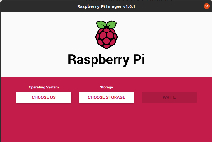
-
CHOOSE OS
Rasberry Pi OS(32-bit)を選択します。 -
CHOOSE STORAGE
接続したSDカードを選択します。 -
WRITE
このボタンで書き込みを開始。10分くらいかかります。
書き込みが終わったらSDカードの中身をファイルマネージャで開きます。
ssh(拡張子なし)という名前のファイルを小さい方のパーティションに配置しておきます。
これによりsshの接続ができるようになります。
その後、Rasberry PiにSDカードを差し込んで起動します。
この時、Rasberry Piにイーサネットケーブルを接続することを忘れないようにしてください。
起動が完了したらPCからラズベリーパイにssh接続します。以下のコマンドで接続できます。
ssh pi@<Rasberry Pi 4BのIPアドレス>
正常に接続するとパスワードが要求されます。パスワードはraspberryです。
Dockerのインストール
以下のリンクに従って以下のコマンドでRasberry Pi 4BにDockerをインストールできます。
sudo apt-get update && sudo apt-get upgrade
curl -sSL https://get.docker.com | sh
sudo usermod -aG docker pi
終わったら設定を有効化するためにRasberry Pi 4Bを再起動します。
docker-composeのインストール
docker-composeがあるだけでかなりRasberry Pi 4B上でDockerを実行するのが楽になります。
Rasberry Pi OS(32-bit)にはPython3がデフォルトでインスールされています。
なので、Rasberry Pi4B上で以下のコマンドを実行すれば一発でインストールできます。
sudo pip3 install docker-compose
PC側セットアップ
Dockerのインストール
PCにもDockerをインストールします。
Rasberry Piと同様に以下のコマンドで一発インスールできます。
sudo apt-get update && sudo apt-get upgrade
curl -sSL https://get.docker.com | sh
sudo usermod -aG docker <ユーザ名>
docker-composeのインストール
こちらもRasberry Pi 4Bと同じです。
以下のコマンドでインストールします。
sudo pip3 install docker-compose
OpenPLC設定・実行
Docker設定
Rasberry Piの適当なディレクトリに以下のファイルを配置しましょう。
- config.ini
- Dockerfile
- docker-compose.yml
それぞれのファイルに以下のように記述します。
; This configuration file enables configuring OpenPLC capabilities
; when the OpenPLC runtime starts. These capabilities can be configured
; without using the web front end and enable running the OpenPLC runtime
; standalone.
;
; This file must be located in the "etc" folder and must be named
; "config.ini".

; ---------------------------------------------------------
; ---------------------------------------------------------
[logging]

; Level defines the minimum level for a message to appear
; as a log message. Messages are a lower level are not
; output.
;
; Level may be one of the following values, ordered from
; lowest to highest:
;   trace, debug, info, warn, error
level = info

; ---------------------------------------------------------
; ---------------------------------------------------------
[interactive]
; The interactive server is what connects the web front end to the runtime
; You need this enabled if you want to be able to enable/disable services
; at runtime, view logs, etc.
;
; If you set this value to false and use the OpenPLC web interface to
; start the runtime, the web interface will not be able to communicate
; with the runtime.
enabled = true

; ---------------------------------------------------------
; ---------------------------------------------------------
[modbusslave]
; Modbus slave enables reading and writing located variables through the
; modbus interface. This starts a Modbus server (also know as a slave)
; running in the OpenPLC runtime.
enabled = true

; TCP Settings
; ------------
port = 502
address = 127.0.0.1

; How we bind located variables to modbus registers.
; This may be one of:
;   sized - indicates to use the size of a located variable to determine
;           the register type
binding = sized

; ---------------------------------------------------------
; ---------------------------------------------------------
[modbusmaster]
; Modbus master enables reading and writing located variables through the
; modbus interface. This starts capabilities to poll one or more Modbus
; servers and exchange data with the located variables.

enabled = false

; We support multiple Modbus masters. Each master should specify
; a complete set of configuration information within this section.
; Different masters are identified by a postfix which includes the
; index of the master. Indices start at 0 and go up from there.

; A user defined name for the connection. This name appears in log messages.
; name.0 = 1

; How long to wait for a response before indicating an error.
; Measured in microseconds.
; response_timeout.0 = 100000

; The rate at which to poll the server. Measured in microseconds.
; The actual poll rate may be greater than this depending on response times
; from the remote server and availability of resources on the local host.
; poll_interval.0 = 250000

; The protocol to use for connection. This value must be one of:
;   tcp
;   rtu
; If you set this to any other value, then this configuration item group
; is not created. You might use this to disable connecting to a particular
; Modbus slave.
; protocol.0 = tcp

; When there are communication failures, should we keep trying
; or backoff intelligently. The default behaviour is no backoff
; but you can specify one of the following:
;
;   none - Same as default, no strategy.
;   linear_bounded - Back off linearly based on the number of
;                    failed attempts. Bounded to 10x the poll
;                    interval.
; backoff_strategy.0 = linear_bounded

; slave_id.0 = 1
; ip_address.0 = 127.0.0.1
; ip_port.0 = 1000
; rtu_baud_rate.0 =
; rtu_parity.0 =
; rtu_data_bit.0 =
; rtu_stop_bit.0 =
; discrete_inputs_start.0 = 0
; discrete_inputs_size.0 = 1
; coils_start.0
; coils_size.0
; input_registers_start.0
; input_registers_size.0
; holding_registers_read_start.0
; holding_registers_read_size.0
; holding_registers_start.0
; holding_registers_size.0

; ---------------------------------------------------------
; ---------------------------------------------------------
[pstorage]
; The pstorage service reads and writes persistent storage. It enables
; the runtime to restore important variables to the previous value
; if the runtime is restarted.
enabled = false

; How long should we wait between write cycle. The persistent storage
; checks at this rate for changes and only persists to disk if a
; value has changed within the poll period
; poll_interval = 10
; poll_interval = 10

; ---------------------------------------------------------
; ---------------------------------------------------------
[dnp3s]
; The dnp3s enables a DNP3 outstation.
enabled = false

; Location Bindings
; -----------------

; Bind OpenPLC bit-sized output 0.0 to DNP3 binary input at index 0
; Note that the second hierarchical index must be 0
; bind_location = name:%QX0.0,group:1,index:0,

; Bind OpenPLC word-sized output 2 to DNP3 analog input at index 1
; bind_location = name:%QW2,group:30,index:1,

; Bind OpenPLC word-sized output 2 to DNP3 analog output status at index 1
; bind_location = name:%QW2,group:40,index:1,

; Bind OpenPLC long word-sized output 2 to DNP3 analog input at index 10
; bind_location = name:%QL2,group:30,index:10,

; Bind OpenPLC bit-sized input 0.0 to DNP3 analog input at index 10
; bind_location = name:%IX0.0,group:12,index:0,
; bind_location = name:%IX1.0,group:12,index:1,

; Bind OpenPLC word-sized input 2 to DNP3 analog command at index 0
; bind_location = name:%IW2,group:41,index:0,

; TCP Settings
; ------------
; address = 127.0.0.1
; port = 20000

; Link Settings
; -------------

; The remote and local address
; local_address = 10
; remote_address = 1

; Keep alive timeout. A value in seconds, or the keyword MAX
; keep_alive_timeout = MAX

; Parameters
; ----------

; Enable unsolicited reporting if master allows it
; enable_unsolicited = true

; How long (seconds) the outstation will allow a operate
; to follow a select
; select_timeout = 10

; max control commands for a single APDU
; max_controls_per_request = 16

; maximum fragment size the outstation will receive
; default is the max value
; max_rx_frag_size = 2048

; maximum fragment size the outstation will send if
; it needs to fragment. Default is the max falure
; max_tx_frag_size = 2048

; size of the event buffer
; event_buffer_size = 10

; Timeout for solicited confirms (milliseconds)
; sol_confirm_timeout = 5000

; Timeout for unsolicited confirms (milliseconds)
; unsol_confirm_timeout = 5000

; Timeout for unsolicited retries (milliseconds)
; unsol_retry_timeout = 5000

; The rate as which data is exchanged between DNP3 and the runtime
; (milliseconds)
; poll_interval = 250
FROM balenalib/raspberry-pi:latest

###########################################################################
# install dependency
###########################################################################
USER root
WORKDIR /root/
RUN apt-get update && apt-get upgrade -y
RUN DEBIAN_FRONTEND="noninteractive" apt-get -y install tzdata
RUN apt-get -y install autoconf automake bison build-essential cmake flex git libtool make pkg-config python3-pip python2.7 sqlite3 sudo wget
RUN wget https://project-downloads.drogon.net/wiringpi-latest.deb && sudo dpkg -i wiringpi-latest.deb
RUN pip3 install flask flask-login pyserial pymodbus
RUN sudo apt-get clean

###########################################################################
# install open plc
###########################################################################
# add openplc user
RUN useradd --create-home --shell /bin/bash openplc
RUN adduser openplc sudo && \
    echo '%sudo ALL=(ALL) NOPASSWD:ALL' >> /etc/sudoers
USER openplc
WORKDIR /home/openplc

# compile and install open plc
RUN git clone -b development https://github.com/thiagoralves/OpenPLC_v3.git
WORKDIR /home/openplc/OpenPLC_v3
RUN sudo ./install.sh rpi
COPY config.ini etc/config.ini

###########################################################################
# configure exposed ports
###########################################################################
# HTTP port
EXPOSE 8080/tcp
# Modbus port
EXPOSE 502/tcp
# DNP3 port
EXPOSE 20000/tcp
# EtherNet/IP port
EXPOSE 44818/tcp

###########################################################################
# configure entry point
###########################################################################
# USER openplc
USER openplc
WORKDIR /home/openplc/OpenPLC_v3
CMD ["sudo", "./start_openplc.sh"]
version: "3.9"
services:
  openplc:
    build: .
    ports:
      - "8080:8080"
      - "502:502"
      - "20000:20000"
      - "44818:44818"
      - "44628:44628"
    privileged: true
ファイルの配置が完了したらファイルがあるディレクトリで以下のコマンドを実行します。
sudo docker-compose build
Dockerイメージがビルドされます。
回路構築
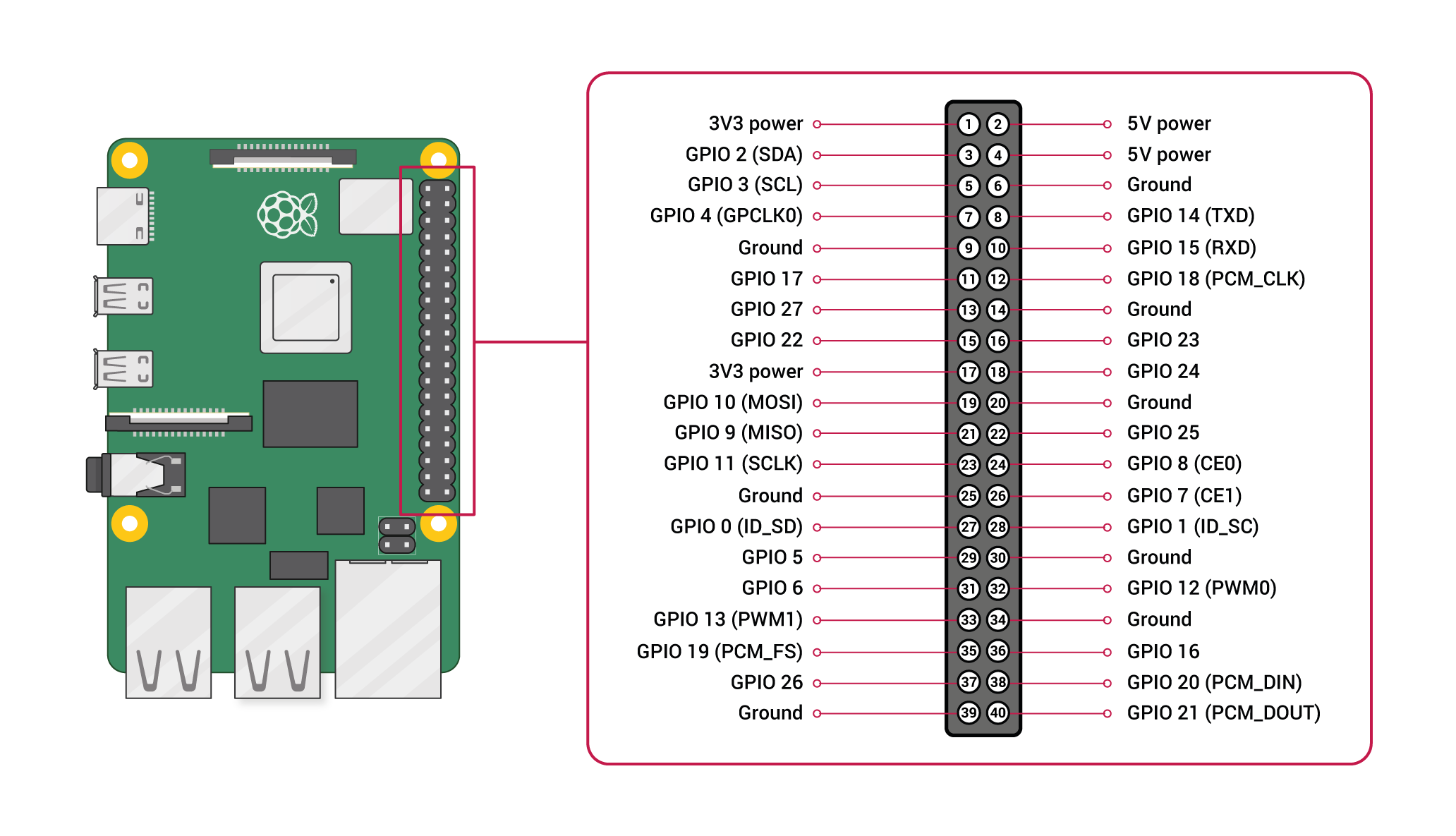
以下のようにLEDと220Ω抵抗、タクトスイッチを配線します。
- LED:220ΩとGPIO14
- 220Ω:LEDとグラウンド
- タクトスイッチ:GPIO17と3V3 poser
Rasberry Pi4Bのピン配置は以下のとおりです。
実行
Rasberry Pi 4Bのdocker-compose.ymlファイルがあるディレクトリで以下のコマンドを実行します。
sudo docker-compose up
コマンドを実行したらOpenPLCサーバ起動します。
FirefoxまたはChromeで<Rasberry Pi 4BのIP>:8080を開くと以下のログイン画面が表示されるはずです。
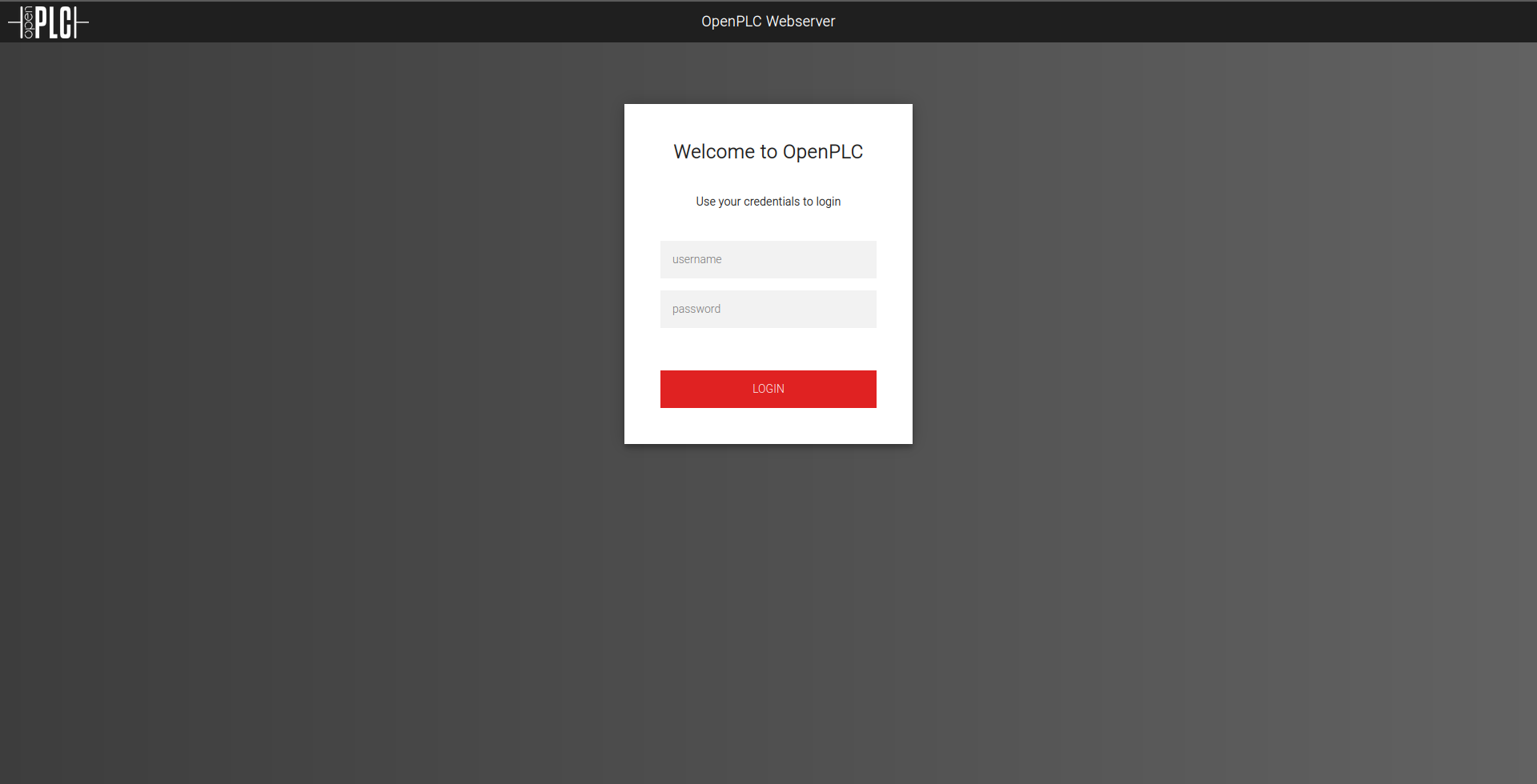
- username:openplc
- password:openplc
でログインします。
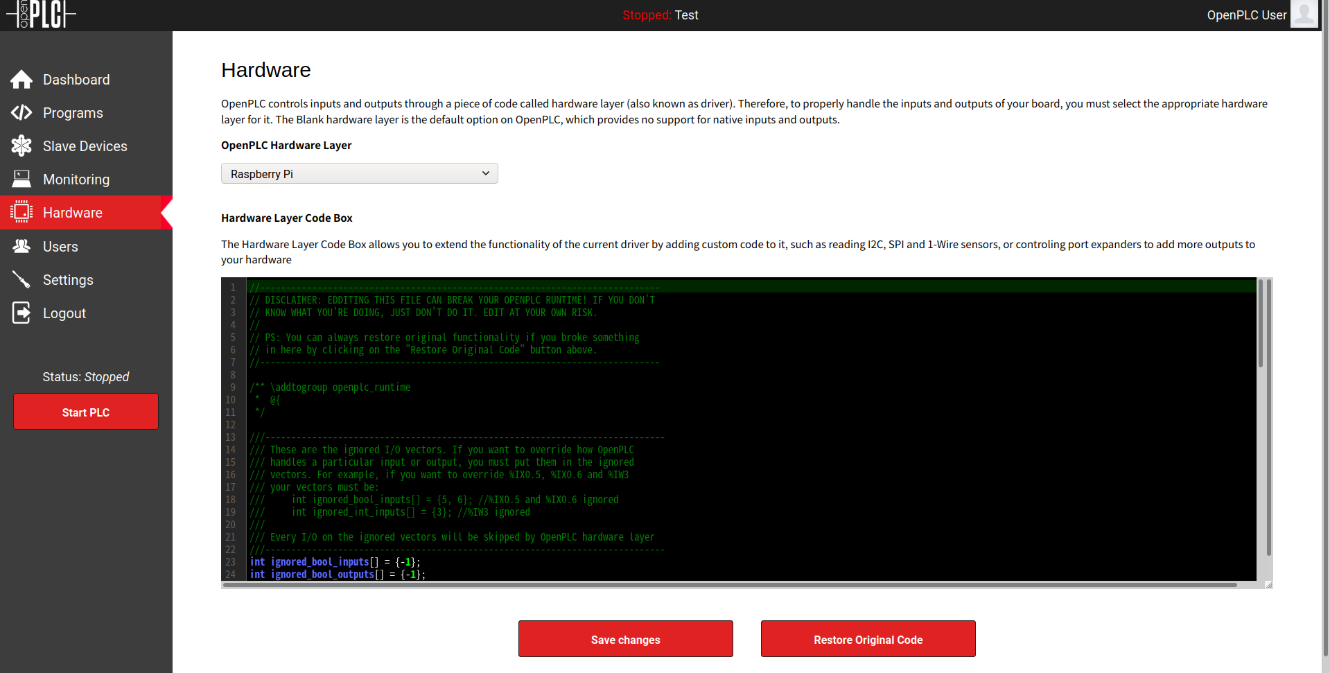
HardwareのページでRasberry Piを選択し、Save Changesボタンをクリックします。
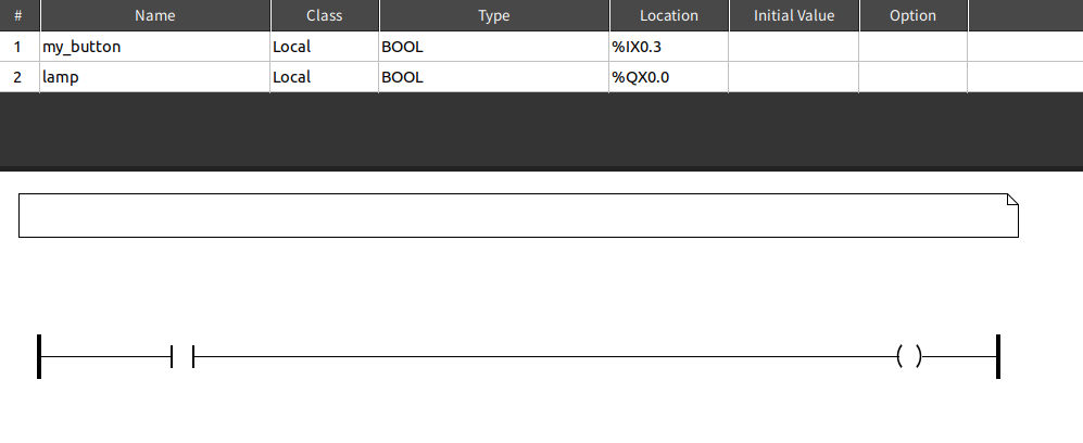
PC側で以下の内容のgenerated.stファイルを用意します。
PROGRAM Test
  VAR
    my_button AT %IX0.3 : BOOL;
    lamp AT %QX0.0 : BOOL;
  END_VAR

  lamp := my_button;
END_PROGRAM


CONFIGURATION Config0

  RESOURCE Res0 ON PLC
    TASK task0(INTERVAL := T#20ms,PRIORITY := 0);
    PROGRAM instance0 WITH task0 : Hello_World;
  END_RESOURCE
END_CONFIGURATION
このファイルはStructured Textという言語記載されています。
このファイルはOpenPLC Editorを使ってラダーを変換することで得ることができますが本記事ではOpenPLC Editorの使い方は割愛します。ちなみにもとのラダーは以下のようなラダーです。
※ Open PLC Editorのリンク
Programsタブを開きgenerated.stをアップロードし、コンパイルします。コンパイルに成功したらstart PLCでラダーを実行します。
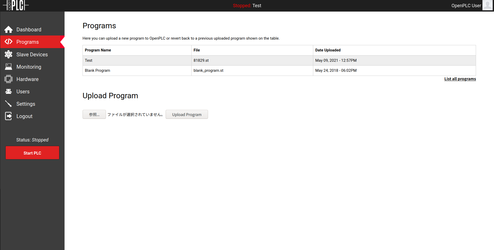
正しくラダーが実行されればタクトスイッチを押したときだけLEDが点灯するはずです。
PC側設定
ScadaBRイメージビルド&実行
PC側ではScadaBRをセットアップします。
ScadaBRではmodbus(通信プロトコル詳細は参考文献を参照)を介してRasberry Pi4Bの信号状態を取得します。
以下のように適当なディレクトリにDockerFile、docker-compose.ymlを配置します。
FROM ubuntu:latest

###########################################################################
# install dependency
###########################################################################
USER root
RUN apt-get update && apt-get upgrade -y
RUN DEBIAN_FRONTEND="noninteractive" apt-get install -y tzdata
RUN apt-get install -y git time sudo unzip

###########################################################################
# install scadadr
###########################################################################
RUN git clone https://github.com/thiagoralves/ScadaBR_Installer.git && \
    cd ScadaBR_Installer && \
    ./install_scadabr.sh
RUN /opt/tomcat6/apache-tomcat-6.0.53/bin/startup.sh && sleep 100
RUN cd ScadaBR_Installer && \
    ./update_scadabr.sh

###########################################################################
# Add Neko image
###########################################################################
COPY ./media/ /opt/tomcat6/apache-tomcat-6.0.53/webapps/ScadaBR/graphics/Neko/

###########################################################################
# configure exposed ports
###########################################################################
EXPOSE 8080
EXPOSE 502

###########################################################################
# configure command
###########################################################################
# Start the server
CMD /opt/tomcat6/apache-tomcat-6.0.53/bin/startup.sh && sleep infinity
version: "3.9"
services:
  scadabr:
    build: .
    ports:
      - "8080:9090"
      - "502:502"
    privileged: true
Dockerfileと同じ階層にmediaディレクトリを作成します。
mediaディレクトリには以下の2つの画像を配置します。


さらに画像と同じ階層にinfo.txtを配置します。
name=Neko
type=imageSet
# width=200
# height=200
text.x=14
text.y=2
Dockerfileのある階層で以下のコマンドを実行してDocker imageをビルドします。
sudo docker-compose build
ビルドがうまく行ったら次のコマンドでScadaBRを実行します。
sudo docker-compose up
ScadaBRの設定
FirefoxまたはChromeで<PCのIPアドレス>:8080/ScadaBR/にアクセスします。
以下のログイン画面が表示されるので
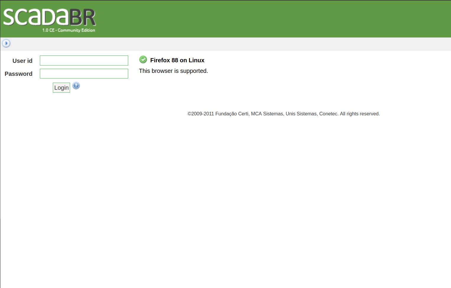
User id:admin
Password:admin
でログインします。
Data sourcesのタブからModbus IPのデータソースを追加します。
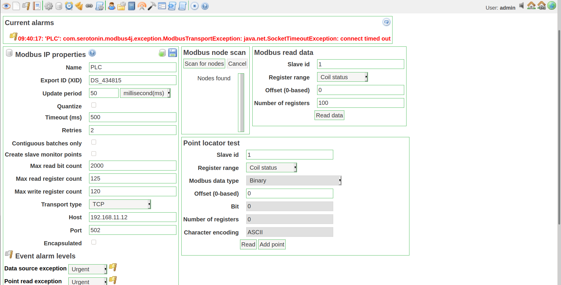
この時、Data SourceのIPにRasberry Pi 4BのIPアドレス。update periodに50 msecを指定し保存します。そして、Pointsを新規に追加し、Slaveに1。RangeにCoil status。Offsetに0を指定し保存します。保存が終わったら忘れずにData SourceとPointsをEnableにしておきましょう。
次にGraphic viewsタブを開きます。新たにGraphic viewsを追加します。ComponentsにBinary graphicをしていして追加します。追加したComponentのPointを先程追加したPointに指定。さらにgraphical rendererをNekoを指定します。
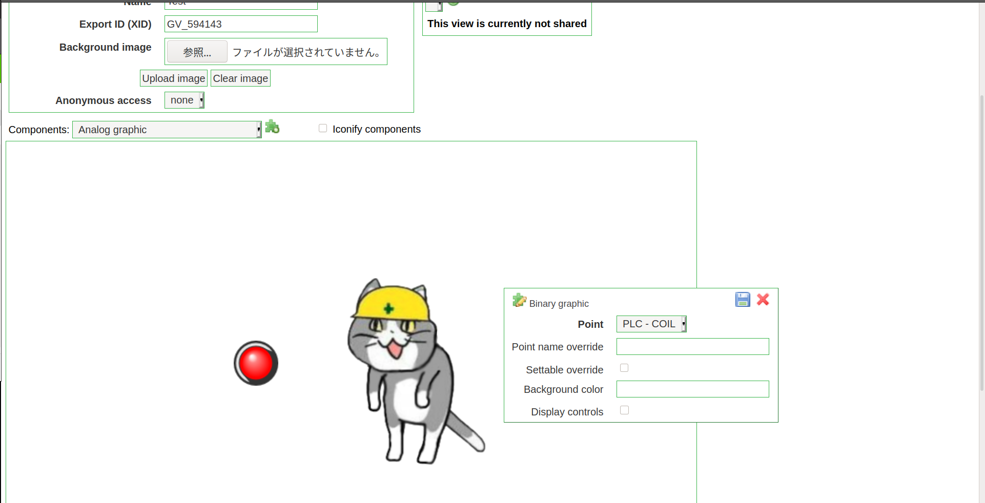
保存してFull Screenにすれば以下のように仕事猫が表示された画面になります。

タクトスイッチを押すとヨシッ!!します。