ATTiny85でI2Cスレーブが使えるようになったので、I2C赤外線リモコンを作ってみました。
回路
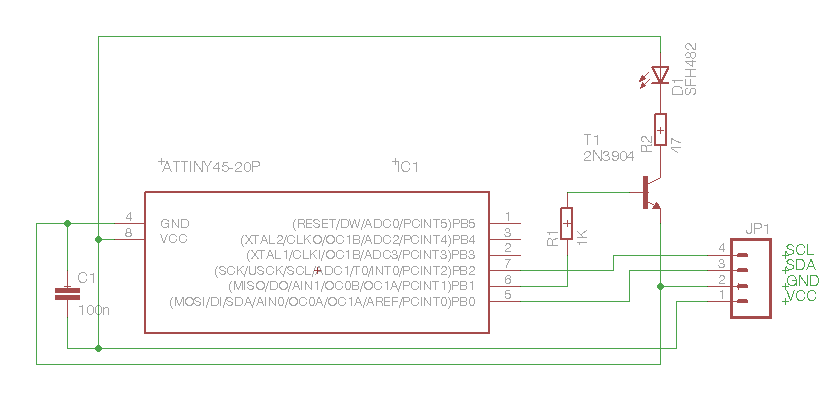
回路図の部品名などは適当です。実際にはこんな部品で作ってみました。
| 型番 | 数量 | 備考 |
|---|---|---|
| ATTiny85 | 1 | 秋月で160円 |
| OSI5FU5111C-40 | 1 | 赤外線LED |
| 2SC945 | 1 | 2SC1815でも可 |
| 0.1uF | 1 | セラミックコンデンサー |
| 100uF | 1 | 電解コンデンサー |
| 47Ω | 1 | |
| 1KΩ | 1 |
開発はArduino IDE 1.0.6にATTiny85などを追加した環境で、書き込みは自作のUSBtinyISPを使いました。
Timer1で38Kのキャリアを作りTimer0でI2Cで受け取ったデータのビットパターンをコントロールしています。I2Cのデータ形式はmruby-remocon同じで、SONYタイプのみの実装です。(1バイト目は上位4Bitが長さで、下位4ビットがタイプです。当初間違えていました。)
/* I2C IR remocon code
 * IR signal out put pin 6
 * 2018 Hiroki Mori
 */

/**
 * Pin notes by Suovula, see also http://hlt.media.mit.edu/?p=1229
 *
 * DIP and SOIC have same pinout, however the SOIC chips are much cheaper, especially if you buy more than 5 at a time
 * For nice breakout boards see https://github.com/rambo/attiny_boards
 *
 * Basically the arduino pin numbers map directly to the PORTB bit numbers.
 *
 * // I2C
 * arduino pin 0 = not(OC1A) = PORTB <- _BV(0) = SOIC pin 5 (I2C SDA, PWM)
 * arduino pin 2 =           = PORTB <- _BV(2) = SOIC pin 7 (I2C SCL, Analog 1)
 * // Timer1 -> PWM
 * arduino pin 1 =     OC1A  = PORTB <- _BV(1) = SOIC pin 6 (PWM)
 * arduino pin 3 = not(OC1B) = PORTB <- _BV(3) = SOIC pin 2 (Analog 3)
 * arduino pin 4 =     OC1B  = PORTB <- _BV(4) = SOIC pin 3 (Analog 2)
 */

# define I2C_SLAVE_ADDRESS 0x4 // the 7-bit address (remember to change this when adapting this example)

// Get this from https://github.com/rambo/TinyWire
# include <TinyWireS.h>

# define TWI_RX_BUFFER_SIZE  16

// effective plus 1 value
# define IR_REPEAT 3

int count;
int nextedge;
int curpos;

int irtype;
int irlen;
int repeat;

volatile uint8_t ir_data[TWI_RX_BUFFER_SIZE];

// TODO: Either update this to use something smarter for timing or remove it alltogether
void blinkn(uint8_t blinks)
{
    digitalWrite(3, HIGH);
    while(blinks--)
    {
        digitalWrite(3, LOW);
        tws_delay(50);
        digitalWrite(3, HIGH);
        tws_delay(100);
    }
}

void requestEvent()
{
  TinyWireS.send(0);
}

int getbit(int pos)
{
  int byte;
  int bit;

  byte = pos / 8;
  bit = pos % 8;

  return (ir_data[byte+1] >> (7 - bit)

  ) & 0x01;
}

int calcnext()
{
  int result;
  int val;
  if(curpos == 0)
    result = 4;
  else if(curpos == (irlen + 1) * 2 - 1)
    result = 50;
  else {
    val = getbit((curpos - 1) / 2);
    if((curpos % 2) == 0 && val) {
      result = 2;
    }
    else {
      result = 1;
    }
  }
  ++curpos;
  return result;
}

ISR(TIMER0_COMPA_vect)
{
  ++count;
  if (count == nextedge) {
    if(curpos / 2 == irlen + 1) {
      curpos = 0;
      count = 1;
      nextedge = 1;
      ++repeat;
    }
    if(curpos % 2 == 0) {
      // rising edge
      TCCR1 |= (1 << COM1A0);
    }
    else {
      // falling edge
      TCCR1 &= ~(1 << COM1A0);
    }
    nextedge += calcnext();
  }
  // stop
  if(curpos / 2 == irlen + 1) {
    if(repeat == IR_REPEAT) {
      TCCR0B = 0x00;
      TCCR1 &= ~(1 << COM1A0);
    }
  }
}

/**
 * The I2C data received -handler
 *
 * This needs to complete before the next incoming transaction (start, data, restart/stop) on the bus does
 * so be quick, set flags for long running tasks to be called from the mainloop instead of running them directly,
 */
void receiveEvent(uint8_t howMany)
{
  int i;

  if (howMany < 1)
  {
    // Sanity-check
    return;
  }
  if (howMany > TWI_RX_BUFFER_SIZE)
  {
    // Also insane number
    return;
  }

  i = 0;
  while(howMany--)
  {
    ir_data[i] = TinyWireS.receive();
    ++i;
  }
  irtype = ir_data[0] & 0x0f;
  irlen = (ir_data[0] >> 4) * 4;

  count = 0;
  nextedge = 1;
  curpos = 0;
  repeat = 0;

  // http://www.ernstc.dk/arduino/38khz_timer.htm
  // set up 38K carrier by timer1 but not output
  pinMode(1, OUTPUT);
  TCNT1 = 0;
  TCCR1 = 0;
  GTCCR |= (1 << PSR1); //section 13.3.2 reset the prescaler
  TCCR1 |= (1 << CTC1); // section 12.3.1 CTC mode
  //  TCCR1 |= (1 << COM1A0); //togle pin PB1 table 12-4
  TCCR1 |= (1 << CS10); //prescaler 1 table 12-5
  OCR1C = 104;
  OCR1A = 104;

  // set up timer0
  TCCR0A = 1 << 1;  // CTC
  TCCR0B = 0x03;   // 64 div
  TIMSK = (1 << OCIE0A);
  OCR0A = 0x4c;

  sei();
}


void setup()
{
  // TODO: Tri-state this and wait for input voltage to stabilize
  pinMode(3, OUTPUT); // OC1B-, Arduino pin 3, ADC
  digitalWrite(3, LOW); // Note that this makes the led turn on, it's wire this way to allow for the voltage sensing above.

  pinMode(1, OUTPUT); // OC1A, also The only HW-PWM -pin supported by the tiny core analogWrite

  /**
   * Reminder: taking care of pull-ups is the masters job
   */

  TinyWireS.begin(I2C_SLAVE_ADDRESS);
  TinyWireS.onReceive(receiveEvent);
  TinyWireS.onRequest(requestEvent);

  // Whatever other setup routines ?

  digitalWrite(3, HIGH);

}

void loop()
{

  /**
   * This is the only way we can detect stop condition (http://www.avrfreaks.net/index.php?name=PNphpBB2&file=viewtopic&p=984716&sid=82e9dc7299a8243b86cf7969dd41b5b5#984716)
   * it needs to be called in a very tight loop in order not to miss any (REMINDER: Do *not* use delay() anywhere, use tws_delay() instead).
   * It will call the function registered via TinyWireS.onReceive(); if there is data in the buffer on stop.
   */
  TinyWireS_stop_check();
}
当初Timer一本で作ろうとしたところ変な動きがあったので、二本使う事にしました。
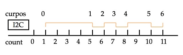
curposとcountの関係はこのようになっています。
テスト用のArduino(1.0.6)のコードはこのようにしました。
# include <Wire.h>

# define I2CADDR 4

void setup()
{
  Wire.begin();
}

void loop()
{
  Wire.beginTransmission(I2CADDR);
  Wire.write(0x33);
  Wire.write(0x4d);
  Wire.write(0x10);
  Wire.endTransmission();

  delay(1000);
}
EZ-USB FX2を使ったロジアナで見た信号はこのようになります。4回繰り返して出力します。>定数が3なのはおかしな動きがあったのでごめんなさい。
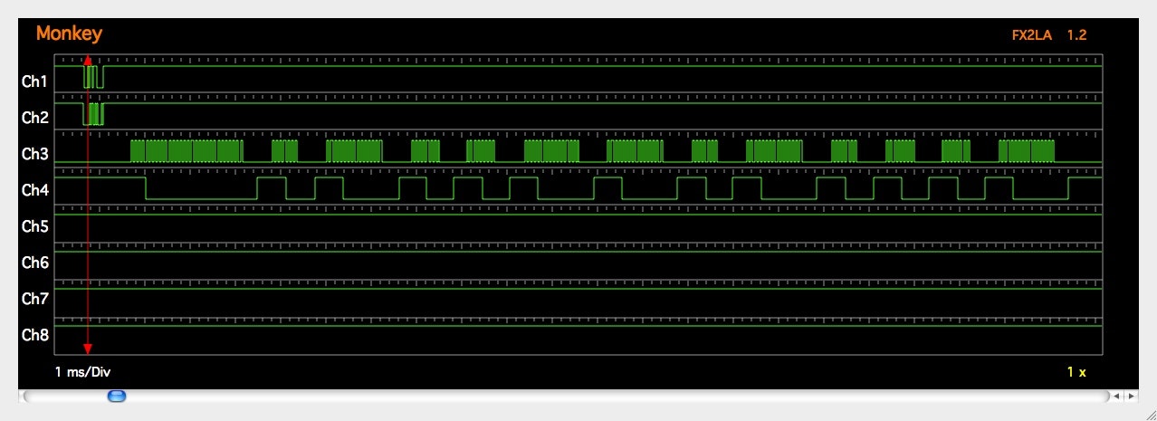
Ch1,Ch2がI2Cの信号でCh3が出力波形になります。Ch4は受信モニターの波形です。
ギアが壊れて再生できない30年前に買ったDISCMAN(12BIT信号)で試しましたがOCR0Aの設定が結構シビアな感じです。
I2Cは元々アナログテレビなどでリモコン信号を受信して処理する事などが主な使われ方でした。しかしI2Cの赤外線リモコン送信系はあまり目にしないので作ってみました。
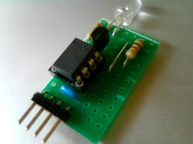
ブレッドボードからユニバーサル基板に移してみました。
NEC対応など追加した物をgithubで公開しました。
試してませんがDigisparkはTimer1を使っているようなので、動かないと思います。
ビルドすると3K弱なのでATTiny45でも入ると思います。
3.3Vと5Vの両方で使えます。
mruby-bsdiicでも使えるようにしてみました。
t = BsdIic.new(0)
t.writes(4, [0x33, 0x4d, 0x10])
処理してないときにはsleepするようにしました。スリープしないと待機時は7mAですが、スリープすると0.35mAくらいになりました。SLEEP_MODE_PWR_DOWNを指定しているので、もっと小さくなるような気もするのですが、何か止める必要があるんだろうか?