0. はじめに
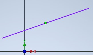
標準のスケッチコマンド、例えば一致コマンドでは、直線の中点を選択できます。

これをやりたい!!
1. 選択処理
一般的にInventorでは、SelectEventsを使って選択処理を行います。しかし、SketchLineには、中点のGeometoryがありません。
SelectEventsには様々なフィルターが設定できますが、やはりスケッチ中点を選択できるようなフィルターはありません。
では標準のコマンドはどうしているのでしょうか。恐らくは、直線の中点付近にマウスカーソルが来ると、自前で緑の丸を表示しているのです。
長らく緑丸を表示する(スマートな)方法が判らなかったのですが、この度ClientGraphicsを使えば表示できることがわかりました。
2. 直線上をホバーすると、中点を表示する
早速やってみました。
public InteractionEvents interactionEvents;   // これはOnExecuteでセットしてね

public void SelectEvents_OnPreSelect(
    ref object PreSelectEntity,
    out bool DoHighlight,
    ref ObjectCollection MorePreSelectEntities,
    SelectionDeviceEnum SelectionDevice,
    Point ModelPosition,
    Point2d ViewPosition,
    View View
    )
{
    DoHighlight = false;
    if (PreSelectEntity is SketchEntity sketchEntity)
    {
        if (sketchEntity is SketchLine line)
        {
            try
            {
                InteractionGraphics ig = interactionEvents.InteractionGraphics;
                ClientGraphics cg = ig.OverlayClientGraphics;

                if (cg.Count == 0)
                {
                    GraphicsNode gn = cg.AddNode(0);
                    PointGraphics pg = gn.AddPointGraphics();

                    // 点に座標を設定する
                    GraphicsCoordinateSet gcs = ig.GraphicsDataSets.CreateCoordinateSet(0);
                    Point2d midPoint2d = InventorApplication.TransientGeometry.CreatePoint2d();
                    Point midPoint = InventorApplication.TransientGeometry.CreatePoint();
                    midPoint2d.X = (line.StartSketchPoint.Geometry.X + line.EndSketchPoint.Geometry.X) / 2;
                    midPoint2d.Y = (line.StartSketchPoint.Geometry.Y + line.EndSketchPoint.Geometry.Y) / 2;
                    midPoint = (line.Parent as PlanarSketch).SketchToModelSpace(midPoint2d);

                    gcs.PutCoordinates(new double[3] { midPoint.X, midPoint.Y, midPoint.Z });
                    pg.CoordinateSet = gcs;

                    // 点の種類を選ぶ
                    pg.PointRenderStyle = PointRenderStyleEnum.kEndPointStyle;
                    // 常に前面に表示
                    pg.BurnThrough = true;  // 無視される。Inventorのbug?

                    // 表示を更新。これをしないと、表示されない。
                    ig.UpdateOverlayGraphics(View);
                }
            }
            catch
            {
            }
        }
    }
    return;
}
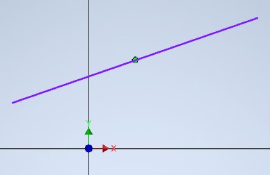
結果 (使いまわし画像じゃないよ)

中点が表示されました。点の種類は緑丸だけでなく、PointRenderStyleEnumから色々選べます。
以前にClientGraphicsを試した時は、デバッグ中にエラーで止まると描きかけの絵がDocumentに残ってしまい、とても面倒だった記憶があります。
しかし、InteractionEvents→InteractionGraphics→OverlayClientGraphicsから操作すると、InteractionEvents終了時には全て破棄されるので面倒ごとが起こりにくいです。
注意点として、AddNode()とCreateCoordinateSet()の引数ですが、これらは自分でユニークな数字になるよう管理する必要があります。
なお、上記コードでわざわざtry/catchしているのは、Autodesk Inventor API Hacking (だいたい一度はハマること)に書いたとおり、SketchLineには必ずしもStartSketchPoint,EndSketchPointがあるとは限らないので、念のためです。(雑すぎますけど)
3. bugかな?
上記の2枚の画像を良く比べると、2枚目は緑丸が直線に隠れているのが見て取れます。
サンプルコード中にコメントに書いた通り、どうやらBurnThroughの値は無視されるようです。ComponentDefinitionから作ったClientGraphicsなら期待通りに動くので、Inventorのbugかなと思います。現在、Autodesk Feedback Communityに問い合わせ中です。