VHDLでトリガーを生成する方法
ここでは,VHDLでトリガーを生成する方法を紹介したい.ただし,事前に,VHDLの簡単なシミュレーション方法(初学者向け) を読んで動かせていることが前提となります.
このでのトリガーとは,ある条件を満たすイベントが起こったと判定される事象で,その瞬間のちょっと前のデータから一定の長さのデータを保存することを目標とします.例えば, edge triggerを設定して,トリガーがかかったら 1024 サンプル分の波形を保存する,というような目的を想定しています.ここでは,シフトレジスタを使った簡単なトリガーシステムの紹介になります.
雷雲観測プロジェクトのGROWTH-DAQ (by湯浅くん) を参考にしています.
シフトレジスタのシミュレーション方法
レジスタとはデータを一時的に記憶するメモリのことです.シフトレジスタとは,記憶しているデータの桁を左右にシフトさせることができるレジスタのことです.これを使うと,例えば,A/D変換された信号を常に1ms分を保存しておくようなことが出来ます.具体的には,カメラで画像に変化がないか監視するシステムの場合,変化が起こったと判定されたときに,その瞬間からではなくて,その時点から1ms過去のデータから保存することができます.
コード
設定値などの共通パラメータ
定数(具体的には,AD/DAのbit数,delayの幅など)は,デバイスに依存して変わりうるので,ベタ書きしないで,C言語でいうヘッダーファイルに書き込んでおく.ここでは,次のような共通に使われるファイルを用いる.
library ieee, work;
use ieee.std_logic_1164.all;
use ieee.std_logic_arith.all;
use ieee.std_logic_unsigned.all;

package UserModule_LibrarySy1 is
  constant ADCResolution : integer := 14;      --10bit ADC
  constant WidthOfDepthOfDelay    : integer := 7;  --max depth=2^7=128
  constant MaximumOfDelay         : integer := 32;    --32clk delay
end UserModule_LibrarySy1;
シフトレジスタのVHDL
シフトレジスタの御本尊である.
冒頭の, use work.UserModule_LibrarySy1.all; の work は今いるディレクトリくらいの意味で,
python で言う所の, import UserModule_LibrarySy1 くらいのニュアンスです.
-- UserModule_ChModule_Delay.vhdl
-- Delay incoming ADC data

library ieee, work;
use ieee.std_logic_1164.all;
use ieee.std_logic_arith.all;
use ieee.std_logic_unsigned.all;
-- use work.iBus_Library.all;
-- use work.iBus_AddressMap.all;
--library IEEE;
--use IEEE.numeric_std.all;
use work.UserModule_LibrarySy1.all;

entity UserModule_ChModule_DelaySy1 is
  port(
    DepthOfDelay : in  std_logic_vector(WidthOfDepthOfDelay-1 downto 0);
    --
    AdcDataIn               : in  std_logic_vector(ADCResolution-1 downto 0);
    AdcDataOut              : out std_logic_vector(ADCResolution-1 downto 0);
    --clock and reset
    Clock                   : in  std_logic;
    GlobalReset             : in  std_logic
    );
end UserModule_ChModule_DelaySy1;

architecture Behavioral of UserModule_ChModule_DelaySy1 is

  --Signals
  signal Trigger        : std_logic                         := '0';
  signal a              : integer range 0 to MaximumOfDelay := 0;
  --Registers
  signal SampleRegister : std_logic_vector(15 downto 0)     := (others => '0');
  signal InputRegister  : std_logic_vector(15 downto 0)     := (others => '0');
  signal OutputRegister : std_logic_vector(15 downto 0)     := (others => '0');
  signal tmpAdcDataOut  : std_logic_vector(ADCResolution-1 downto 0); -- just for timing check

  type   AdcDataVector is array (integer range <>) of std_logic_vector(ADCResolution-1 downto 0);
  signal AdcDataArray : AdcDataVector(MaximumOfDelay downto 0) := (others=> (others=>'0'));

begin
  MainProcess : process (Clock, GlobalReset)
  begin
    tmpAdcDataOut <= AdcDataIn; -- just for timing check
    if (GlobalReset = '0') then
    elsif (Clock'event and Clock = '1') then
      -- Shift register
      AdcDataArray <= AdcDataArray(MaximumOfDelay-1 downto 0) & AdcDataIn;
      report "[S] AdcDataOut is updated";
      -- Select output
      if (a < MaximumOfDelay) then
        AdcDataOut <= AdcDataArray(a);
      end if;

      if (conv_integer(DepthOfDelay) < MaximumOfDelay) then
        a <= conv_integer(DepthOfDelay);
      else
        a <= 0;
      end if;
    end if;
  end process;

end Behavioral;
シフトレジスタをシミュレートするVHDLのテストベンチ
シミュレーションをする上では,クロックや,波形を自分で与える必要あります.また, debug がしやすいように,各所に report 文 (pythonで言うところのprint文) を入れて,中身をチェックします.
---------------------------------------------------
--Declarations of Libraries
---------------------------------------------------
library ieee, work;
use ieee.std_logic_1164.all;
use ieee.std_logic_arith.all;
use ieee.std_logic_unsigned.all;
--use ieee.numeric_std.ALL;
--use work.iBus_Library.all;
--use work.iBus_AddressMap.all;
use work.UserModule_LibrarySy1.all;

-- use std.env.finish;

entity sr_tb is
end sr_tb;

architecture sim of sr_tb is

  constant clock_period : time := 10 ns;

  -- Generics
  constant RAM_DEPTH : natural := 100000;

  -- from Library
  signal DepthOfDelay      : std_logic_vector(WidthOfDepthOfDelay-1 downto 0) := "0000011";

  -- DUT signals
  signal Clock : std_logic := '1';
  signal GlobalReset : std_logic := '1';
  signal AdcDataIn : std_logic_vector(ADCResolution - 1 downto 0) := (others => '0');
  signal AdcDataOut : std_logic_vector(ADCResolution - 1 downto 0):= (others => '0');

  signal counter : integer range RAM_DEPTH - 1 downto 0;

  component UserModule_ChModule_DelaySy1
    port(
      DepthOfDelay : in  std_logic_vector(WidthOfDepthOfDelay-1 downto 0);
      --
      AdcDataIn               : in  std_logic_vector(ADCResolution-1 downto 0);
      AdcDataOut              : out std_logic_vector(ADCResolution-1 downto 0);
      --clock and reset
      Clock                   : in  std_logic;
      GlobalReset             : in  std_logic
      );
  end component;


begin

  -- Process for generating the clock
  Clock <= not Clock after clock_period / 2;

  inst_DelayModule : UserModule_ChModule_DelaySy1
    port map(
      DepthOfDelay => DepthOfDelay,
      --
      AdcDataIn               => AdcDataIn,
      AdcDataOut              => AdcDataOut,
      --clock and reset
      Clock                   => Clock,
      GlobalReset             => GlobalReset
      );


  PROC_SEQUENCER : process is
  begin
    report "[T] start";
    counter <= 0;
    GlobalReset <= '0';
    wait for 5 * clock_period;
--    wait until rising_edge(Clock);
    GlobalReset <= '1';
    wait for 2 * clock_period;

    report "[T] fill FIFO";
    -- Fill the FIFO
    while (counter < 100) loop
      AdcDataIn <= AdcDataIn + '1';
      wait until rising_edge(Clock);
      counter <= counter + 1;
    end loop;

    wait for 10 * clock_period;

    for i in 0 to AdcDataOut'LENGTH loop
        report "AdcDataOut("&integer'image(i)&") value is" & std_logic'image(AdcDataOut(i));
    end loop;

    report "[S] shift register = " & integer'image(conv_integer(unsigned((AdcDataIn))));
    report "[T] end FIFO";

    wait for 5 * clock_period;
  assert (false) report "Simulation End!" severity failure;
--      finish;
  end process;

end architecture;
std_logic_vector を一気に report 文で1発で出力はできないようで,
    for i in 0 to AdcDataOut'LENGTH loop
        report "AdcDataOut("&integer'image(i)&") value is" & std_logic'image(AdcDataOut(i));
    end loop;
というように for loop を回して,一つずつ出力しています.
コンパイル
UserModule_LibrarySy1.vhdl がヘッダーファイルのようにみんなが参照するので,これを真っ先にコンパイルする.他は通常通りでOKです.
# !/bin/sh
ghdl -a --ieee=synopsys UserModule_LibrarySy1.vhdl
ghdl -a --ieee=synopsys UserModule_ChannelModule_DelaySy1.vhdl
ghdl -a --ieee=synopsys sr_tb.vhd
ghdl -e --ieee=synopsys sr_tb
ghdl -r --ieee=synopsys sr_tb --vcd=sr_tb.vcd
動作の概念図
動作の概念図としては,
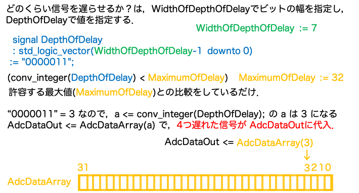
のような感じです. AdcDataArray がシフトしたデータを蓄積するレジスタになっていて,遅れた情報はここにたまる.例えば,う~んと長い情報を貯めためたければ,AdcDataArrayを長くすればよい. DepthOfDelayで指定した分だけ遅れた情報が取得できるので,これを調整することで,delayの長さを可変にできる.
実行結果
左のパネルから,トップモジュールと下位モジュールの全ての変数を選択して,出力させる.
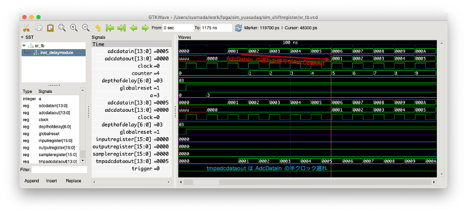
adcdataout は, adcdatain から少し遅れてデータが流れていることを確認しよう. tmpadcdataout は, process 分の動作チェック用につけただけ.これは半クロック遅れて更新されている.
トリガーをかける方法
コード
ヘッダーファイル
みやすさのために,Delayの深さを変えただけ.
---------------------------------------------------
--Declarations of Libraries
---------------------------------------------------
library ieee, work;
use ieee.std_logic_1164.all;
use ieee.std_logic_arith.all;
use ieee.std_logic_unsigned.all;

---------------------------------------------------
--Package for UserModules
---------------------------------------------------
package UserModule_LibrarySy1 is

  ---------------------------------------------------
  --Global variables
  ---------------------------------------------------
  constant ADCResolution : integer := 14;      --10bit ADC
  constant WidthOfDepthOfDelay    : integer := 7;  --max depth=2^7=128
  constant MaximumOfDelay         : integer := 1024;    --32clk delay

end UserModule_LibrarySy1;
Delay信号の生成
上の例と違って,みやすさのために,結構大きなdelayをさせるようにパラメータを微調整しただけ.
-- UserModule_ChModule_Delay.vhdl
-- Delay incoming ADC data

library ieee, work;
use ieee.std_logic_1164.all;
use ieee.std_logic_arith.all;
use ieee.std_logic_unsigned.all;
-- use work.iBus_Library.all;
-- use work.iBus_AddressMap.all;
--library IEEE;
--use IEEE.numeric_std.all;
use work.UserModule_LibrarySy1.all;

entity UserModule_ChModule_DelaySy1 is
  port(
    DepthOfDelay : in  std_logic_vector(WidthOfDepthOfDelay-1 downto 0);
    --
    AdcDataIn               : in  std_logic_vector(ADCResolution-1 downto 0);
    AdcDataOut              : out std_logic_vector(ADCResolution-1 downto 0);
    --clock and reset
    Clock                   : in  std_logic;
    GlobalReset             : in  std_logic
    );
end UserModule_ChModule_DelaySy1;

architecture Behavioral of UserModule_ChModule_DelaySy1 is

  --Signals
  signal Trigger        : std_logic                         := '0';
  signal a              : integer range 0 to MaximumOfDelay := 0;
  --Registers
  signal SampleRegister : std_logic_vector(15 downto 0)     := (others => '0');
  signal InputRegister  : std_logic_vector(15 downto 0)     := (others => '0');
  signal OutputRegister : std_logic_vector(15 downto 0)     := (others => '0');
  signal tmpAdcDataOut  : std_logic_vector(ADCResolution-1 downto 0); -- just for timing check

  type   AdcDataVector is array (integer range <>) of std_logic_vector(ADCResolution-1 downto 0);
  signal AdcDataArray : AdcDataVector(MaximumOfDelay downto 0) := (others=> (others=>'0'));

begin

  MainProcess : process (Clock, GlobalReset)
  begin

    tmpAdcDataOut <= AdcDataIn; -- just for timing check

    if (GlobalReset = '0') then
    elsif (Clock'event and Clock = '1') then
      -- Shift register
      AdcDataArray <= AdcDataArray(MaximumOfDelay-1 downto 0) & AdcDataIn;
--      report "[S] AdcDataOut is updated";

      -- Select output
      if (a < MaximumOfDelay) then
        AdcDataOut <= AdcDataArray(a);
      end if;

      if (conv_integer(DepthOfDelay) < MaximumOfDelay) then
        a <= conv_integer(DepthOfDelay);
      else
        a <= 0;
      end if;

    end if;

  end process;
end Behavioral;
トリガーの生成
単純なレベルトリガーの例です. state machine としては, Idle と Triggered を行き来するだけです.
トリガーがかかったら 1024 sample を delay した信号から出力する.
library ieee, work;
use ieee.std_logic_1164.all;
use ieee.std_logic_arith.all;
use ieee.std_logic_unsigned.all;
use work.UserModule_LibrarySy1.all;

entity UserModule_ChModule_TrigSy1 is
  generic (
    recordlength: integer := 10
    );
  port(
    AdcDataIn               : in  std_logic_vector(ADCResolution-1 downto 0);
    AdcDataDelayed          : in  std_logic_vector(ADCResolution-1 downto 0);
    TrigDataOut             : out std_logic_vector(ADCResolution-1 downto 0);
    --clock and reset
    Clock                   : in  std_logic;
    GlobalReset             : in  std_logic
    );
end UserModule_ChModule_TrigSy1;

architecture Behavioral of UserModule_ChModule_TrigSy1 is

  --Signals
  signal Trigger        : std_logic                         := '0';
  signal Threshold : std_logic_vector(15 downto 0)          := x"0010";
  signal tcounter : integer range 9000 downto 0 := 0;

  type UserModule_StateMachine_State is
    (Initialize, Idle, Triggered);
  signal UserModule_state : UserModule_StateMachine_State := Initialize;

begin


  --UserModule main state machine
  MainProcess : process (Clock, GlobalReset)
    variable t, s: integer;
  begin
    --is this process invoked with GlobalReset?
    if (GlobalReset = '0') then
      UserModule_state <= Initialize;
      --is this process invoked with Clock Event?
    elsif (Clock'event and Clock = '1') then

    case UserModule_state is
    when Initialize => if Trigger = '0' then
         UserModule_state <= Idle;
         else
         UserModule_state <= Triggered;
        end if;

    when Idle => if Trigger = '0' then
         t := conv_integer(Threshold);
         s := conv_integer(AdcDataIn);
        if (s > t) then
          Trigger <= '1';
          UserModule_state <= Triggered;
          tcounter <= 0;
        else
          Trigger <= '0';
        end if;
         else
         UserModule_state <= Triggered;
        end if;

    when Triggered => if Trigger = '0' then
         UserModule_state <= Idle;
         else
         TrigDataOut <= AdcDataDelayed;
         tcounter <= tcounter + 1;
         if tcounter > recordlength then
         Trigger <= '0';
         tcounter <= 0;
         UserModule_state <= Idle;
         end if;
        end if;
    end case;

    end if;
  end process;
end Behavioral;
シミュレーション
ノコギリ波を適当に入力する.
---------------------------------------------------
--Declarations of Libraries
---------------------------------------------------
library ieee, work;
use ieee.std_logic_1164.all;
use ieee.std_logic_arith.all;
use ieee.std_logic_unsigned.all;
use work.UserModule_LibrarySy1.all;

entity srtrig_tb is
end srtrig_tb;

architecture sim of srtrig_tb is

  constant clock_period : time := 10 ns;

  -- Generics
  constant RAM_DEPTH : natural := 100000;

  -- from Library
  signal DepthOfDelay      : std_logic_vector(WidthOfDepthOfDelay-1 downto 0) := "1100000";

  -- DUT signals
  signal Clock : std_logic := '1';
  signal GlobalReset : std_logic := '1';
  signal AdcDataIn : std_logic_vector(ADCResolution - 1 downto 0) := (others => '0');
  signal AdcDataOut : std_logic_vector(ADCResolution - 1 downto 0):= (others => '0');
  signal TrigDataOut : std_logic_vector(ADCResolution - 1 downto 0):= (others => '0');

  signal counter : integer range RAM_DEPTH - 1 downto 0;

  component UserModule_ChModule_DelaySy1
    port(
      DepthOfDelay : in  std_logic_vector(WidthOfDepthOfDelay-1 downto 0);
      --
      AdcDataIn               : in  std_logic_vector(ADCResolution-1 downto 0);
      AdcDataOut              : out std_logic_vector(ADCResolution-1 downto 0);
      --clock and reset
      Clock                   : in  std_logic;
      GlobalReset             : in  std_logic
      );
  end component;

  component UserModule_ChModule_TrigSy1
    generic(
      recordlength : integer
      );
    port(
      AdcDataIn               : in  std_logic_vector(ADCResolution-1 downto 0);
      AdcDataDelayed          : in  std_logic_vector(ADCResolution-1 downto 0);
      TrigDataOut              : out std_logic_vector(ADCResolution-1 downto 0);
      --clock and reset
      Clock                   : in  std_logic;
      GlobalReset             : in  std_logic
      );
  end component;


begin

  -- Process for generating the clock
  Clock <= not Clock after clock_period / 2;

  inst_DelayModule : UserModule_ChModule_DelaySy1
    port map(
      DepthOfDelay => DepthOfDelay,
      --
      AdcDataIn               => AdcDataIn,
      AdcDataOut              => AdcDataOut,
      --clock and reset
      Clock                   => Clock,
      GlobalReset             => GlobalReset
      );

  inst_TrigModule : UserModule_ChModule_TrigSy1
    generic map(
      recordlength => 256
      )
    port map(
      AdcDataIn               => AdcDataIn,
      AdcDataDelayed          => AdcDataOut,
      TrigDataOut              => TrigDataOut,
      --clock and reset
      Clock                   => Clock,
      GlobalReset             => GlobalReset
      );


  PROC_SEQUENCER : process is
  begin
    report "[T] start";
    counter <= 0;
    GlobalReset <= '0';
    wait for 5 * clock_period;
--    wait until rising_edge(Clock);
    GlobalReset <= '1';
    wait for 2 * clock_period;

    report "[1] fill FIFO";
    -- Fill the FIFO
    while (counter < 100) loop
      AdcDataIn <= AdcDataIn + '1';
      wait until rising_edge(Clock);
      counter <= counter + 1;
    end loop;
    counter <= 0;
    AdcDataIn <= conv_std_logic_vector(0,AdcDataIn'LENGTH);

    wait for 400 * clock_period;

    report "[2] fill FIFO";

    while (counter < 150) loop
      AdcDataIn <= AdcDataIn + '1';
      wait until rising_edge(Clock);
      counter <= counter + 1;
    end loop;
    counter <= 0;

    AdcDataIn <= conv_std_logic_vector(0,AdcDataIn'LENGTH);

    wait for 300 * clock_period;

    report "[3] fill FIFO";


    while (counter < 130) loop
      AdcDataIn <= AdcDataIn + '1';
      wait until rising_edge(Clock);
      counter <= counter + 1;
    end loop;
    counter <= 0;

    AdcDataIn <= conv_std_logic_vector(0,AdcDataIn'LENGTH);
    wait for 400 * clock_period;

    report "[4] fill FIFO";

    while (counter < 120) loop
      AdcDataIn <= AdcDataIn + '1';
      wait until rising_edge(Clock);
      counter <= counter + 1;
    end loop;
    counter <= 0;

    report "[5] fill FIFO";

    wait for 10 * clock_period;

    for i in 0 to AdcDataOut'LENGTH loop
        report "AdcDataOut("&integer'image(i)&") value is" & std_logic'image(AdcDataOut(i));
    end loop;

    report "[S] shift register = " & integer'image(conv_integer(unsigned((AdcDataIn))));
    report "[T] end FIFO";

    wait for 5 * clock_period;
  assert (false) report "Simulation End!" severity failure;
--      finish;
  end process;
end architecture;
コンパイル方法
# !/bin/sh
ghdl -a --ieee=synopsys UserModule_LibrarySy1.vhdl
ghdl -a --ieee=synopsys UserModule_ChannelModule_DelaySy1.vhdl
ghdl -a --ieee=synopsys UserModule_ChannelModule_TrigSy1.vhdl
ghdl -a --ieee=synopsys srtrig_tb.vhd
ghdl -e --ieee=synopsys srtrig_tb
ghdl -r --ieee=synopsys srtrig_tb --vcd=srtrig_tb.vcd
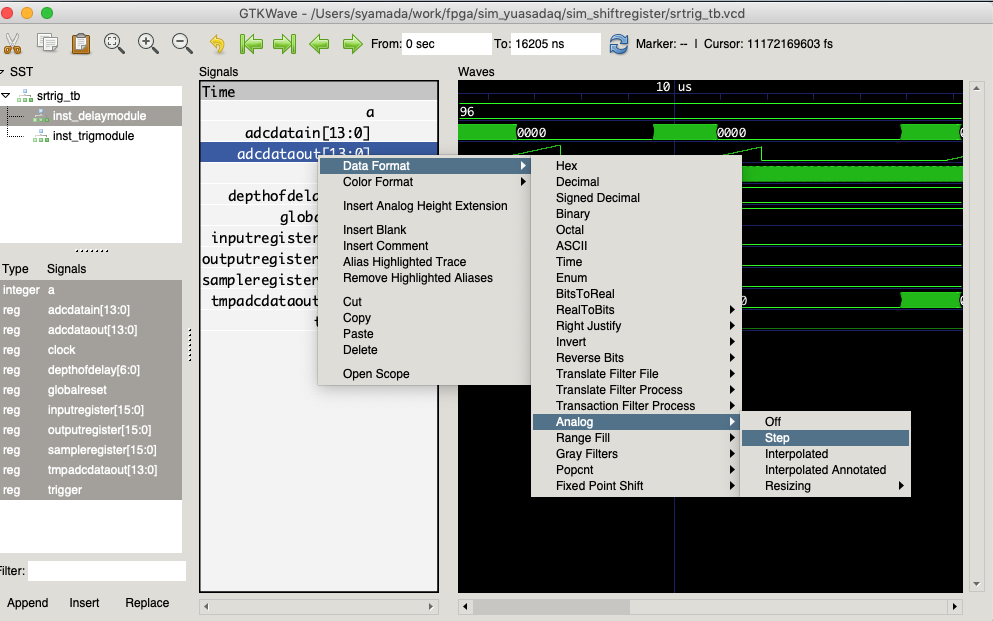
実行結果
ここで、表示をシグナルを選んで右クリックして、 Data Format ==> Analog ==> Step にすると、波形が見えるので、波形をみたい場合はアナログ表示にして確認してみよう。
調整すると、
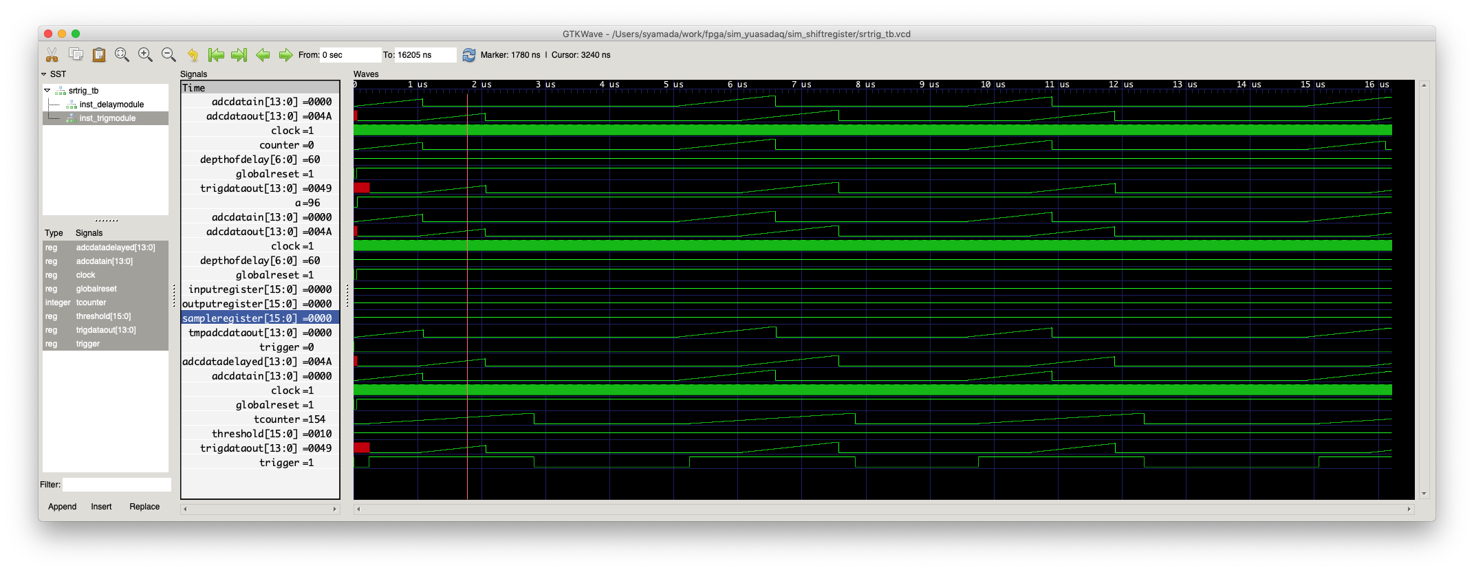
のように見えて、波形とそれが少しシフトしたものが見えているのが確認できる。