FPGAで波形生成
FPGAで波形を生成するには、いつくか方法ある。周期関数で周期を変更することをやりたい場合は、ROMに1周期分の波形をいれておいて、そのサンプリングを間引くことで早い周波数の波を生成される方法として、ダイレクトデジタルシンセサイザ (DDS) が知られている。ここでは、波形をROMにいれておいて、それを繰り返し再生するだけのシンプルなものを紹介する。
シミュレーションの方法は、VHDLの簡単なシミュレーション方法(初学者向け) を前提に記載してます。
python で波形生成
特に言語は何でもよいが、ここでは、sinを一周期分生成して、そのあとにゼロが続くような例を試すことにする。14bitのDA変換器をイメージして、振幅を13bitのちょっと小さいくらいの設定にしたがこれは何でも良い。
import numpy as np
import math
x = np.arange(60)
A = 2**13/4
y = A * np.sin(  (2*math.pi/60)*x)
x2 = np.zeros(150) # ゼロを150個加える
y2 = np.append(y,x2)
y2.astype(int) # VHDL用に整数にする
これでy2で生成した文字を下記のコードの signal sine : memory_type を作るのにコピペとかして使う。
VHDLのコード
生成した波形を integer と std_logic_vector の両方で持つような例を示す。シミュレーションの世界であれば interger でよいが、現実のAD/DA変換を扱う場合などは std_logic_vector にする場合が多いと思うので。
simplesine_tb.vhd
library ieee;
use ieee.std_logic_1164.all;
use ieee.std_logic_arith.all;
use ieee.std_logic_signed.all;
--use ieee.numeric_std.all;

entity simplesine_tb is
end entity;

architecture sim of simplesine_tb is

    constant ClockFrequency : integer := 1000e6; -- 1 GHz
    constant ClockPeriod    : time    := 1000 ms / ClockFrequency;

    constant MaxAdc : integer := 2**13; -- max bit of ADC
    constant Maxlen : integer := 210; -- length of buffer

    signal Clk : std_logic := '1';
    signal dataout : std_logic_vector(14 downto 0) := (others => '0');
    signal dataout_i : integer range -MaxAdc to MaxAdc :=0;

    signal i : integer range 0 to Maxlen:=0;

    type memory_type is array (0 to Maxlen-1) of integer range -MaxAdc to MaxAdc -1;
    --ROM for storing the sine values generated by python
    -- import numpy
    -- import math
    -- x = np.arange(60)
    -- A = 2**13/4 # 0.5 V
    -- y = A * np.sin( (2*math.pi/60)*x )
    -- x2 = np.zeros(150)
    -- y2 = np.append(y,x2)
    -- y2.astype(int)
    signal sine : memory_type := (
    	0,   214,   425,   632,   832,  1023,  1203,  1370,  1521,
        1656,  1773,  1870,  1947,  2003,  2036,  2048,  2036,  2003,
        1947,  1870,  1773,  1656,  1521,  1370,  1203,  1024,   832,
         632,   425,   214,     0,  -214,  -425,  -632,  -832, -1023,
       -1203, -1370, -1521, -1656, -1773, -1870, -1947, -2003, -2036,
       -2048, -2036, -2003, -1947, -1870, -1773, -1656, -1521, -1370,
       -1203, -1024,  -832,  -632,  -425,  -214,     0,     0,     0,
           0,     0,     0,     0,     0,     0,     0,     0,     0,
           0,     0,     0,     0,     0,     0,     0,     0,     0,
           0,     0,     0,     0,     0,     0,     0,     0,     0,
           0,     0,     0,     0,     0,     0,     0,     0,     0,
           0,     0,     0,     0,     0,     0,     0,     0,     0,
           0,     0,     0,     0,     0,     0,     0,     0,     0,
           0,     0,     0,     0,     0,     0,     0,     0,     0,
           0,     0,     0,     0,     0,     0,     0,     0,     0,
           0,     0,     0,     0,     0,     0,     0,     0,     0,
           0,     0,     0,     0,     0,     0,     0,     0,     0,
           0,     0,     0,     0,     0,     0,     0,     0,     0,
           0,     0,     0,     0,     0,     0,     0,     0,     0,
           0,     0,     0,     0,     0,     0,     0,     0,     0,
           0,     0,     0,     0,     0,     0,     0,     0,     0,
           0,     0,     0,     0,     0,     0,     0,     0,     0,
           0,     0,     0,     0,     0,     0,     0,     0,     0,
           0,     0,     0);

begin
    -- Process for generating the clock
    Clk <= not Clk after ClockPeriod / 2;

    genwave : process(Clk)
    begin
      --to check the rising edge of the clock signal
    if(rising_edge(Clk)) then
        dataout <=  conv_std_logic_vector(sine(i),dataout'LENGTH);
        dataout_i <= sine(i);
        i <= i + 1;
        if(i = Maxlen-1) then
        i <= 0;
        end if;
    end if;
    end process;

    -- Testbench sequence
    clktest: process is
    begin
    	wait for 1000 ns;

        assert (false) report "Simulation End!" severity failure;
        wait;
    end process clktest;

end architecture;
コンパイル方法
compile.sh
# !/bin/sh
ghdl -a --ieee=synopsys simplesine_tb.vhd
ghdl -e --ieee=synopsys simplesine_tb
ghdl -r --ieee=synopsys simplesine_tb --vcd=simplesine_tb.vcd
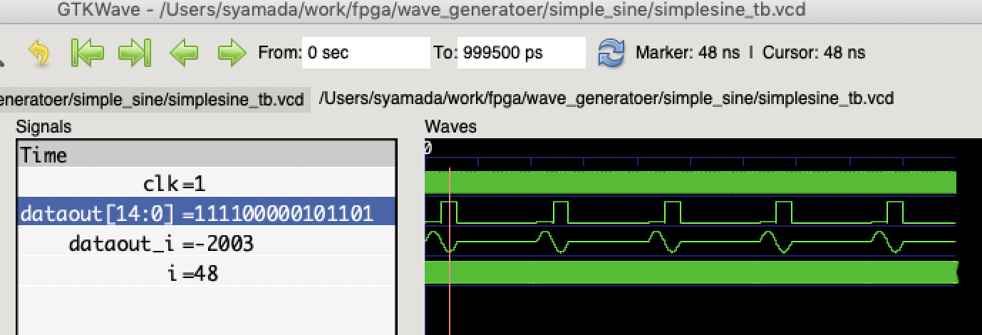
実行結果
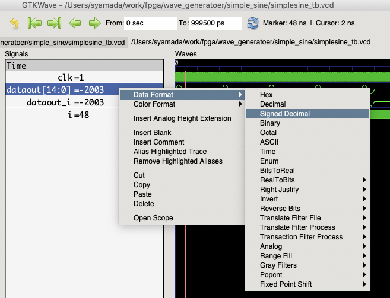
std_logic_vector の表示を Signed Desimal に変換
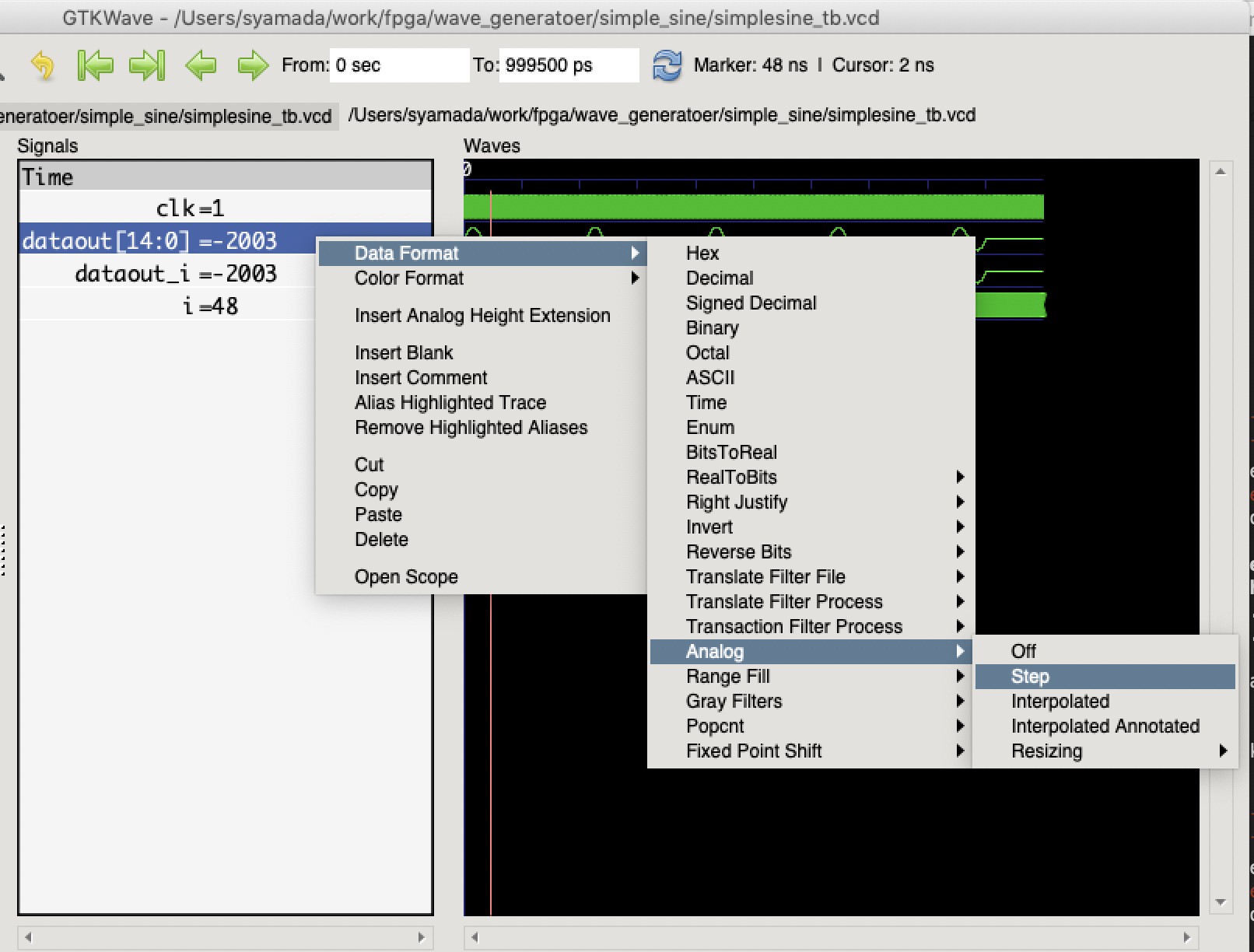
std_logic_vector の表示をAnalogに変換
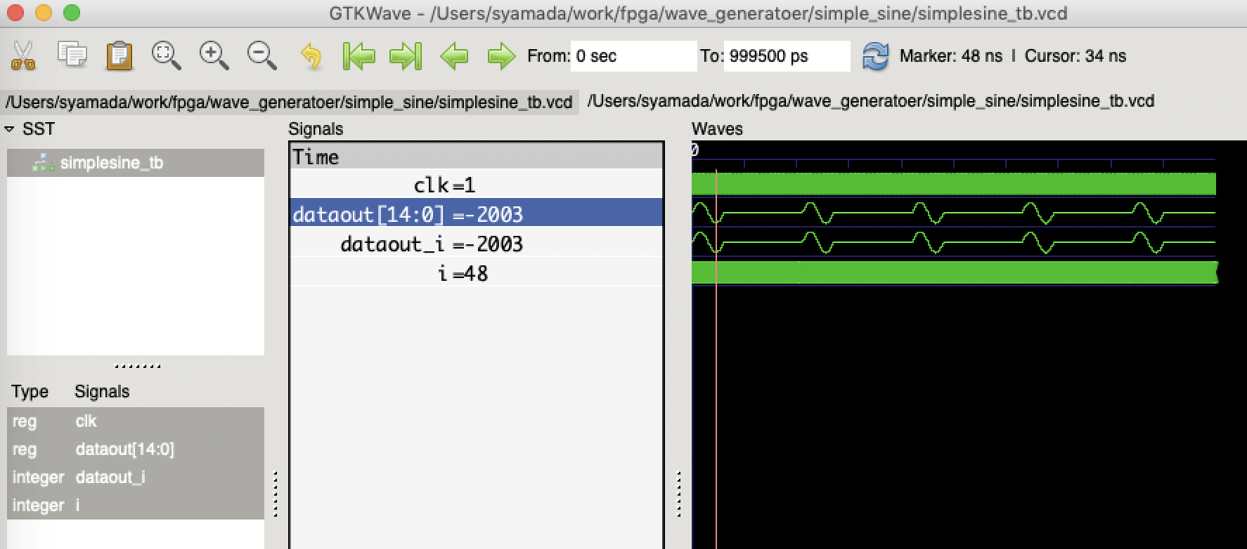
波形の確認
integer の表示も analog にすると、このような波形が見えるはず。
注意点
std_logic_vector の表示を binary にすると、パッと見で、全然違うように見える。これは負の数を2進数でどう表現するかということで、なんだっけっと思った人は、負の数(マイナスの数)は「補数」表現で を一読ください。signedを自作した変数をsingedで表示すれば問題ない。