Added May 2024.
A new feature has been added to VPC, which allows routing information to on-premises network to be advertised to PowerVS without having to create a prefix for the on-premises network.
Although the method described on this page works fine, I believe it will be easier to configure using this new functionality. The configuration procedure using the new feature is described below.
https://qiita.com/y_tama/items/592cc242299561128c55
Introduction
Power Systems Virtual Server (PowerVS) has VPNaaS service, but there are some limitations as described below.
https://cloud.ibm.com/docs/power-iaas?topic=power-iaas-VPN-connections
PowerVS VPNaaS has been deprecated.
In this article, I would like to consider how to access PowerVS using a site-to-site VPN that can be used in VPC, rather than PowerVS's VPNaaS.
The key points are as follows.
- If we configure it without thinking about anything special (what I will write in this article), PowerVS does not know the routing information to the on-premises IP address range, so it is not possible to send packets from PowerVS to the on-premises.
- This is the key to this configuration is to define the IP address range of the on-premises as the prefix of the VPC. This definition allows routing information for the on-premises IP range to be advertised to PowerVS via Cloud Connections (Direct Link 2.0) between the VPC and PowerVS, allowing PowerVS to send packets for the on-premises IP range to the VPC.
- Define an ingress routing table in the VPC so that packets from PowerVS to the VPC (destined for the on-premises IP) will be routed to the VPN Gateway.
- The VPN Gateway passes the packets to the on-premises through the VPN tunnel, enabling end-to-end communication.
Added January 2024.
The following Docs contains a connection configuration using the same concept as this article.
https://cloud.ibm.com/docs/power-iaas?topic=power-iaas-vpn-connectivity
An overview image is shown below.

Connecting on-premises and VPC with site-to-site VPN.
Connect on-premises and VPC with site-to-site VPN on VPC. Note that the VPN configuration on IBM Cloud side must be made with a policy based.
This configuration will not work if the VPN setting on the IBM Cloud side is route based.
For Local IBM CIDRs, specify the PowerVS subnet, not the VPC subnet.
For the Peer CIDRs, just specify the subnet of the on-premises as usual.
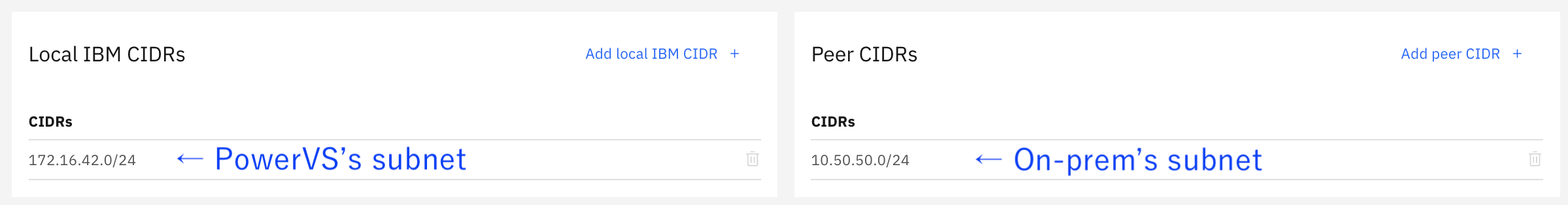
On the opposite on-premises VPN router, also specify the PowerVS subnet, not the VPC subnet, for the Peer CIDRs.
Create Cloud Connections in PowerVS
Create Cloud Connections (Direct Link 2.0) in PowerVS. In this case, we will create a Transit Gateway type.

If the LPAR has a Public IP, the default gateway is set to the public side. Configure static routes on the LPAR so that packets destined for on-premises are routed to the private-side gateway.
# netstat -r
Routing tables
Destination        Gateway           Flags   Refs     Use  If   Exp  Groups

Route tree for Protocol Family 2 (Internet):
default            192.168.179.25    UG        6   6207270 en0      -      -
10.50.50/24        172.16.42.1       UGS       0      1184 en1      -      -
127/8              localhost         U         4    945769 lo0      -      -
...
Connect Direct Link 2.0 from PowerVS to Transit Gateway.
Connect the Direct Link 2.0 from PowerVS created above to the Transit Gateway.


Define on-premise IP range as VPC prefix
This is a bit tricky, but it is the key to this configuration.
This definition allows routing information to the on-premises IP range to be advertised on the PowerVS side via Cloud Connections (Direct Link 2.0) between the VPC and PowerVS, allowing PowerVS to send packets to the on-premises IP address range to the VPC.
In this case, 10.50.50.0/24 is the on-premises IP address range, so we define it as the VPC prefix. (There is no need to create a subnet in the VPC corresponding to 10.50.50.0/24.)

Connect the VPC to the Transit Gateway

Checking the routing information, we can see that the route information is advertised from PowerVS and from the VPC.
Since we defined the on-premises IP address range (10.50.50.0/24 in this case) as a prefix in the VPC, that route information is also advertised from the VPC. This is advertised to PowerVS, so packets destined for 10.50.50.0/24 sent from PowerVS will reach the VPC.

Define ingress routing table on VPC
Next, define an ingress routing table so that packets destined for on-premises (10.50.50.0/24 in this case) arriving at the VPC from PowerVS will be sent to the VPN tunnel.
If the VPC does not already have an ingress route table, create one.
Select VPN gateway in Accepts routes from so that the route information configured at VPN Gateway is automatically reflected in the route table.
For Traffic source, select Transit Gateway in this case.
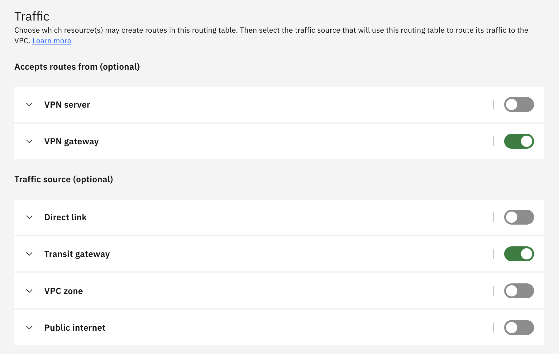
Ingress route table receives routing information from the VPN Gateway and automatically configures ingress route so that the next hop of packets destined for on-premises(IP address range defined as "Peer CIDR" in the policy-based VPN settings) is the VPN Gateway.
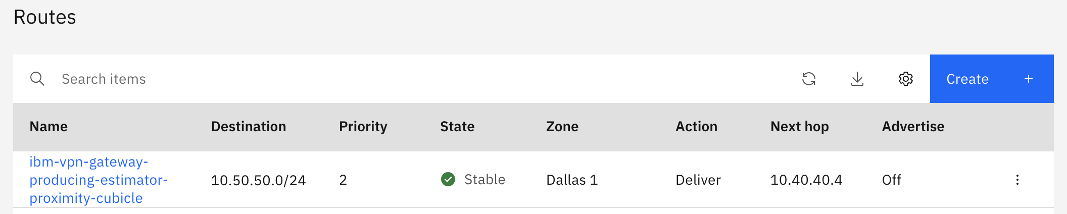
Once the packets reach the VPN Gateway, the VPN Gateway knows the route to the on-premises beyond, so it can deliver the packets to the on-premises through the VPN tunnel.
This enables communication from the on-premises to PowerVS.
Below is a ping from the on-premises server (10.50.50.6) to the PowerVS AIX (172.16.42.123).
[root@tamavsi01 ~]# ip a
1: lo: <LOOPBACK,UP,LOWER_UP> mtu 65536 qdisc noqueue state UNKNOWN group default qlen 1000
    link/loopback 00:00:00:00:00:00 brd 00:00:00:00:00:00
    inet 127.0.0.1/8 scope host lo
       valid_lft forever preferred_lft forever
    inet6 ::1/128 scope host
       valid_lft forever preferred_lft forever
2: eth0: <BROADCAST,MULTICAST,UP,LOWER_UP> mtu 1400 qdisc pfifo_fast state UP group default qlen 1000
    link/ether 02:00:06:11:ef:41 brd ff:ff:ff:ff:ff:ff
    inet 10.50.50.6/26 brd 10.50.50.63 scope global noprefixroute dynamic eth0
       valid_lft 235sec preferred_lft 235sec
    inet6 fe80::6ff:fe11:ef41/64 scope link
       valid_lft forever preferred_lft forever
[root@tamavsi01 ~]# ping 172.16.42.123
PING 172.16.42.123 (172.16.42.123) 56(84) bytes of data.
64 bytes from 172.16.42.123: icmp_seq=1 ttl=241 time=143 ms
64 bytes from 172.16.42.123: icmp_seq=2 ttl=241 time=155 ms
64 bytes from 172.16.42.123: icmp_seq=3 ttl=241 time=146 ms
64 bytes from 172.16.42.123: icmp_seq=4 ttl=241 time=143 ms
^C
--- 172.16.42.123 ping statistics ---
4 packets transmitted, 4 received, 0% packet loss, time 3003ms
rtt min/avg/max/mdev = 143.775/147.450/155.514/4.778 ms
[root@tamavsi01 ~]#