背景###
RetinaNetの原理の一つは画像を複数サイズの囲碁の碁盤に合わせて分割りする。分割りされたマスを中心にanchorboxを生成して、anchorboxを教師データground truthを目指して変形しようとします。
囲碁の碁盤のサイズがfeature pyramid layersから決められます。
本節は、決められた囲碁の碁盤のサイズに合わせて、anchorboxを生成する手順を紹介します。
流れ###
Pyramid Level####
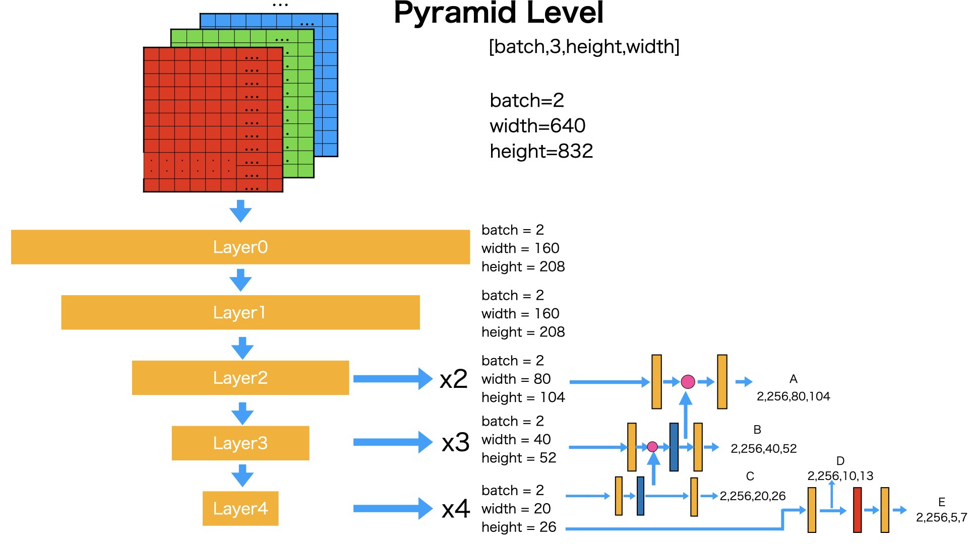
図のように、layer0からlayer4までの一連の流れを経由して、入力データがx2,x3,x4になります。
さらに、x2,x3,x4を入力として、feature pyramid layersに流します。出てきた結果は
A,B,C,D,Eになります
A,B,C,D,Eのサイズは5つ囲碁の碁盤のサイズを決めます。
ここでは
入力
2,3,640,832
出力
A:(2,256,80,104) -> 画像を(80,104)の碁盤に分割りします
B:(2,256,40,52) -> 画像を(40,52)の碁盤に分割りします
C:(2,256,20,26) -> 画像を(20,26)の碁盤に分割りします
D:(2,256,10,13) -> 画像を(10,13)の碁盤に分割りします
E:(2,256,5,7) -> 画像を(5,7)の碁盤に分割りします
RetinaNet構造によって、
Aのサイズは入力画像サイズの1/8になります ------ マスとマスのサイズは(8,8)
Bのサイズは入力画像サイズの1/16になります ------ マスとマスのサイズは(16,16)
Cのサイズは入力画像サイズの1/32になります ------ マスとマスのサイズは(32,32)
Dのサイズは入力画像サイズの1/64になります ------ マスとマスのサイズは(64,64)
Eのサイズは入力画像サイズの1/128になります ------ マスとマスのサイズは(128,128)
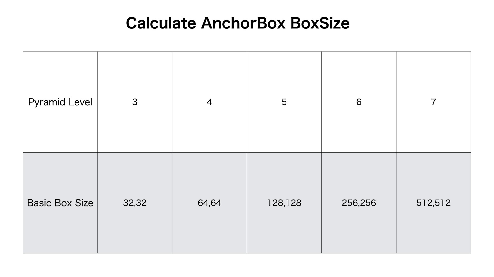
ここではpyramid levelの概念を引用します
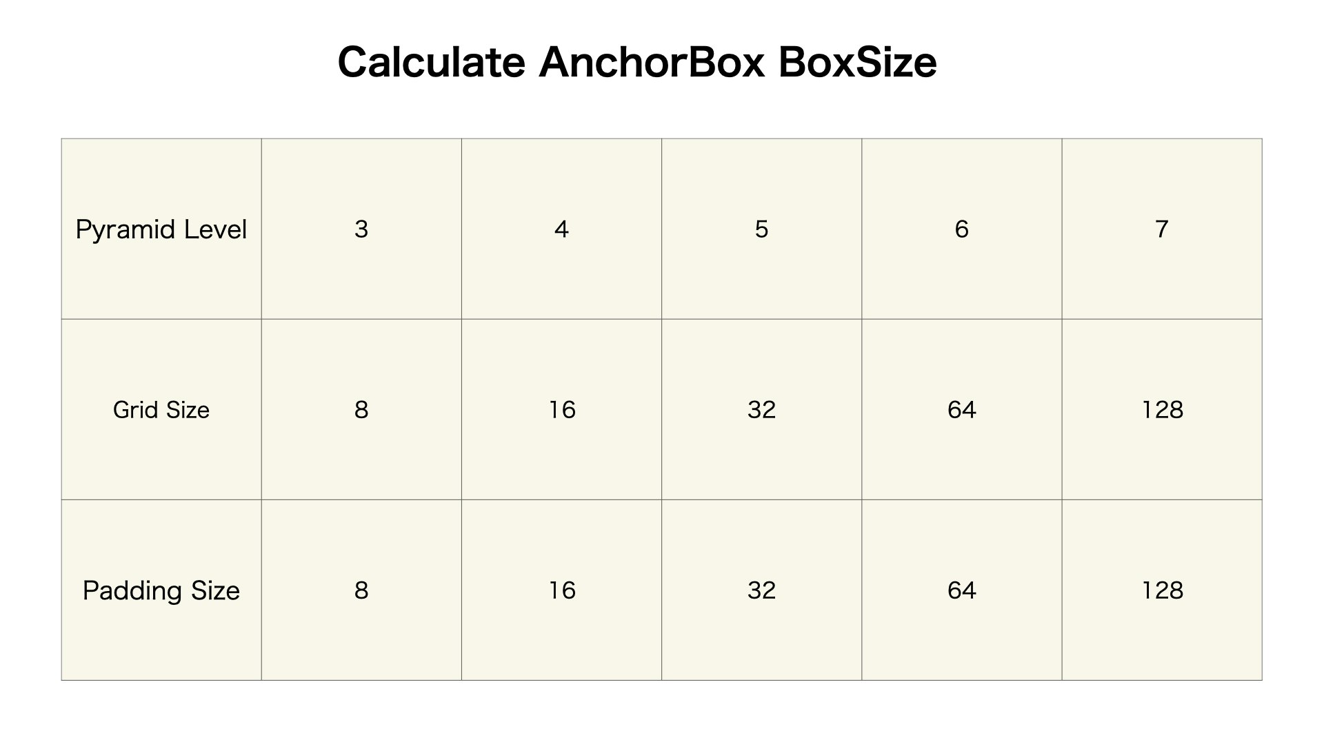
pyramid levelが3,4,5,6,7になります
囲碁の碁盤のサイズは画像サイズの1/2**(pyramid level)になります
囲碁の碁盤のマスのサイズは2**(pyramid level)になります
囲碁の碁盤のマスとマスの間隔は2**(pyramid level)になります
マスから生成するanchor boxの基本サイズは2**(pyramid level + 2)になります
Anchor Box A####
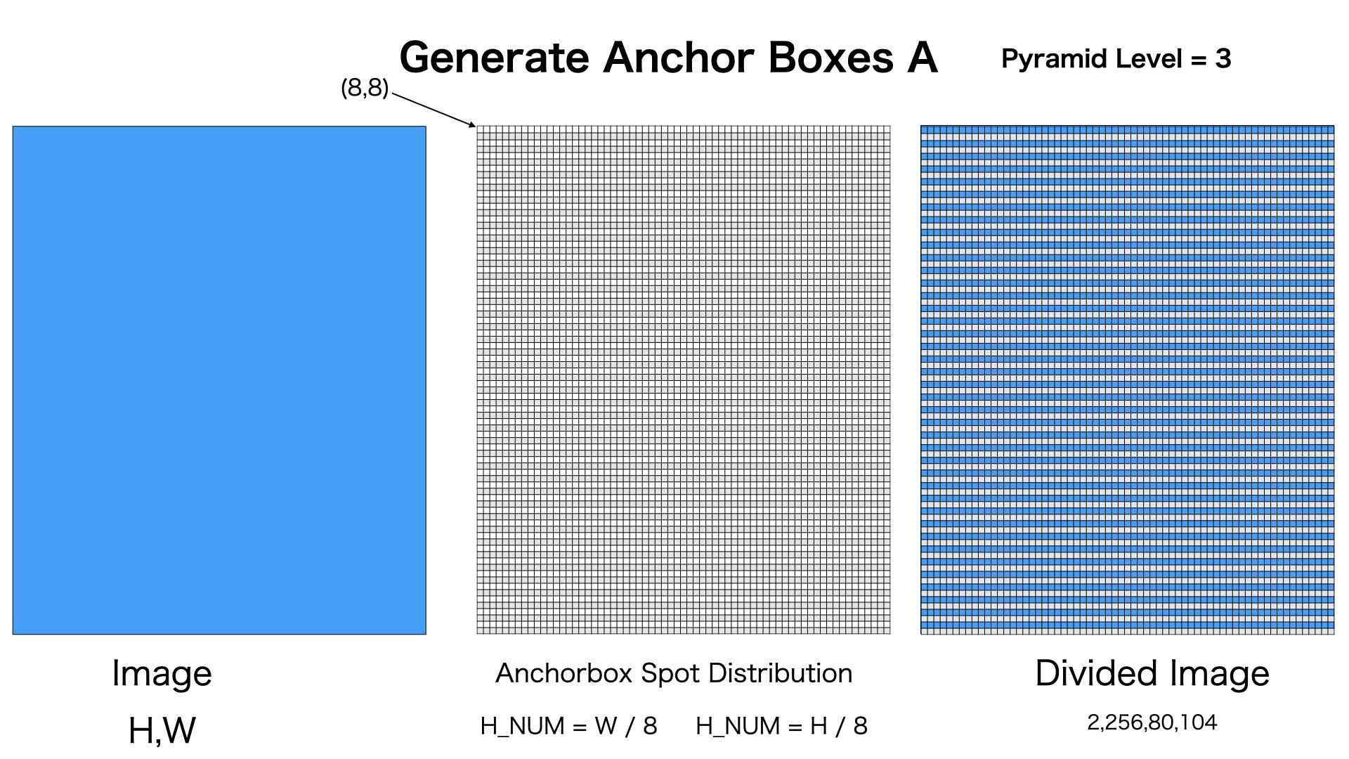
図のように、マスにサイズが8、碁盤のサイズが入力画像のサイズの1/8。
Anchor Boxのサイズは80,104になります
Anchor Box B####
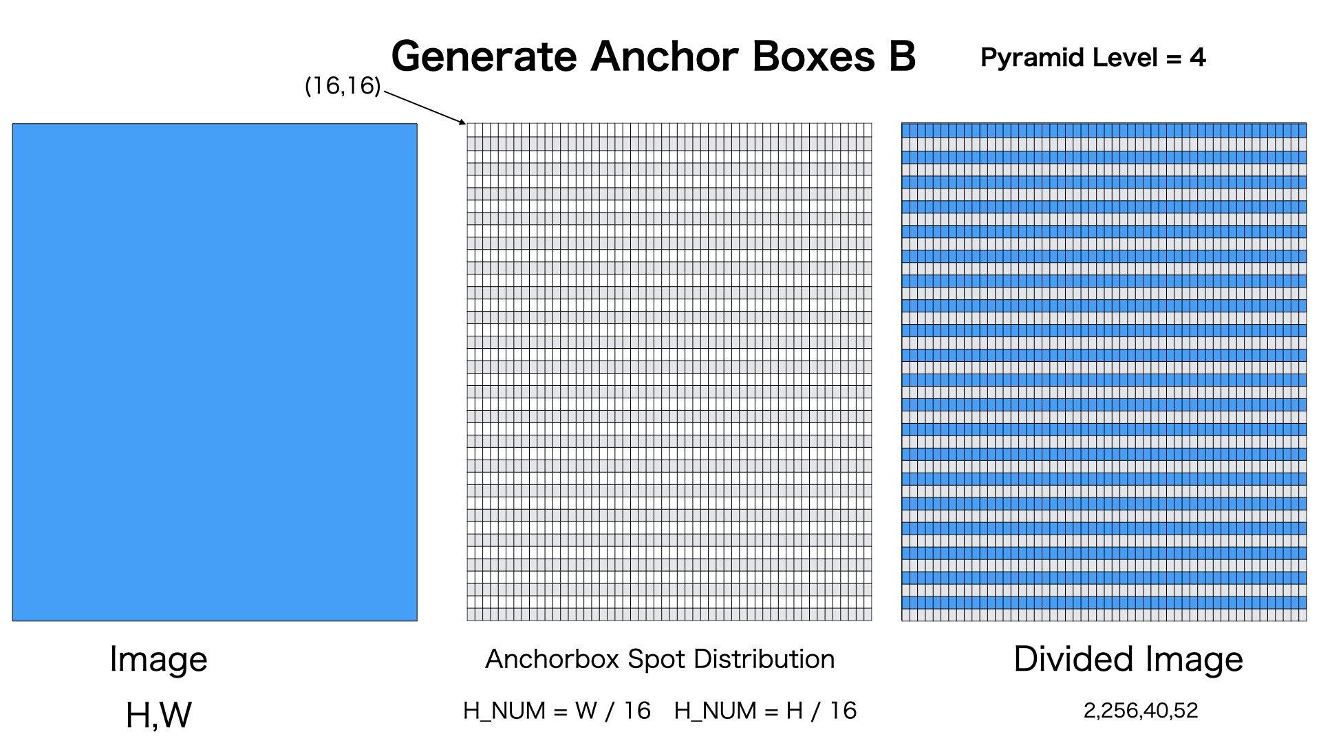
図のように、マスにサイズが16、碁盤のサイズが入力画像のサイズの1/16。
Anchor Boxのサイズは40,52になります
Anchor Box C####
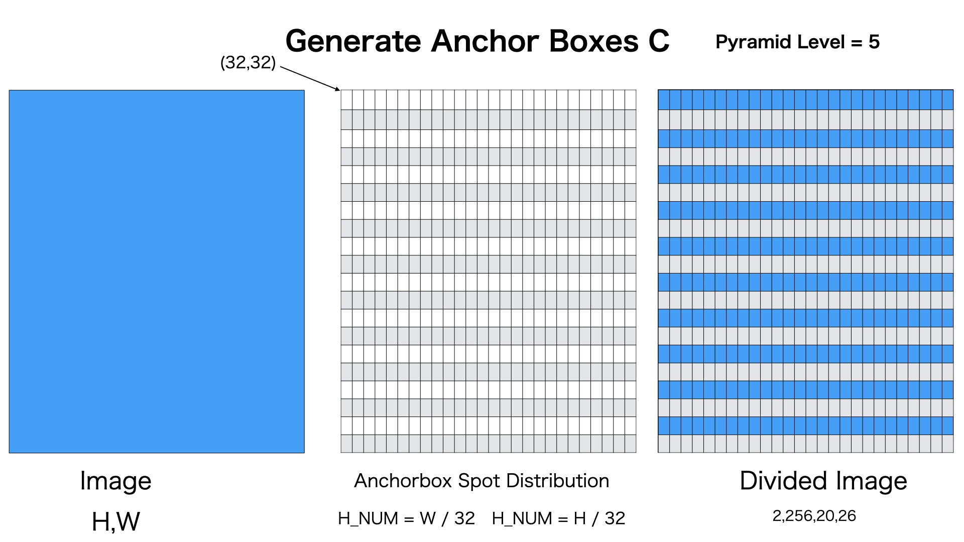
図のように、マスにサイズが32、碁盤のサイズが入力画像のサイズの1/32。
Anchor Boxのサイズは20,26になります
Anchor Box D####
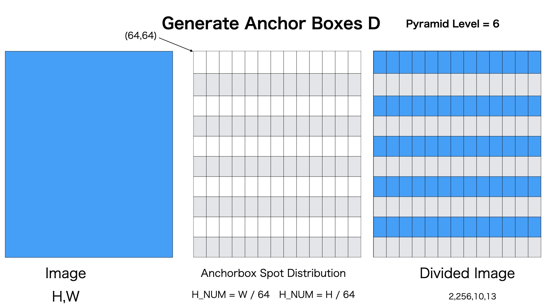
図のように、マスにサイズが64、碁盤のサイズが入力画像のサイズの1/64。
Anchor Boxのサイズは10,13になります
Anchor Box E####
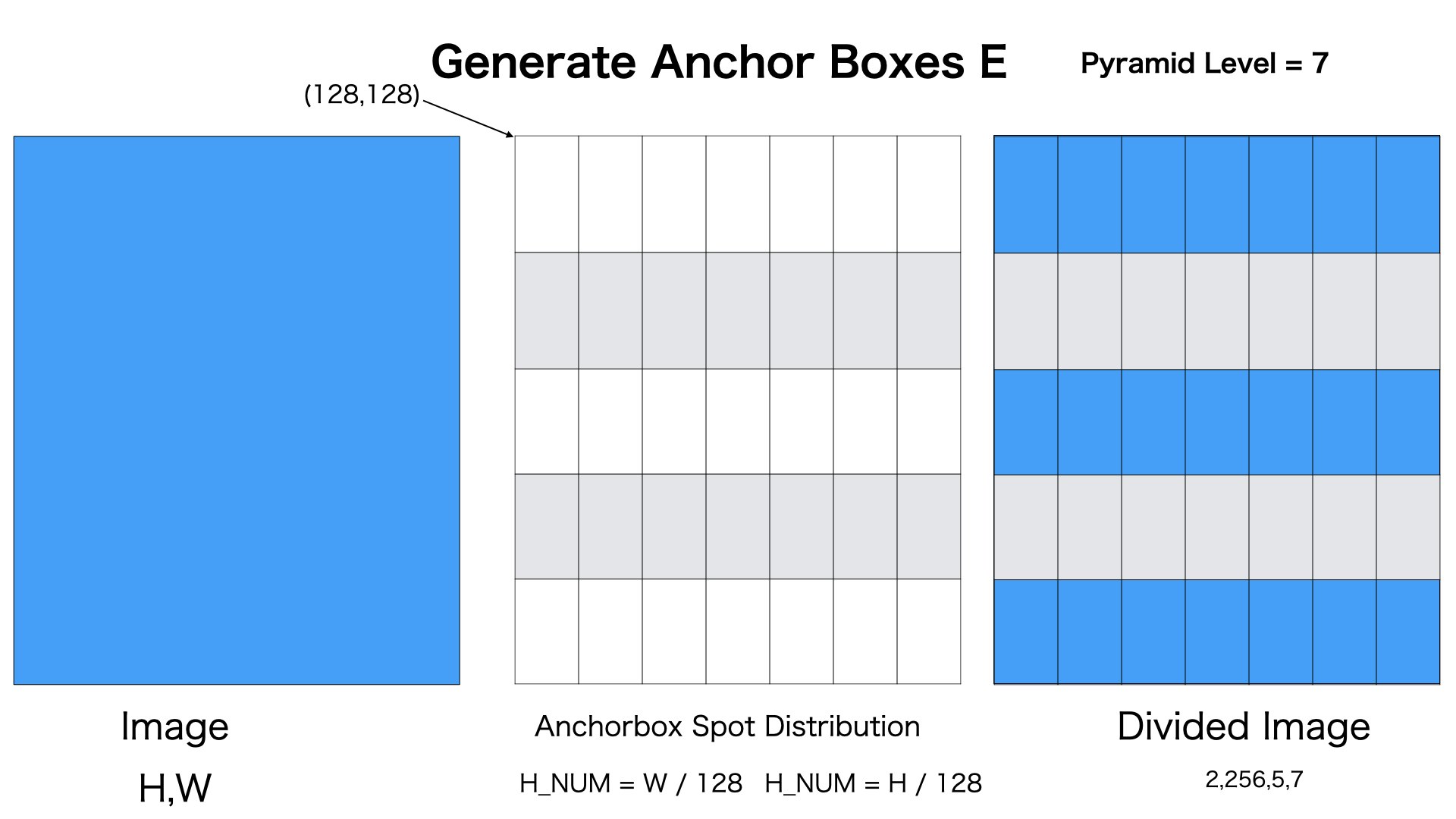
図のように、マスにサイズが128、碁盤のサイズが入力画像のサイズの1/128。
Anchor Boxのサイズは5,7になります
囲碁の碁盤を計算####
図のように、マスのサイズ、マスとマス間の間隔はpyramid levelによって、定められます。
一つ注意点があります。
A,B,C,D,Eのサイズを計算するときに、単純に1/2**(pyramid level)にしたら、
feature pyramid layerの出力に合わせれない場合もあります。
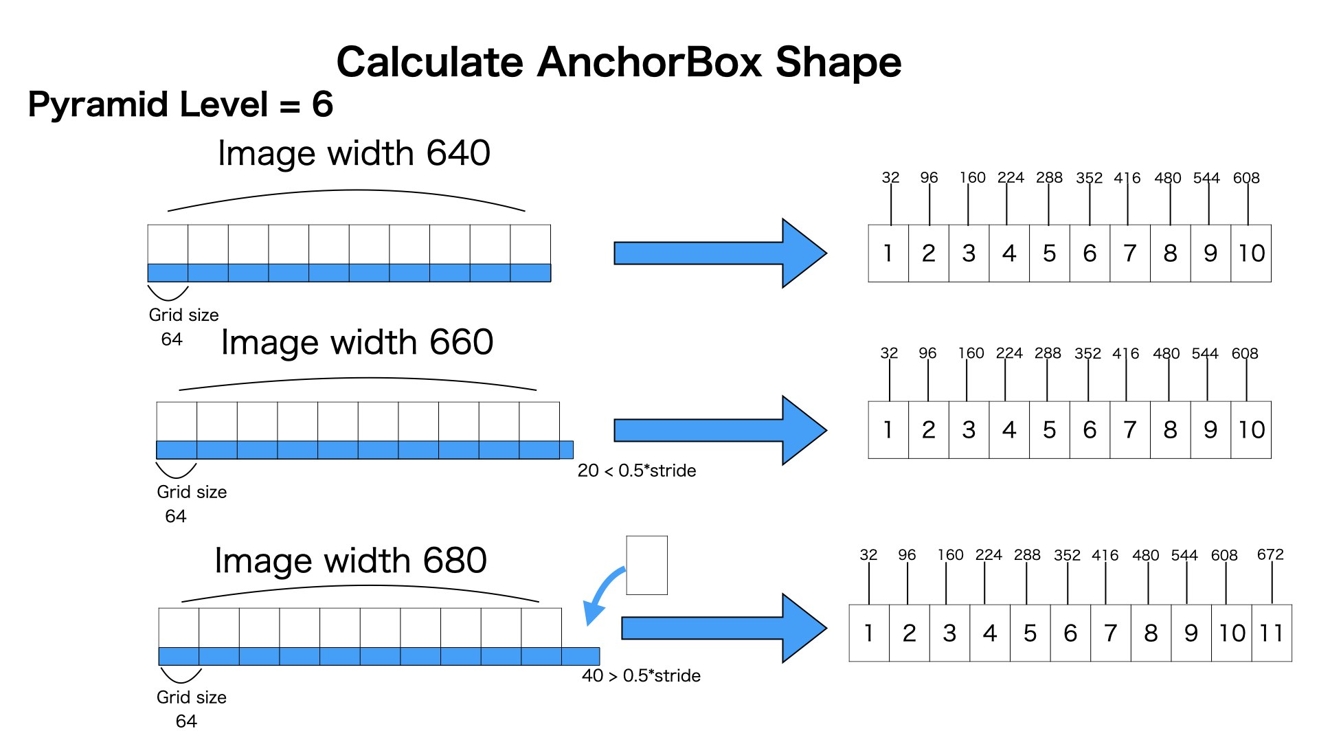
例えば、図のように
pyramid levelが6の場合は
マスのサイズが64X64です
碁盤のサイズが画像サイズ/64になろうとしたところです。
各マスの中心座標は64ごとに増えていきます
一番上の場合は、画像の横幅をちょっど1/64に割り切りました。
碁盤の横幅サイズは10になります。
真ん中の場合は、画像の横幅をちょっど1/64に割り切りませんでした。あまりは20です。20はマスサイズの半分以下であるため、碁盤の横幅サイズを10にします。
したの場合は、、画像の横幅をちょっど1/64に割り切りませんでした。あまりは40です。20はマスサイズの半分以上であるため、この場合はもう一個マスをいれます。碁盤の横幅サイズは11になります。
Anchor Boxのサイズを計算####
各マスを中心にAnchor Boxを生成します。
まずは基本サイズの正方形を生成します。この基本サイズの正方形のサイズがpyramid levelによって定められてます。
そして、この基本サイズの正方形から8個のサイズの正方形と長方形に変形します。
図のように、Anchro Boxの基本サイズはpyramid levelによって、定められます。
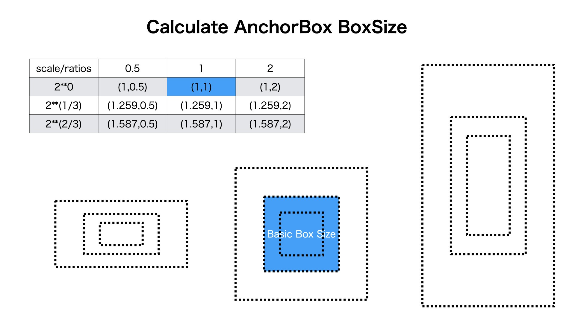
図のように、一つのマスに3つのratioと3つのscaleを与えます。
基本正方形はratioとscaleのすべての組み合わせに沿って、変形します。全部9個のanchor boxが生成されます
ソースコード###
設定###
まずはratio,scale,pyramid levelなどを生成します
import numpy as np
import matplotlib.pyplot as plt

PYRAMID_LEVEL = [3, 4, 5, 6, 7]

TEST_SCALE = np.array([2 ** 0, 2 ** (1.0 / 3.0), 2 ** (2.0 / 3.0)])
TEST_RATIO = np.array([0.5, 1, 2])

strides = [2 ** level for level in PYRAMID_LEVEL]
boxSizeBaseSizes = [2 ** (level + 2) for level in PYRAMID_LEVEL]
imageShape = (640, 832)
原点からanchor boxを生成する####
(0,0)から9個のanchor boxを生成します。
あとからoffsetをかけて、移動させます。
def generate_anchorbox(boxSize, scale, ratios):
    prevBoxsScales = np.tile(scale, (2, len(scale))).T
    prevBoxsScales = prevBoxsScales * boxSize

    preBoxAreas = prevBoxsScales[:, 0] * prevBoxsScales[:, 1]

    # w * h = area
    # w * w*ratio = area
    preBoxRatios = np.repeat(ratios, len(scale))
    preBoxW = np.sqrt(preBoxAreas / preBoxRatios)
    preBoxH = preBoxW * preBoxRatios

    anchorBox = np.zeros((len(scale) * len(ratios), 4))

    anchorBox[:, 2] = preBoxW
    anchorBox[:, 3] = preBoxH

    #
    anchorBox[:, 0::2] -= np.tile(anchorBox[:, 2] * 0.5, (2, 1)).T
    anchorBox[:, 1::2] -= np.tile(anchorBox[:, 3] * 0.5, (2, 1)).T
    return anchorBox
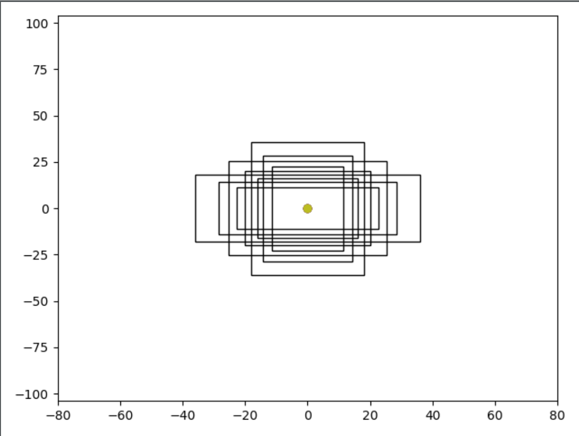
テスト
def run_generate_anchorbox():
    idx = 0
    anchorBoxSizes = generate_anchorbox(boxSizeBaseSizes[idx], TEST_SCALE, TEST_RATIO)


    fig = plt.figure()
    ax = fig.add_subplot(111)

    for box in anchorBoxSizes:
        print(box)
        x1 = box[0]
        y1 = box[1]
        x2 = box[2]
        y2 = box[3]
        cx = 0
        cy = 0
        width = x2 - x1
        height = y2 - y1
        plt.plot(cx, cy, "o")
        rect = plt.Rectangle([x1, y1], width, height, fill=None)
        ax.add_patch(rect)
    plt.xlim(-imageShape[0]/(2**PYRAMID_LEVEL[idx]), imageShape[0]/(2**PYRAMID_LEVEL[idx]))
    plt.ylim(-imageShape[1]/(2**PYRAMID_LEVEL[idx]), imageShape[1]/(2**PYRAMID_LEVEL[idx]))
    plt.show()

run_generate_anchorbox()
pyramid levelを3にして、走ってみたら、結果は以下です
碁盤のマスに移動させます####
def shift_boxes(positionFixedAnchorBoxes, imageShape, stride, boxSizeBaseSize):
    imageWidth = imageShape[1]
    imageHeight = imageShape[0]

    featuresWidth = int((imageWidth + 0.5 * stride) / stride)
    featureHeight = int((imageHeight + 0.5 * stride) / stride)

    featureXCoordinates = np.arange(0, featuresWidth) + 0.5
    featureYCoordinates = np.arange(0, featureHeight) + 0.5

    featureXCoordinates = featureXCoordinates * stride
    featureYCoordinates = featureYCoordinates * stride

    a, b = np.meshgrid(featureXCoordinates, featureYCoordinates)
    m = np.vstack((a.ravel(), b.ravel(), a.ravel(), b.ravel()))
    m = m.transpose()

    positionFixedAnchorBoxes = np.expand_dims(positionFixedAnchorBoxes, 0)
    m = np.expand_dims(m, 1)

    res = m + positionFixedAnchorBoxes

    return m[:, :, :2], res
テスト
def run_shift_boxes():
    idx = 0
    position_fixed_anchor_boxes = generate_anchorbox(boxSizeBaseSizes[idx], TEST_SCALE, TEST_RATIO)
    centerPositions, transformed_anchor_boxes = shift_boxes(position_fixed_anchor_boxes, imageShape, strides[idx],
                                                            boxSizeBaseSizes[idx])

    x = centerPositions[:, :, 0].ravel()
    y = centerPositions[:, :, 1].ravel()
    plt.plot(x, y, "o", markersize=0.3, markerfacecolor='black')
    plt.show()

    fig = plt.figure()
    ax = fig.add_subplot(111)

    totalFeatureBoxNum = centerPositions.shape[0]
    testPoint1 = int(totalFeatureBoxNum*(0.056))
    testPoint2 = int(totalFeatureBoxNum*(0.257))
    testPoint3 = int(totalFeatureBoxNum*(0.395))
    testPoint4 = int(totalFeatureBoxNum*(0.689))
    testPoint5 = int(totalFeatureBoxNum*(0.903))
    sample_anchor_points = [testPoint1,testPoint2,testPoint3,testPoint4,testPoint5]

    for sample_point_index in sample_anchor_points:
        for i in range(9):
            x1 = transformed_anchor_boxes[sample_point_index][i][0]
            y1 = transformed_anchor_boxes[sample_point_index][i][1]
            x2 = transformed_anchor_boxes[sample_point_index][i][2]
            y2 = transformed_anchor_boxes[sample_point_index][i][3]
            center = centerPositions[sample_point_index]
            cx = center.ravel()[0]
            cy = center.ravel()[1]
            width = x2 - x1
            height = y2 - y1

            plt.plot(cx, cy, "o")
            rect = plt.Rectangle([x1, y1], width, height, fill=None)
            ax.add_patch(rect)

    plt.xlim(-300, 900)
    plt.ylim(-300, 900)
    plt.show()


run_shift_boxes()
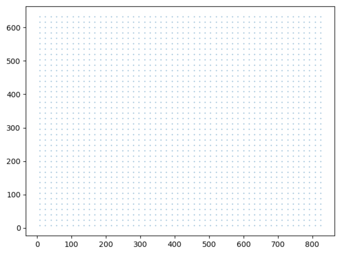
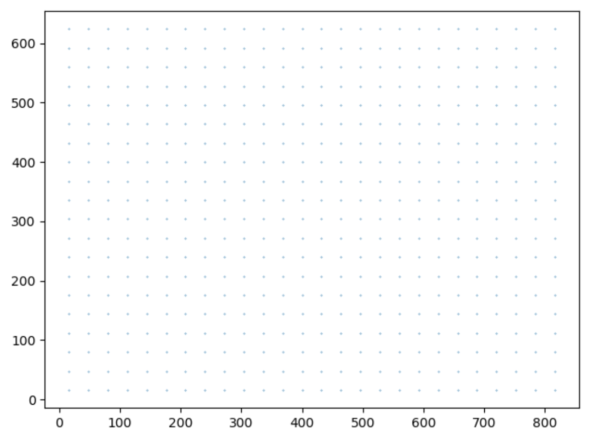
テスト結果A#####
pyramid levelを3にして、走ってみたら、結果は以下です
 図のように生成した囲碁の碁盤(80,104)の中心点を表した図です
 図のように、全体的に5つのところを特定して、生成されたanchor boxを表した図です。
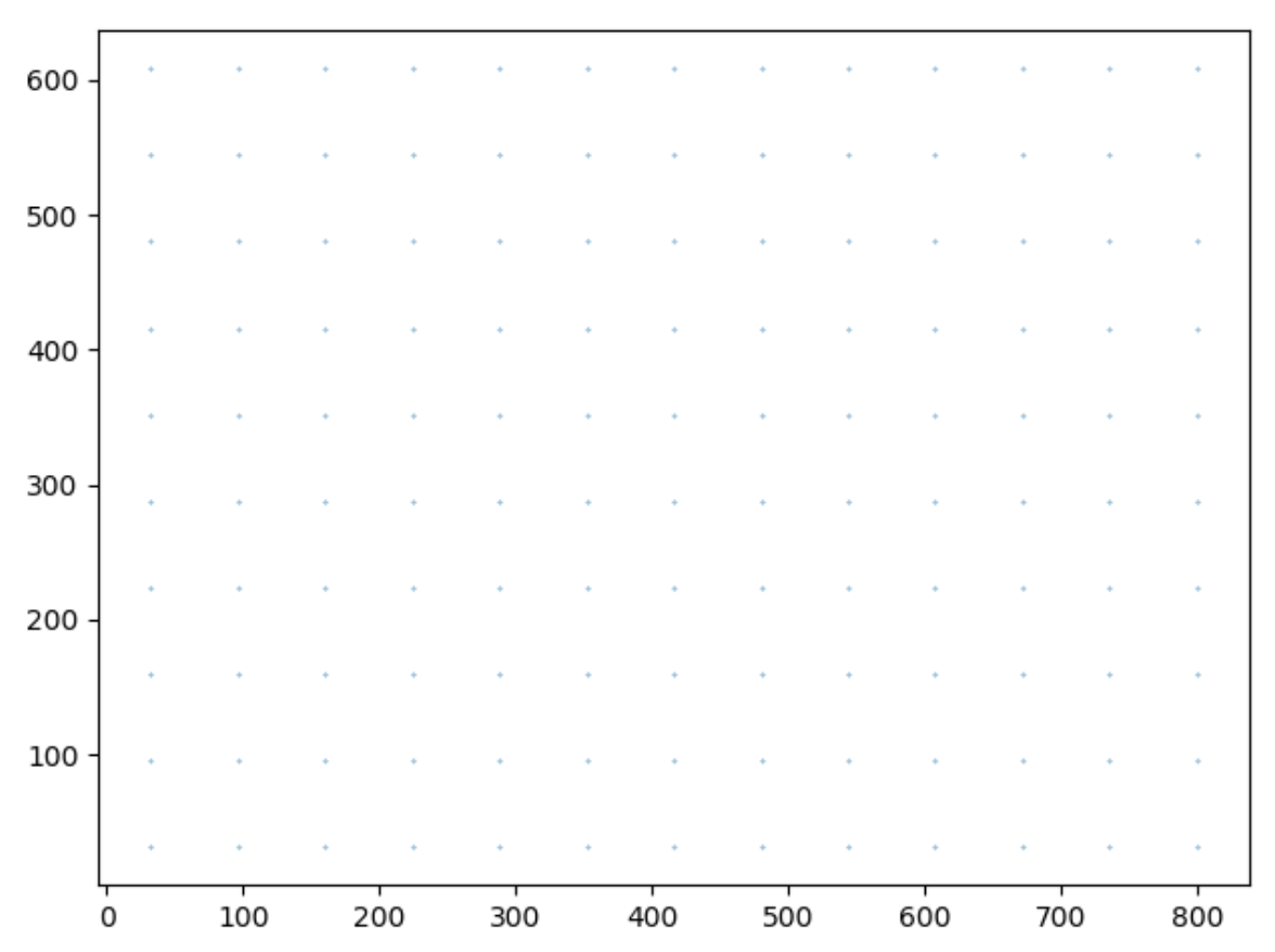
テスト結果B#####
pyramid levelを4にして、走ってみたら、結果は以下です
 図のように生成した囲碁の碁盤(40,52)の中心点を表した図です
点の数がpyramid levelが3の時に生成された点より少なくなりました。
図のように生成した囲碁の碁盤(40,52)の中心点を表した図です
点の数がpyramid levelが3の時に生成された点より少なくなりました。
 図のように、全体的に5つのところを特定して、生成されたanchor boxを表した図です。
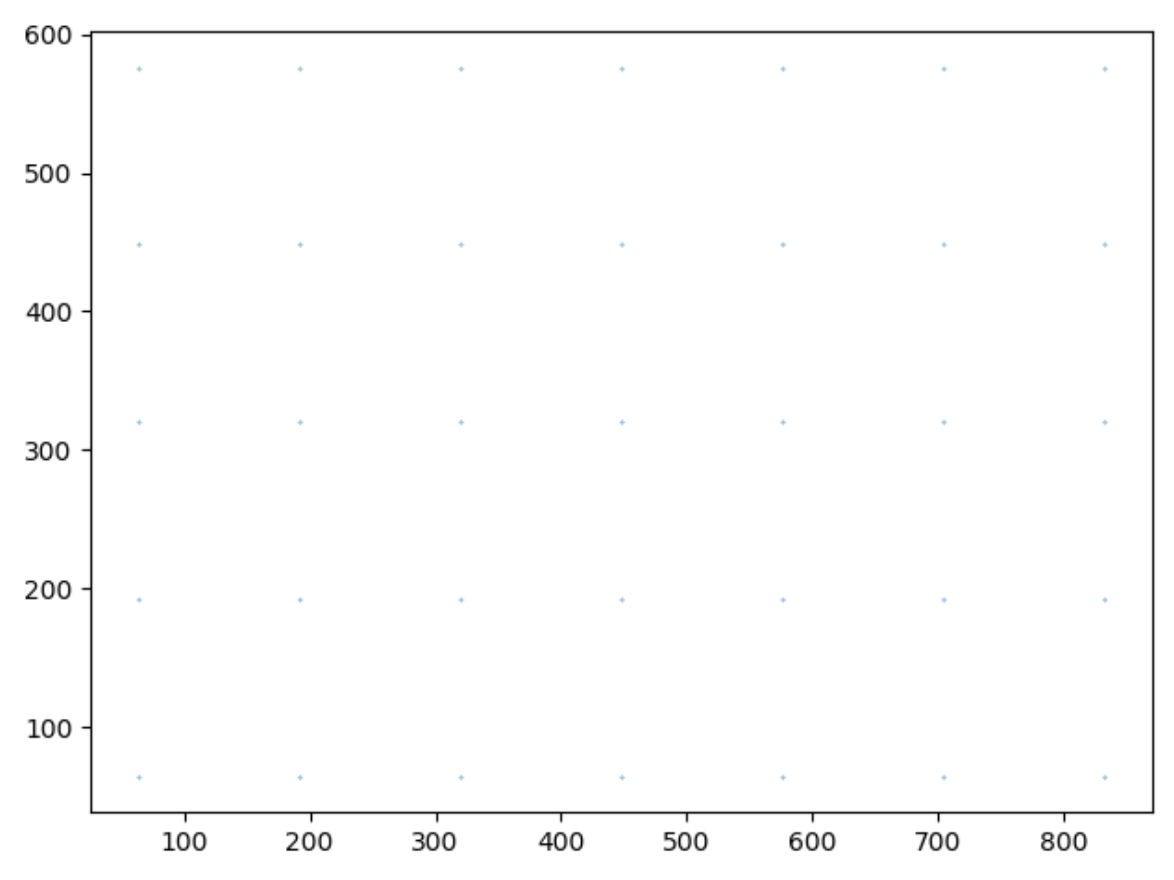
テスト結果C#####
pyramid levelを5にして、走ってみたら、結果は以下です
図のように生成した囲碁の碁盤(20,26)の中心点を表した図です
点の数がpyramid levelが4の時に生成された点より少なくなりました。
 図のように、全体的に5つのところを特定して、生成されたanchor boxを表した図です。
anchor boxのサイズはとても小さいです。それらのanchor boxの目標は小さい物体を検出することです。
図のように、全体的に5つのところを特定して、生成されたanchor boxを表した図です。
anchor boxのサイズはとても小さいです。それらのanchor boxの目標は小さい物体を検出することです。
テスト結果D#####
pyramid levelを6にして、走ってみたら、結果は以下です
図のように生成した囲碁の碁盤(10,13)の中心点を表した図です
点の数がpyramid levelが5の時に生成された点より少なくなりました。
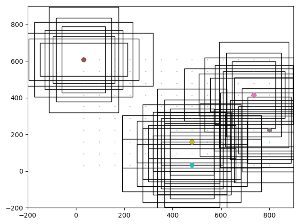 図のように、全体的に5つのところを特定して、生成されたanchor boxを表した図です。
テスト結果E#####
pyramid levelを7にして、走ってみたら、結果は以下です
図のように生成した囲碁の碁盤(5,7)の中心点を表した図です
点の数がpyramid levelが6の時に生成された点より少なくなりました。
 図のように、全体的に5つのところを特定して、生成されたanchor boxを表した図です。
anchor boxのサイズは結構大きいです。それらのanchor boxの目標は大きな物体を検出することです。
図のように、全体的に5つのところを特定して、生成されたanchor boxを表した図です。
anchor boxのサイズは結構大きいです。それらのanchor boxの目標は大きな物体を検出することです。
まとめ###
本節はanchor boxを生成する方法を紹介しました
anchor boxの数はfeature pyramid layersの出力によって、決められてます。
生成されたanchor boxをさらにRegression LayerとClassification Layerの出力を連携して、訓練を実施します。
それは次回紹介したいと思います。