Nordic Nrf528xxを使ってみよう nrf52840 Uno Arduino編(MDBT50Q)の続きです。
https://qiita.com/usashirou/items/a060a116f1f280bf8451
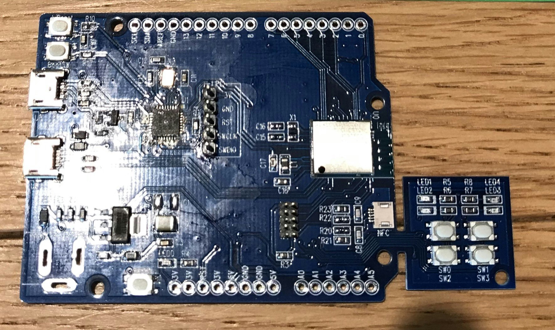
今度はnrf52840 MDBT50Q を搭載したArduino Uno用のボードデータを作成してみましょう。
(nrf52840DKと基本は同じですので、DKボードを持っている方は、以下のプロファイルを作成すると、4ボタン、4LEDを使用可能です)
- boards.txtの記述追加
- ハードウェアファイル追加
を行います。
本記述内容はGithubからダウンロード可能です。
https://github.com/taisirou/nrf52840-Arduino-Uno
boards.txtへの記述追加
C:\ユーザー名\AppData\Local\Arduino15\packages\adafruit\hardware\nrf52\バージョン名\boards.txt
以下を一番下に追加します。
# ----------------------------------
# Arduino Uno nRF52840DK (PCA10056)
# ----------------------------------
uno-nrf52840.name=Arduino Uno nRF52840DK
uno-nrf52840.bootloader.tool=bootburn

# Upload
uno-nrf52840.upload.tool=nrfutil
uno-nrf52840.upload.protocol=nrfutil
uno-nrf52840.upload.use_1200bps_touch=true
uno-nrf52840.upload.wait_for_upload_port=true
uno-nrf52840.upload.maximum_size=815104
uno-nrf52840.upload.maximum_data_size=248832

# Build
uno-nrf52840.build.mcu=cortex-m4
uno-nrf52840.build.f_cpu=64000000
uno-nrf52840.build.board=uno_nrf52840
uno-nrf52840.build.core=nRF5
uno-nrf52840.build.variant=uno_nrf52840
uno-nrf52840.build.usb_manufacturer="Nordic"
uno-nrf52840.build.usb_product="Uno nRF52840"
uno-nrf52840.build.extra_flags=-DNRF52840_XXAA {build.flags.usb}
uno-nrf52840.build.ldscript=nrf52840_s140_v6.ld
uno-nrf52840.build.vid=0x239A
uno-nrf52840.build.pid=0x8029

# SofDevice Menu
uno-nrf52840.menu.softdevice.s140v6=0.2.13 SoftDevice s140 6.1.1
uno-nrf52840.menu.softdevice.s140v6.build.sd_name=s140
uno-nrf52840.menu.softdevice.s140v6.build.sd_version=6.1.1
uno-nrf52840.menu.softdevice.s140v6.build.sd_fwid=0x00B6

# Debug Menu
uno-nrf52840.menu.debug.l0=Level 0 (Release)
uno-nrf52840.menu.debug.l0.build.debug_flags=-DCFG_DEBUG=0
uno-nrf52840.menu.debug.l1=Level 1 (Error Message)
uno-nrf52840.menu.debug.l1.build.debug_flags=-DCFG_DEBUG=1
uno-nrf52840.menu.debug.l2=Level 2 (Full Debug)
uno-nrf52840.menu.debug.l2.build.debug_flags=-DCFG_DEBUG=2
uno-nrf52840.menu.debug.l3=Level 3 (Segger SystemView)
uno-nrf52840.menu.debug.l3.build.debug_flags=-DCFG_DEBUG=3
- ハードウェアファイル
uno-nrf52840.name=Arduino Uno nRF52840DK
uno-nrf52840.build.variant=uno_nrf52840
でハードウェアファイルのあるフォルダを指定してあげます。
ハードウェアファイル追加
以下フォルダに
C:\ユーザー名\AppData\Local\Arduino15\packages\adafruit\hardware\nrf52\バージョン名\variants\uno_nrf52840
以下ファイルを追加します。
- variant.h
- variant.cpp
C:\ユーザー名\AppData\Local\Arduino15\packages\adafruit\hardware\nrf52\バージョン名\variants\uno_nrf52840\variant.h
  /*
  Copyright (c) 2014-2015 Arduino LLC.  All right reserved.
  Copyright (c) 2016 Sandeep Mistry All right reserved.
  Copyright (c) 2018, Adafruit Industries (adafruit.com)

  This library is free software; you can redistribute it and/or
  modify it under the terms of the GNU Lesser General Public
  License as published by the Free Software Foundation; either
  version 2.1 of the License, or (at your option) any later version.
  This library is distributed in the hope that it will be useful,
  but WITHOUT ANY WARRANTY; without even the implied warranty of
  MERCHANTABILITY or FITNESS FOR A PARTICULAR PURPOSE.
  See the GNU Lesser General Public License for more details.
  You should have received a copy of the GNU Lesser General Public
  License along with this library; if not, write to the Free Software
  Foundation, Inc., 51 Franklin St, Fifth Floor, Boston, MA  02110-1301  USA
*/

# ifndef _VARIANT_PCA10056_
# define _VARIANT_PCA10056_

/** Master clock frequency */
# define VARIANT_MCK       (64000000ul)

# define USE_LFXO      // Board uses 32khz crystal for LF
// define USE_LFRC    // Board uses RC for LF

/*----------------------------------------------------------------------------
 *        Headers
 *----------------------------------------------------------------------------*/

# include "WVariant.h"

# ifdef __cplusplus
extern "C"
{
# endif // __cplusplus

// Number of pins defined in PinDescription array
# define PINS_COUNT           (48)
# define NUM_DIGITAL_PINS     (48)
# define NUM_ANALOG_INPUTS    (6)
# define NUM_ANALOG_OUTPUTS   (0)

// LEDs
# define PIN_LED1             (13)
# define PIN_LED2             (14)
# define PIN_LED3             (15)
# define PIN_LED4             (16)

# define LED_BUILTIN          PIN_LED1
# define LED_CONN             PIN_LED2

# define LED_RED              PIN_LED1
# define LED_BLUE             PIN_LED2
# define LED_YELLOW           PIN_LED3
# define LED_GREEN            PIN_LED4

# define LED_STATE_ON         0         // State when LED is litted

// BUTTONs
# define PIN_BUTTON1         (11)
# define PIN_BUTTON2         (12)
# define PIN_BUTTON3         (24)
# define PIN_BUTTON4         (25)

# define SW0              PIN_BUTTON1
# define SW1              PIN_BUTTON2
# define SW2              PIN_BUTTON3
# define SW3              PIN_BUTTON4

/*
 * Analog pins
 */
# define PIN_A0               (3)
# define PIN_A1               (4)
# define PIN_A2               (28)
# define PIN_A3               (29)
# define PIN_A4               (30)
# define PIN_A5               (31)
# define PIN_A6               (0xff)
# define PIN_A7               (0xff)

static const uint8_t A0  = PIN_A0 ;
static const uint8_t A1  = PIN_A1 ;
static const uint8_t A2  = PIN_A2 ;
static const uint8_t A3  = PIN_A3 ;
static const uint8_t A4  = PIN_A4 ;
static const uint8_t A5  = PIN_A5 ;
static const uint8_t A6  = PIN_A6 ;
static const uint8_t A7  = PIN_A7 ;
# define ADC_RESOLUTION    14

// Other pins
# define PIN_AREF           (2)
# define PIN_NFC1           (9)
# define PIN_NFC2           (10)

static const uint8_t AREF = PIN_AREF;

/*
 * Serial interfaces
 */
# define PIN_SERIAL_RX       (8)
# define PIN_SERIAL_TX       (6)
/*
//#define PIN_SERIAL2_RX      (8)
//#define PIN_SERIAL2_TX      (6)

# define PIN_SERIAL_RX       (33)
# define PIN_SERIAL_TX       (34)


/*
 * SPI Interfaces
 */
# define SPI_INTERFACES_COUNT 1

# define PIN_SPI_MISO         (46)
# define PIN_SPI_MOSI         (45)
# define PIN_SPI_SCK          (47)

static const uint8_t SS   = 44 ;
static const uint8_t MOSI = PIN_SPI_MOSI ;
static const uint8_t MISO = PIN_SPI_MISO ;
static const uint8_t SCK  = PIN_SPI_SCK ;

/*
 * Wire Interfaces
 */
# define WIRE_INTERFACES_COUNT 1

# define PIN_WIRE_SDA         (26)
# define PIN_WIRE_SCL         (27)
/*
// QSPI Pins
# define PIN_QSPI_SCK         19
# define PIN_QSPI_CS          17
# define PIN_QSPI_IO0         20
# define PIN_QSPI_IO1         21
# define PIN_QSPI_IO2         22
# define PIN_QSPI_IO3         23

// On-board QSPI Flash
# define EXTERNAL_FLASH_DEVICES   MX25R6435F

# define USB_MSC_BLOCK_SIZE    512
# define USB_MSC_BLOCK_COUNT   ((8*1024*1024) / USB_MSC_BLOCK_SIZE)
*/
# ifdef __cplusplus
}
# endif

/*----------------------------------------------------------------------------
 *        Arduino objects - C++ only
 *----------------------------------------------------------------------------*/

# endif
C:\ユーザー名\AppData\Local\Arduino15\packages\adafruit\hardware\nrf52\バージョン名\variants\uno_nrf52840\variant.cpp
/*
  Copyright (c) 2014-2015 Arduino LLC.  All right reserved.
  Copyright (c) 2016 Sandeep Mistry All right reserved.
  Copyright (c) 2018, Adafruit Industries (adafruit.com)
  This library is free software; you can redistribute it and/or
  modify it under the terms of the GNU Lesser General Public
  License as published by the Free Software Foundation; either
  version 2.1 of the License, or (at your option) any later version.
  This library is distributed in the hope that it will be useful,
  but WITHOUT ANY WARRANTY; without even the implied warranty of
  MERCHANTABILITY or FITNESS FOR A PARTICULAR PURPOSE.
  See the GNU Lesser General Public License for more details.
  You should have received a copy of the GNU Lesser General Public
  License along with this library; if not, write to the Free Software
  Foundation, Inc., 51 Franklin St, Fifth Floor, Boston, MA  02110-1301  USA
*/

# include "variant.h"
# include "wiring_constants.h"
# include "wiring_digital.h"
# include "nrf.h"

const uint32_t g_ADigitalPinMap[] =
{
  // P0
  0 , 1 , 2 , 3 , 4 , 5 , 6 , 7 ,
  8 , 9 , 10, 11, 12, 13, 14, 15,
  16, 17, 18, 19, 20, 21, 22, 23,
  24, 25, 26, 27, 28, 29, 30, 31,

  // P1
  32, 33, 34, 35, 36, 37, 38, 39,
  40, 41, 42, 43, 44, 45, 46, 47
};


void initVariant()
{
  // LED1 & LED2
  pinMode(PIN_LED1, OUTPUT);
  ledOff(PIN_LED1);

  pinMode(PIN_LED2, OUTPUT);
  ledOff(PIN_LED2);;
}
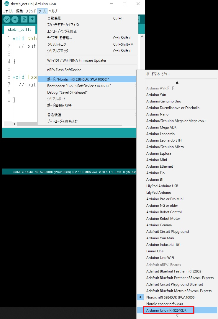
Arduino IDEを再起動すると、ボードマネージャーにArduino Uno nRF52840DKと出れば完成です。
それでは、4つのLEDを点滅させてみます。
4Blink
/*
  Blink

  Turns an LED on for one second, then off for one second, repeatedly.

  Most Arduinos have an on-board LED you can control. On the UNO, MEGA and ZERO
  it is attached to digital pin 13, on MKR1000 on pin 6. LED_BUILTIN is set to
  the correct LED pin independent of which board is used.
  If you want to know what pin the on-board LED is connected to on your Arduino
  model, check the Technical Specs of your board at:
  https://www.arduino.cc/en/Main/Products

  modified 8 May 2014
  by Scott Fitzgerald
  modified 2 Sep 2016
  by Arturo Guadalupi
  modified 8 Sep 2016
  by Colby Newman

  This example code is in the public domain.

  http://www.arduino.cc/en/Tutorial/Blink
*/

// the setup function runs once when you press reset or power the board
void setup() {
  // initialize digital pin LED_BUILTIN as an output.
  pinMode(PIN_LED1, OUTPUT);
  pinMode(PIN_LED2, OUTPUT);
  pinMode(PIN_LED3, OUTPUT);
  pinMode(PIN_LED4, OUTPUT);
}

// the loop function runs over and over again forever
void loop() {
  digitalWrite(PIN_LED1, HIGH);   // turn the LED on (HIGH is the voltage level)
  digitalWrite(PIN_LED2, LOW);   // turn the LED off by making the voltage LOW
  digitalWrite(PIN_LED3, LOW);   // turn the LED off by making the voltage LOW
  digitalWrite(PIN_LED4, LOW);   // turn the LED off by making the voltage LOW
  delay(1000);                       // wait for a second
  digitalWrite(PIN_LED1, HIGH);   // turn the LED on (HIGH is the voltage level)
  digitalWrite(PIN_LED2, HIGH);   // turn the LED on (HIGH is the voltage level)
  digitalWrite(PIN_LED3, LOW);   // turn the LED off by making the voltage LOW
  digitalWrite(PIN_LED4, LOW);   // turn the LED off by making the voltage LOW
  delay(1000);
  digitalWrite(PIN_LED1, HIGH);   // turn the LED on (HIGH is the voltage level)
  digitalWrite(PIN_LED2, HIGH);   // turn the LED on (HIGH is the voltage level)
  digitalWrite(PIN_LED3, HIGH);   // turn the LED on (HIGH is the voltage level)
  digitalWrite(PIN_LED4, HIGH);   // turn the LED on (HIGH is the voltage level)
  delay(1000);
  digitalWrite(PIN_LED1, LOW);    // turn the LED off by making the voltage LOW
  digitalWrite(PIN_LED2, LOW);   // turn the LED off by making the voltage LOW
  digitalWrite(PIN_LED3, LOW);   // turn the LED off by making the voltage LOW
  digitalWrite(PIN_LED4, LOW);   // turn the LED off by making the voltage LOW
  delay(1000);                       // wait for a second
}
Button to LED
ボタンを押したらLEDが点くプログラム
/*
  Button

  Turns on and off a light emitting diode(LED) connected to digital pin 13,
  when pressing a pushbutton attached to pin 2.

  The circuit:
  - LED attached from pin 13 to ground
  - pushbutton attached to pin 2 from +5V
  - 10K resistor attached to pin 2 from ground

  - Note: on most Arduinos there is already an LED on the board
    attached to pin 13.

  created 2005
  by DojoDave <http://www.0j0.org>
  modified 30 Aug 2011
  by Tom Igoe

  This example code is in the public domain.

  http://www.arduino.cc/en/Tutorial/Button
*/

// variables will change:
int buttonState = 0;         // variable for reading the pushbutton status

void setup() {
  pinMode(PIN_LED1, OUTPUT);
  pinMode(PIN_LED2, OUTPUT);
  pinMode(PIN_LED3, OUTPUT);
  pinMode(PIN_LED4, OUTPUT);
  // initialize the pushbutton pin as an input:
  pinMode(PIN_BUTTON1, INPUT);
  pinMode(PIN_BUTTON2, INPUT);
  pinMode(PIN_BUTTON3, INPUT);
  pinMode(PIN_BUTTON4, INPUT);
}

void loop() {
  // read the state of the pushbutton value:
  buttonState = digitalRead(PIN_BUTTON1);
  // check if the pushbutton is pressed. If it is, the buttonState is HIGH:
  if (buttonState == HIGH) {
    // turn LED on:
    digitalWrite(PIN_LED1,HIGH );
  } else {
    // turn LED off:
    digitalWrite(PIN_LED1, LOW);
  }
   buttonState = digitalRead(PIN_BUTTON2);
  // check if the pushbutton is pressed. If it is, the buttonState is HIGH:
  if (buttonState == HIGH) {
    // turn LED on:
    digitalWrite(PIN_LED2, HIGH);
  } else {
    // turn LED off:
    digitalWrite(PIN_LED2, LOW);
  }
 buttonState = digitalRead(PIN_BUTTON3);
  // check if the pushbutton is pressed. If it is, the buttonState is HIGH:
  if (buttonState == HIGH) {
    // turn LED on:
    digitalWrite(PIN_LED3, HIGH);
  } else {
    // turn LED off:
    digitalWrite(PIN_LED3, LOW);
  }
 buttonState = digitalRead(PIN_BUTTON4);
  // check if the pushbutton is pressed. If it is, the buttonState is HIGH:
  if (buttonState == HIGH) {
    // turn LED on:
    digitalWrite(PIN_LED4, HIGH);
  } else {
    // turn LED off:
    digitalWrite(PIN_LED4, LOW);
  }
}
以上で完成です。