目次
[1]概要
[2]回路図、配線図
[3]時刻設定方法の検討
[4]表示モードの選択
[5]シリアルモニタからのコマンドの仕様
[6]ライブラリのインストール
[7]スケッチ(プログラム)はどうするの?
[8]ライブラリで定義されているメソッドの使い方
[9]使用可能な色と、色の名前
[10]その他、特記事項
[11]スケッチ(プログラム)
[12]関連記事
[1]概要
前回投稿した記事 「ESP32で1.6インチのカラーLCD(130×130ピクセル、SSD1283A)に表示する」 (リンクは最後の関連記事の項参照)ではLCDにASCIIコード表を表示しました。
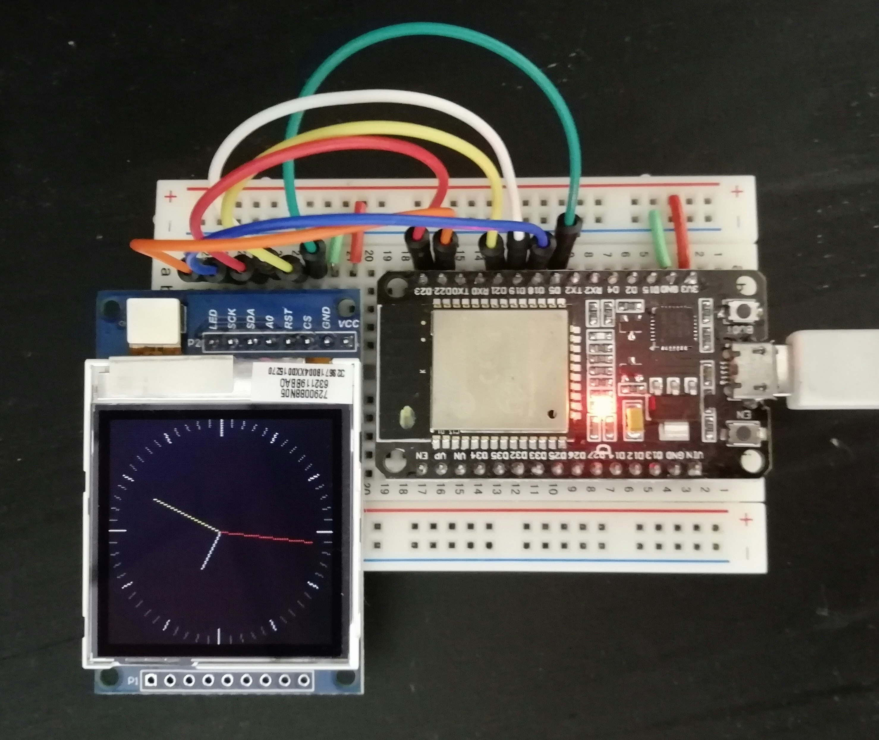
これに続くESP32 + 1.6インチLCDのアプリ第2弾は「時計」です。
GFX Library for Arduino のサンプルスケッチ「Clock」をベースに機能を追加しました。
先ずはオリジナルのアナログ時計は、こんな感じ。
次に、アナログ時計の右下に小さくデジタル表示を加えた「アナ・デジ時計」と「デジタル時計」と「ラーメンタイマー」です。
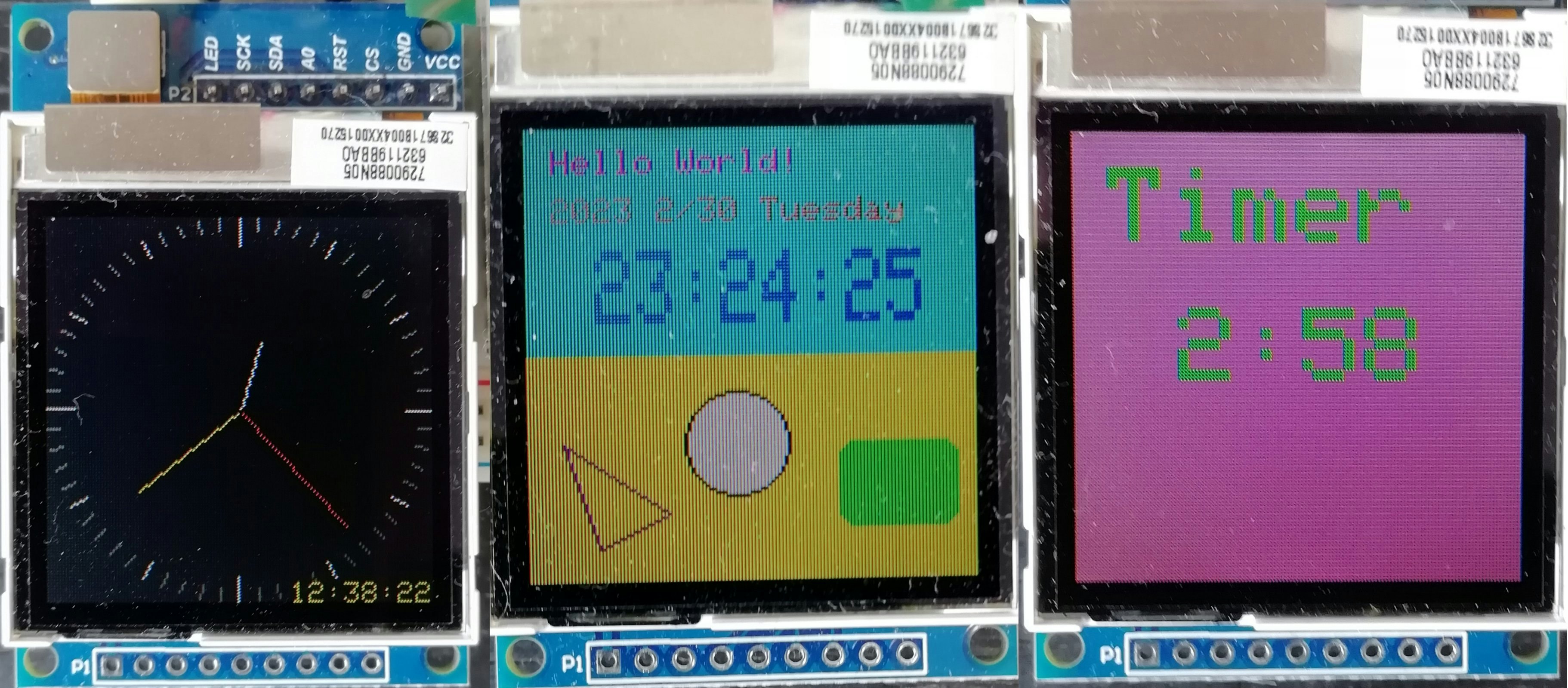
デジタル時計の背景色は今話題の国の国旗を参考にしました。文字だけだと寂しいので丸とか三角の図形を挿入してみました。グラフィック・メソッドの使い方の練習という意味もあります。日付が2月30日ですがバグではなく人を驚かせるための仕様です! というのは嘘で日付・時刻の設定時に月日の関係、妥当性の簡易チェックはしてますが厳密にするのは面倒なので手を抜きました。
ラーメンタイマーというネーミングは微妙な感じでしょうか、キッチンタイマとも言いますが要はダウンカウントします。
これら3種類の時計とタイマーは選択して表示できます。
時計の時刻とタイマーの時間はシリアルモニタで設定します。
※ アナ・デジ時計のアナログとデジタルの時間が一致してない? という突っ込みが入りそうですが、秒針をよ~く見て下さい。ぱっと見23秒ですがまだ22秒です。秒針は1秒毎ではなくもっと細かく動きます。
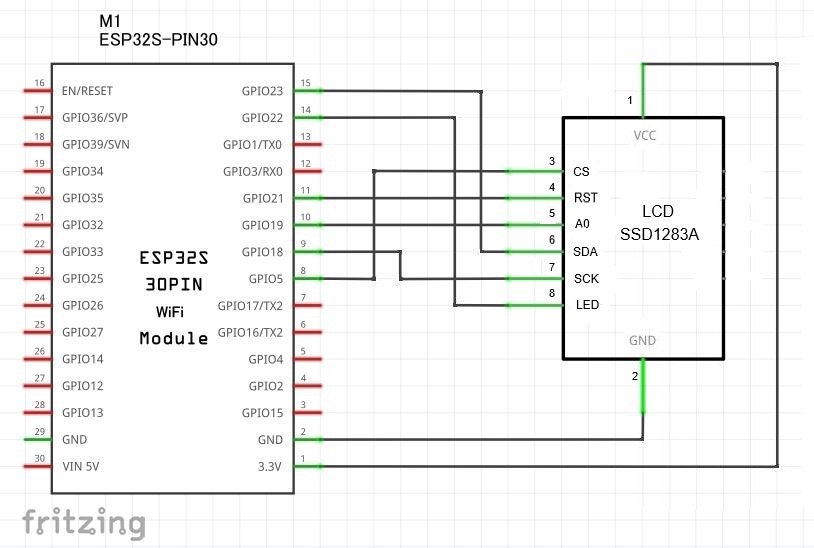
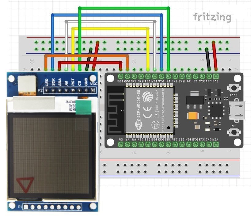
[2]回路図、配線図
前回の投稿記事と同じなので説明は省略します。
[3]時刻設定方法の検討
① インターネットのNTPサーバーで時刻合わせ
② RTC(リアルタイムクロック)
③ GPSを受信して時刻情報を得る
④ 手動設定(設定ボタンで入力する)
⑤ 手動設定(シリアルモニタから入力)
何れの方法も技術的には興味があり、全て試してみたいのですが ①はネット接続が必要、②③④はハードウェア追加が必要です。取り敢えず追加ハード不要で手っ取り早く完成しそうな⑤でいくことにしました。
[4]表示モードの選択
LCDの表示形態は3種類の時計とタイマーの計4つあり、シリアルモニタから選択します。
・アナログ時計
・アナ・デジ時計
・デジタル時計
・ラーメンタイマー(キッチンタイマ)
また、
・時計の時刻
・タイマーの時間
もシリアルモニタから設定します。
[5]シリアルモニタからのコマンドの仕様
コマンドは下記の5つです。
・[A] アナログ時計を表示
・[B] アナ・デジ時計を表示
・[D] デジタル時計を表示
・[R] ラーメンタイマー(キッチンタイマ)表示と時間設定
・[T] 時計の時刻
[A] [B] [D] は1文字だけです。小文字の[a] [b] [d]もOK。
[R] は小文字の[r]もOKでパラメータとして秒数を付加します。
例:r と、パラメータを省略するとデフォルトの 180秒=3分
例:R300 は、300秒=5分
例:r3600 は、3600秒=60分=1時間
[T] は小文字の[t]もOK。パラメータとして年月日・曜日・時分秒を付加します。
例: t2023-0124-2-230900 は、2023 1/24 Tuesday 23:9:0 と表示されます。
曜日は、0=Sunday 1=Monday 2=Tuesday 3=Wednesday 4=Thursday 5=Friday 6=Saturday
注:パラメータは省略できない。また必ず4桁 4桁 2桁 6桁 の数字であること。
数字と数字の間の区切り符号はチェックしてないので空白でも/-,.など何でも可。
パラメータは日付・時刻としての妥当性(数値の範囲)をチェックする。
[A,a] [B,b] [D,d] [R,r] [T,t] 以外のコマンド文字はエラーとする。
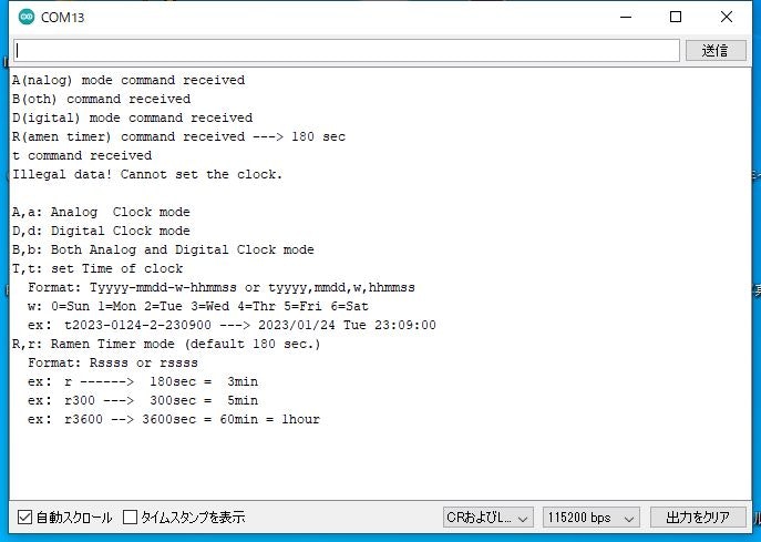
入力エラーの場合、コマンド一覧を表示する。
下図はコマンド入力に対する応答の例です。
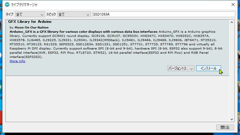
[6]ライブラリのインストール
このSSD1283A搭載のLCDを使用するために必要なライブラリは前回の投稿記事と同じですが、念のため私がインストールした方法を書きます。
Arduino IDE の「ツール」⇒「ライブラリを管理」⇒「ライブラリマネージャ」の検索窓で「SSD1283A」と入力し「GFX Library for Arduino」が表示されたら「インストール」ボタンをクリックします。
[7]スケッチ(プログラム)はどうするの?
GFX Library for Arduino のサンプルスケッチ「Clock」をベースに機能を1つずつ追加していきます。
[注! カスタマイズする前に]
オリジナルには手を付けずに残す。コピーして別名にしたものを編集しましょう。色々コードを改変(改悪?)したけど思ったようにいかず「全て最初からやり直し!」という場面で、いじり過ぎて元のまっさらな状態に戻れなくなる恐れがあるからです。(私はうっかりオリジナルを改変してしまった経験あり)
■ 先ずは手を加えずオリジナルのまま動かしてみたい。ところがスケッチ例は、そのままでは動作しません。使用するボードに合わせてカスタマイズする必要があります。詳細は前回投稿記事(リンクは最後の関連記事の項参照)をご覧下さい。
[8]ライブラリで定義されているメソッドの使い方
Arduino_GFX.h で図形描画やテキスト表示の様々なメソッドが定義されてます。このファイルは私の環境(Windows10)では、C:\Users\user\Documents\Arduino\libraries\GFX_Library_for_Arduino\src
の中にありました。
これらのメソッドの機能や使用方法ですが、このライブラリはAdafruitのものがベースになっているようで、下記サイトもAdafruitがベースですが説明が役に立つというか、ほぼそのまま流用できそうです。
■ Adafruit_GFXでの描画方法(説明は日本語です)
■ Adafruit_GFXクラスのメソッド一覧(説明は日本語です)
[9]使用可能な色と、色の名前
例えば、
gfx->fillScreen(YELLOW); // 画面クリア(画面全体を黄色で塗りつぶす)
といった場合に使用できる色の名前は Arduino_GFX.h で下記のように19の色が定義されてます。
// Color definitions
#define BLACK 0x0000       ///<   0,   0,   0
#define NAVY 0x000F        ///<   0,   0, 123
#define DARKGREEN 0x03E0   ///<   0, 125,   0
#define DARKCYAN 0x03EF    ///<   0, 125, 123
#define MAROON 0x7800      ///< 123,   0,   0
#define PURPLE 0x780F      ///< 123,   0, 123
#define OLIVE 0x7BE0       ///< 123, 125,   0
#define LIGHTGREY 0xC618   ///< 198, 195, 198
#define DARKGREY 0x7BEF    ///< 123, 125, 123
#define BLUE 0x001F        ///<   0,   0, 255
#define GREEN 0x07E0       ///<   0, 255,   0
#define CYAN 0x07FF        ///<   0, 255, 255
#define RED 0xF800         ///< 255,   0,   0
#define MAGENTA 0xF81F     ///< 255,   0, 255
#define YELLOW 0xFFE0      ///< 255, 255,   0
#define WHITE 0xFFFF       ///< 255, 255, 255
#define ORANGE 0xFD20      ///< 255, 165,   0
#define GREENYELLOW 0xAFE5 ///< 173, 255,  41
#define PINK 0xFC18        ///< 255, 130, 198
これらは実際にはどんな色か? これ以外の色を使用するにはどうするの? と疑問に思ったので少し調べて自分なりに理解したことを以下にまとめました。(正確ではないとか間違いがある場合、ご指摘いたければ有難いです)
パソコン等のブラウザで、というかHTMLでは色の指定に24bitのカラーコード(RGBコード)を使用します。Red, Green, Blue のそれぞれを 8bit(256諧調)で指定するので8+8+8=24bit(2の24乗)、256×256×256=16,777,216 種類の色を表現できます。
HTMLでは色の名前として「HTML標準16色」や140個の色名が定義されてます。「カラーコード」で検索すると色の名前、実際の色を一覧できる便利なサイトがいくつかあります。
SSD1283A搭載のLCDでサポートする色は16bitカラーコードと呼ばれるものです。16bitの内訳は R:5bit, G:6bit, B:5bit で 32×64×32=65,536 通りの色を表現します。
16bitカラーコードは「RGB565」、24bitのカラーコードは「RGB888」ともいいます。
■ 24bitから16bitカラーコードへの変換は以下のようにします。
R:8bit の上位5bit ⇒ R:5bit
G:8bit の上位6bit ⇒ G:5bit
B:8bit の上位5bit ⇒ B:5bit
例:Color Name : GhostWhite
#RRGGBB : #F8F8FF (24bit) ⇒ 0xffdf (16bit)
| Color Name | GhostWhite |
|---|---|
| #RRGGBB | #F8F8FF |
| #RRGGBB | 1111 1000 1111 1000 1111 1111 |
| R: 上位5bit | 1111 1 |
| G: 上位6bit | 1111 10 |
| B: 上位5bit | 1111 1 |
| RGB565 | 1111 1 + 1111 10 + 1111 1 |
| RGB565 | 1111 1111 1101 1111 |
| RGB565 | 0xFFDF |
■ 逆に16bitから24bitカラーコードへの変換は以下のようにします。
R:5bit に下位3bit:000 を付加 ⇒ R:8bit
G:6bit に下位2bit:00 を付加 ⇒ G:8bit
B:5bit に下位3bit:000 を付加 ⇒ B:8bit
例:0xffdf (16bit) ⇒ 0x?????? (24bit)
| RGB565 | 0xFFDF |
|---|---|
| RGB565 | 1111 1111 1101 1111 |
| 5,6,5 | 1111 1 + 111 110 + 1 1111 |
| 000,00,000 を付加 | 11111000 + 11111000 + 11111000 |
| RGB888 | 1111 1000 1111 1000 1111 1000 |
| RGB888 | 0xF8F8F8 |
あれっ? #F8F8FF ではないぞ??
この理由ですが、24bitから16bitカラーコードに変換する際、上位5bitまたは6bitのみ取り出して残りの下位bitの情報を捨てました。情報が失われた16bitカラーコードからは元の24bitの情報を復元できません。この変換は不可逆ということですね。(こーゆーの情報落ちって言ったかな?違う? ん10年前の情報処理試験の勉強以来で記憶あいまい)
「16bitカラーコード」の色を確認できるサイトが2つありました。
このサイトで24bitの値を入力すると、その色を表示し、変換ボタンをクリックすると16bitの値と、その色が表示されます。0xF8F8FF と入力して変換ボタンをクリックすると RGB565: 0xffdf と表示され、私の手計算の結果と一致しました。ところが・・・
こちらのサイト、右側の一覧表の上から3つ目を見ると、
GhostWhite #RRGGBB : #F8F8FF ⇒ 16-bit : 0xf7bf
と上記と異なる値です?????
上記サイトからの引用ですが、R,G,Bの3つとも5bitではなくGreenのみbit数が多いのは、コンピュータにとって区切りのいい16bitに調整することと、人間の目は緑色の変化に敏感なためとのことです。
先に挙げたArduino_GFX.h で定義されている19色以外の色を使用したい場合は以下のようにします。
① HTMLのカラーコードのサイト(沢山あります)で望む色の24bitカラーコードを確認します。
② 24bitカラーコードを http://aok.blue.coocan.jp/html5/jscript/rgb565.html で16bitに変換する。
③ 下記のようにコードを書く
 変更前: gfx->fillScreen(YELLOW);  // 画面クリア(画面全体を黄色で塗りつぶす)
 変更後: gfx->fillScreen(0xffdf);  // 画面クリア(画面全体をGhostWhite色で塗りつぶす)
[10]その他、特記事項
以下は特別なことではなく私が知らなかっただけで「んなこたぁ千年前から知ってたぜ」という方も多いかと思いますが私的メモということで・・
■ Arduino には String という文字列クラス があります。なかなか便利です。以下のようなことができますが詳しくは「Arduino String クラス」で検索してください。
Stringの宣言、文字列の連結、String同士の連結、Stringと文字リテラルの連結、
文字列⇔数値の変換(・Stringからint/float ・int⇒String ・float⇒String)、
文字列の切り出し、
任意のインデックス以降の文字列を取得、
任意のインデックス間の文字列を取得、
文字の置換、先頭・末尾のスペース削除、文字列の文字数を取得、
文字配列(char[])に変換、文字の検索
■ オリジナル版の時刻設定はコンパイルした時の時刻です。
    hh = conv2d(__TIME__);
    mm = conv2d(__TIME__ + 3);
    ss = conv2d(__TIME__ + 6);
TIMEの前後を__で囲んだ文字列は、コンパイル時点の時刻を表す文字列(時:分:秒)に置き換わるマクロ定数です。へ~、知らなかった。 時刻があるなら日付もあるだろう・・ということで以下のようにしてデジタル時計に日付も表示することにしました。
    String date;
    String work;
    char month[10];

    date = __DATE__ ;                // ex) "Jan 1 2023", "Jan 31 2023"
    date.toCharArray(month, 4);

    work = date.substring(4,6);   dd = work.toInt();  // day
    work = date.substring(6,11);  yy = work.toInt();  // year
■ Arduino で char を int に変換するには3つの方法があります。
シリアルモニタから受信したタイマの時間(char型)をint に変換する際に、上記の3つ目の方法 Serial.parseInt() を使用しました。
if (Serial.available() > 0) {     // シリアル受信あり
    r_timer = Serial.parseInt();  // char を int に変換する
}
データ受信と変換が1行で出来る! う~ん、便利ですね。
[11]スケッチ(プログラム)------ 699行
ちょっと長くなってしまったかなぁ? 未熟さゆえの冗長なところがあると思います。
■ オリジナルの製作者は moononournation と名乗る香港の方のようです。(moon on our nation 私たちの国の月?)
作者名や版権表示が無くフリーだと思いますが、そのままにしておきます。
商用、非商用を問わず勝手にお使い下さい。但し、物的損害、人的損害、その他色々不具合とか何が起きようとも一切責任は取りません、それで良ければ、ということで。
■ 既知の問題点
(1) 日付・時刻の設定時に月と日と曜日の関係とか、うるう年のチェックなど処理がいい加減なところがあります。例えば2月30日とか、実際と異なる曜日も設定できて表示したりします。手抜きです。
(2) 質問:時刻設定で、必ず4桁 4桁 2桁 6桁 の数字であること、つまりゼロサプレス不可といいながらLCDにはゼロサプレスで表示される、このアンバランス、いい加減さは? こんなことでいいのか!
回答:現状維持とします。今後の対応予定はございません。
/*
GFX Library for Arduino --- Clock
Arduino Watch Lite Version
You may find full version at: https://github.com/moononournation/ArduinoWatch
オリジナルからの変更点
・ESP32 + 1.6インチLCD(SSD1283A)
・アナログ時計に加え、デジタル時計も選択して表示する機能を追加
・アナログ表示と同時にデジタル表示もする機能を追加
・シリアルモニタから日付と時刻を設定する機能を追加
・ラーメンタイマ(キッチンタイマ)機能を追加
2022年10月14日
*/
/*******************************************************************************
* Start of Arduino_GFX setting
*
* Arduino_GFX try to find the settings depends on selected board in Arduino IDE
* Or you can define the display dev kit not in the board list
* Defalult pin list for non display dev kit:
* Arduino Nano, Micro and more: CS: 9, DC: 8, RST: 7, BL: 6, SCK: 13, MOSI: 11, MISO: 12
* ESP32 various dev board : CS: 5, DC: 27, RST: 33, BL: 22, SCK: 18, MOSI: 23, MISO: nil
* ESP32-C3 various dev board : CS: 7, DC: 2, RST: 1, BL: 3, SCK: 4, MOSI: 6, MISO: nil
* ESP32-S2 various dev board : CS: 34, DC: 35, RST: 33, BL: 21, SCK: 36, MOSI: 35, MISO: nil
* ESP32-S3 various dev board : CS: 40, DC: 41, RST: 42, BL: 48, SCK: 36, MOSI: 35, MISO: nil
* ESP8266 various dev board : CS: 15, DC: 4, RST: 2, BL: 5, SCK: 14, MOSI: 13, MISO: 12
* Raspberry Pi Pico dev board : CS: 17, DC: 27, RST: 26, BL: 28, SCK: 18, MOSI: 19, MISO: 16
* RTL8720 BW16 old patch core : CS: 18, DC: 17, RST: 2, BL: 23, SCK: 19, MOSI: 21, MISO: 20
* RTL8720_BW16 Official core : CS: 9, DC: 8, RST: 6, BL: 3, SCK: 10, MOSI: 12, MISO: 11
* RTL8722 dev board : CS: 18, DC: 17, RST: 22, BL: 23, SCK: 13, MOSI: 11, MISO: 12
* RTL8722_mini dev board : CS: 12, DC: 14, RST: 15, BL: 13, SCK: 11, MOSI: 9, MISO: 10
* Seeeduino XIAO dev board : CS: 3, DC: 2, RST: 1, BL: 0, SCK: 8, MOSI: 10, MISO: 9
* Teensy 4.1 dev board : CS: 39, DC: 41, RST: 40, BL: 22, SCK: 13, MOSI: 11, MISO: 12
******************************************************************************/
#include <Arduino_GFX_Library.h>
#define GFX_BL DF_GFX_BL // default backlight pin, you may replace DF_GFX_BL to actual backlight pin
/* More dev device declaration: https://github.com/moononournation/Arduino_GFX/wiki/Dev-Device-Declaration */
#if defined(DISPLAY_DEV_KIT)
Arduino_GFX *gfx = create_default_Arduino_GFX();
#else /* !defined(DISPLAY_DEV_KIT) */
#define TFT_BL 22 // Back Light
/* More data bus class: https://github.com/moononournation/Arduino_GFX/wiki/Data-Bus-Class */
//Arduino_DataBus *bus = create_default_Arduino_DataBus();
Arduino_DataBus *bus = new Arduino_ESP32SPI(19 /* DC */, 5 /* CS */, 18 /* SCK */, 23 /* MOSI */, GFX_NOT_DEFINED /* MISO */, VSPI /* spi_num */);
/* More display class: https://github.com/moononournation/Arduino_GFX/wiki/Display-Class */
//Arduino_GFX *gfx = new Arduino_ILI9341(bus, DF_GFX_RST, 0 /* rotation */, false /* IPS */);
Arduino_GFX *gfx = new Arduino_SSD1283A(bus, 21 /* RST */, 0 /* rotation */);
#endif /* !defined(DISPLAY_DEV_KIT) */
/*******************************************************************************
* End of Arduino_GFX setting
******************************************************************************/
#define BACKGROUND BLACK
#define MARK_COLOR WHITE
#define SUBMARK_COLOR DARKGREY // LIGHTGREY
#define HOUR_COLOR WHITE
//#define MINUTE_COLOR BLUE // LIGHTGREY
#define MINUTE_COLOR YELLOW //
#define SECOND_COLOR RED
#define SIXTIETH 0.016666667
#define TWELFTH 0.08333333
#define SIXTIETH_RADIAN 0.10471976
#define TWELFTH_RADIAN 0.52359878
#define RIGHT_ANGLE_RADIAN 1.5707963
static uint8_t conv2d(const char *p)
{
uint8_t v = 0;
return (10 * (*p - '0')) + (*++p - '0');
}
static int16_t w, h, center;
static int16_t hHandLen, mHandLen, sHandLen, markLen;
static float sdeg, mdeg, hdeg;
static int16_t osx = 0, osy = 0, omx = 0, omy = 0, ohx = 0, ohy = 0; // Saved H, M, S x & y coords
static int16_t nsx, nsy, nmx, nmy, nhx, nhy; // H, M, S x & y coords
static int16_t xMin, yMin, xMax, yMax; // redraw range
static int16_t yy, mo, dd, dw; // year, month, day, day of the week
static int16_t hh, mm, ss; // hour, minute, second
static unsigned long targetTime; // next action time
static int16_t *cached_points;
static uint16_t cached_points_idx = 0;
static int16_t *last_cached_point;
char disp_mode = 0x41; // A(nalog) mode
int mode_change_flag = 0;
int r_timer = 0;
//----------------------------------------------------
void setup(void)
{
String date;
String work;
char month[10];
Serial.begin(115200); // for ESP32
delay(10);
Serial.println("Start");
print_HowToUse();
gfx->begin();
gfx->fillScreen(BACKGROUND);
#ifdef GFX_BL
pinMode(GFX_BL, OUTPUT);
digitalWrite(GFX_BL, HIGH);
#endif
// init LCD constant
w = gfx->width();
h = gfx->height();
if (w < h) {
center = w / 2;
}
else {
center = h / 2;
}
hHandLen = center * 3 / 8;
mHandLen = center * 2 / 3;
sHandLen = center * 5 / 6;
markLen = sHandLen / 6;
cached_points = (int16_t *)malloc((hHandLen + 1 + mHandLen + 1 + sHandLen + 1) * 2 * 2);
// Draw 60 clock marks
draw_round_clock_mark(
// draw_square_clock_mark(
center - markLen, center,
center - (markLen * 2 / 3), center,
center - (markLen / 2), center);
date = __DATE__ ; // ex) "Jan 1 2023", "Jan 31 2023"
date.toCharArray(month, 4);
if (month[0] == 'J') {
if(month[1] == 'a') {
mo = 1; // "Jan" = 1
} else {
if(month[2] == 'n') {
mo = 6; // "Jun" = 6
} else {
mo = 7; // "Jul" = 7
}
}
}
if(month[0] == 'M') {
if(month[2] == 'r') {
mo = 3; // "Mar" = 3
} else {
mo = 5; // "May" = 5
}
}
if (month[0] == 'A') {
if(month[1] == 'p') {
mo = 4; // "Apr" = 4
} else {
mo = 8; // "Aug" = 8
}
}
if (month[0] == 'F') {mo = 2;} // "Feb" = 2
if (month[0] == 'S') {mo = 9;} // "Sep" = 9
if (month[0] == 'O') {mo = 10;} // "Oct" = 10
if (month[0] == 'N') {mo = 11;} // "Nov" = 11
if (month[0] == 'D') {mo = 12;} // "Dec" = 12
work = date.substring(4,6); dd = work.toInt(); // day
work = date.substring(6,11); yy = work.toInt(); // year
dw = 0;
hh = conv2d(__TIME__);
mm = conv2d(__TIME__ + 3);
ss = conv2d(__TIME__ + 6);
targetTime = ((millis() / 1000) + 1) * 1000;
}
//----------------------------------------------------
void loop()
{
String dayofweek;
unsigned long cur_millis = millis();
if (cur_millis >= targetTime)
{
targetTime += 1000;
ss++; // Advance second
if (ss == 60)
{
ss = 0;
mm++; // Advance minute
if (mm > 59)
{
mm = 0;
hh++; // Advance hour
if (hh > 23)
{
hh = 0;
}
}
}
set_time_fromPC(); // set Mode & Time from Serial Monitor
if ((disp_mode == 0x41) || (disp_mode == 0x42)) { // A(nalog) mode or B(oth) mode
if (mode_change_flag == 1) { // モード変更直後の1回だけ処理
mode_change_flag = 0;
gfx->fillScreen(BACKGROUND);
// Draw 60 clock marks
draw_round_clock_mark(
// draw_square_clock_mark(
center - markLen, center,
center - (markLen * 2 / 3), center,
center - (markLen / 2), center);
}
}
if (disp_mode == 0x42) { // B(oth) mode
gfx->fillRect(82, 123, 48, 7, BLACK); // 塗りつぶした矩形 x, y, width, height, color
gfx->setCursor(82, 123); // x, y
gfx->setTextSize(1, 1, 1); // x scale, y scale, pixel margin
gfx->setTextColor(YELLOW);
gfx->print(hh); gfx->print(":");
gfx->print(mm); gfx->print(":");
gfx->println(ss);
}
if (disp_mode == 0x44) { // D(igital) mode
if (mode_change_flag == 1) { // モード変更直後の1回だけ処理
mode_change_flag = 0;
gfx->fillScreen(YELLOW); // 画面クリア
gfx->fillRect(0, 0, 130, 65, CYAN); // 塗りつぶした矩形 x, y, width, height, color
gfx->setCursor(8, 6); // x, y
gfx->setTextSize(1, 1, 1); // x scale, y scale, pixel margin
gfx->setTextColor(MAGENTA);
gfx->println("Hello World!");
gfx->drawTriangle(10,90, 20,120, 40,110, PURPLE); // x0,y0, x1,y1, x2,y2, color
gfx->fillCircle(60, 90, 15, WHITE); // x, y, r, color
gfx->drawCircle(60, 90, 15, BLACK); // x, y, r, color
gfx->fillRoundRect(90,90, 35, 25, 5, GREEN); // x, y, w, h, r, color
}
update_date(); // 日付を更新
gfx->fillRect(0, 20, 130, 40, CYAN); // 塗りつぶした矩形 x, y, width, height, color
gfx->setCursor(8, 20); // x, y
gfx->setTextSize(1, 1, 0); // x scale, y scale, pixel margin
gfx->setTextColor(RED);
gfx->print(yy); gfx->print(" "); // year
gfx->print(mo); gfx->print("/"); // month
gfx->print(dd); gfx->print(" "); // day
switch (dw) {
case 0: dayofweek = "Sunday"; break;
case 1: dayofweek = "Monday"; break;
case 2: dayofweek = "Tuesday"; break;
case 3: dayofweek = "Wednesday"; break;
case 4: dayofweek = "Thursday"; break;
case 5: dayofweek = "Friday"; break;
case 6: dayofweek = "Saturday"; break;
default: break;
}
gfx->println(dayofweek);
gfx->setCursor(20, 35); // x, y
gfx->setTextSize(2, 3, 0); // x scale, y scale, pixel margin
gfx->setTextColor(BLUE);
gfx->print(hh); gfx->print(":");
gfx->print(mm); gfx->print(":");
gfx->println(ss);
delay(1000); // 1 seconds
}
if (disp_mode == 0x52) { // R(amen Timer) mode
if (mode_change_flag == 1) { // モード変更直後の1回だけ処理
mode_change_flag = 0;
r_timer++; // adjust
gfx->setTextSize(3, 3, 0); // x scale, y scale, pixel margin
gfx->setTextColor(GREEN);
}
r_timer-- ;
mm = (r_timer / 60);
ss = (r_timer % 60);
gfx->fillScreen(PINK); // 画面クリア
gfx->setCursor(10, 10); // x, y
gfx->println("Timer");
gfx->setCursor(30, 50); // x, y
gfx->print(mm);
gfx->print(":");
gfx->print(ss);
if (r_timer == 0) {
disp_mode = 'X'; // Dummy mode
}
}
}
if ((disp_mode == 0x41) || (disp_mode == 0x42)) { // A(nalog) mode or B(oth) mode
// Pre-compute hand degrees, x & y coords for a fast screen update
sdeg = SIXTIETH_RADIAN * ((0.001 * (cur_millis % 1000)) + ss); // 0-59 (includes millis)
nsx = cos(sdeg - RIGHT_ANGLE_RADIAN) * sHandLen + center;
nsy = sin(sdeg - RIGHT_ANGLE_RADIAN) * sHandLen + center;
if ((nsx != osx) || (nsy != osy))
{
mdeg = (SIXTIETH * sdeg) + (SIXTIETH_RADIAN * mm); // 0-59 (includes seconds)
hdeg = (TWELFTH * mdeg) + (TWELFTH_RADIAN * hh); // 0-11 (includes minutes)
mdeg -= RIGHT_ANGLE_RADIAN;
hdeg -= RIGHT_ANGLE_RADIAN;
nmx = cos(mdeg) * mHandLen + center;
nmy = sin(mdeg) * mHandLen + center;
nhx = cos(hdeg) * hHandLen + center;
nhy = sin(hdeg) * hHandLen + center;
// redraw hands
redraw_hands_cached_draw_and_erase();
ohx = nhx;
ohy = nhy;
omx = nmx;
omy = nmy;
osx = nsx;
osy = nsy;
delay(1);
}
}
}
//----------------------------------------------------
void draw_round_clock_mark(int16_t innerR1, int16_t outerR1, int16_t innerR2, int16_t outerR2, int16_t innerR3, int16_t outerR3)
{
float x, y;
int16_t x0, x1, y0, y1, innerR, outerR;
uint16_t c;
for (uint8_t i = 0; i < 60; i++)
{
if ((i % 15) == 0)
{
innerR = innerR1;
outerR = outerR1;
c = MARK_COLOR;
}
else if ((i % 5) == 0)
{
innerR = innerR2;
outerR = outerR2;
c = MARK_COLOR;
}
else
{
innerR = innerR3;
outerR = outerR3;
c = SUBMARK_COLOR;
}
mdeg = (SIXTIETH_RADIAN * i) - RIGHT_ANGLE_RADIAN;
x = cos(mdeg);
y = sin(mdeg);
x0 = x * outerR + center;
y0 = y * outerR + center;
x1 = x * innerR + center;
y1 = y * innerR + center;
gfx->drawLine(x0, y0, x1, y1, c);
}
}
//----------------------------------------------------
void draw_square_clock_mark(int16_t innerR1, int16_t outerR1, int16_t innerR2, int16_t outerR2, int16_t innerR3, int16_t outerR3)
{
float x, y;
int16_t x0, x1, y0, y1, innerR, outerR;
uint16_t c;
for (uint8_t i = 0; i < 60; i++)
{
if ((i % 15) == 0)
{
innerR = innerR1;
outerR = outerR1;
c = MARK_COLOR;
}
else if ((i % 5) == 0)
{
innerR = innerR2;
outerR = outerR2;
c = MARK_COLOR;
}
else
{
innerR = innerR3;
outerR = outerR3;
c = SUBMARK_COLOR;
}
if ((i >= 53) || (i < 8))
{
x = tan(SIXTIETH_RADIAN * i);
x0 = center + (x * outerR);
y0 = center + (1 - outerR);
x1 = center + (x * innerR);
y1 = center + (1 - innerR);
}
else if (i < 23)
{
y = tan((SIXTIETH_RADIAN * i) - RIGHT_ANGLE_RADIAN);
x0 = center + (outerR);
y0 = center + (y * outerR);
x1 = center + (innerR);
y1 = center + (y * innerR);
}
else if (i < 38)
{
x = tan(SIXTIETH_RADIAN * i);
x0 = center - (x * outerR);
y0 = center + (outerR);
x1 = center - (x * innerR);
y1 = center + (innerR);
}
else if (i < 53)
{
y = tan((SIXTIETH_RADIAN * i) - RIGHT_ANGLE_RADIAN);
x0 = center + (1 - outerR);
y0 = center - (y * outerR);
x1 = center + (1 - innerR);
y1 = center - (y * innerR);
}
gfx->drawLine(x0, y0, x1, y1, c);
}
}
//----------------------------------------------------
void redraw_hands_cached_draw_and_erase()
{
gfx->startWrite();
draw_and_erase_cached_line(center, center, nsx, nsy, SECOND_COLOR, cached_points, sHandLen + 1, false, false);
draw_and_erase_cached_line(center, center, nhx, nhy, HOUR_COLOR, cached_points + ((sHandLen + 1) * 2), hHandLen + 1, true, false);
draw_and_erase_cached_line(center, center, nmx, nmy, MINUTE_COLOR, cached_points + ((sHandLen + 1 + hHandLen + 1) * 2), mHandLen + 1, true, true);
gfx->endWrite();
}
//----------------------------------------------------
void draw_and_erase_cached_line(int16_t x0, int16_t y0, int16_t x1, int16_t y1, int16_t color, int16_t *cache, int16_t cache_len, bool cross_check_second, bool cross_check_hour)
{
#if defined(ESP8266)
yield();
#endif
bool steep = _diff(y1, y0) > _diff(x1, x0);
if (steep)
{
_swap_int16_t(x0, y0);
_swap_int16_t(x1, y1);
}
int16_t dx, dy;
dx = _diff(x1, x0);
dy = _diff(y1, y0);
int16_t err = dx / 2;
int8_t xstep = (x0 < x1) ? 1 : -1;
int8_t ystep = (y0 < y1) ? 1 : -1;
x1 += xstep;
int16_t x, y, ox, oy;
for (uint16_t i = 0; i <= dx; i++)
{
if (steep)
{
x = y0;
y = x0;
}
else
{
x = x0;
y = y0;
}
ox = *(cache + (i * 2));
oy = *(cache + (i * 2) + 1);
if ((x == ox) && (y == oy))
{
if (cross_check_second || cross_check_hour)
{
write_cache_pixel(x, y, color, cross_check_second, cross_check_hour);
}
}
else
{
write_cache_pixel(x, y, color, cross_check_second, cross_check_hour);
if ((ox > 0) || (oy > 0))
{
write_cache_pixel(ox, oy, BACKGROUND, cross_check_second, cross_check_hour);
}
*(cache + (i * 2)) = x;
*(cache + (i * 2) + 1) = y;
}
if (err < dy)
{
y0 += ystep;
err += dx;
}
err -= dy;
x0 += xstep;
}
for (uint16_t i = dx + 1; i < cache_len; i++)
{
ox = *(cache + (i * 2));
oy = *(cache + (i * 2) + 1);
if ((ox > 0) || (oy > 0))
{
write_cache_pixel(ox, oy, BACKGROUND, cross_check_second, cross_check_hour);
}
*(cache + (i * 2)) = 0;
*(cache + (i * 2) + 1) = 0;
}
}
//----------------------------------------------------
void write_cache_pixel(int16_t x, int16_t y, int16_t color, bool cross_check_second, bool cross_check_hour)
{
int16_t *cache = cached_points;
if (cross_check_second)
{
for (uint16_t i = 0; i <= sHandLen; i++)
{
if ((x == *(cache++)) && (y == *(cache)))
{
return;
}
cache++;
}
}
if (cross_check_hour)
{
cache = cached_points + ((sHandLen + 1) * 2);
for (uint16_t i = 0; i <= hHandLen; i++)
{
if ((x == *(cache++)) && (y == *(cache)))
{
return;
}
cache++;
}
}
gfx->writePixel(x, y, color);
}
//--------------------------------------------------------------------
void set_time_fromPC() // set Mode & Time from PC (Serial Monitor)
{
char command;
int16_t year;
int8_t month;
int8_t day;
int8_t dotw;
int8_t hour;
int8_t min;
int8_t sec;
if(Serial.available()) {
command = Serial.read();
switch(command){
case 0x41: // A (Analog clock) mode
case 0x61: // a
disp_mode = 0x41;
mode_change_flag = 1;
Serial.println("A(nalog) mode command received");
break;
case 0x44: // D (Digital clock) mode
case 0x64: // d
disp_mode = 0x44;
mode_change_flag = 1;
Serial.println("D(igital) mode command received");
break;
case 0x42: // B (Both Analog & Digital clock) mode
case 0x62: // b
disp_mode = 0x42;
mode_change_flag = 1;
Serial.println("B(oth) command received");
break;
case 0x52: // R (Ramen timer) mode
case 0x72: // r
disp_mode = 0x52;
mode_change_flag = 1;
if (Serial.available()>0) {
r_timer = Serial.parseInt(); // char を int に変換する
}
if (r_timer == 0) {
r_timer = 180; // default 180 sec.
}
Serial.print("R(amen timer) command received ---> ");
Serial.print(r_timer); Serial.println(" sec");
break;
case 0x54: // T (set TIME) command
case 0x74: // t
Serial.println("t command received");
year = (Serial.read() & 0x0F) *1000;
year += (Serial.read() & 0x0F) *100;
year += (Serial.read() & 0x0F) *10;
year += (Serial.read() & 0x0F) ;
Serial.read();
month = (Serial.read() & 0x0F) *10;
month += (Serial.read() & 0x0F);
day = (Serial.read() & 0x0F) *10;
day += (Serial.read() & 0x0F);
Serial.read();
dotw = (Serial.read() & 0x07); // Day of The Week
Serial.read();
hour = (Serial.read() & 0x0F) *10;
hour += (Serial.read() & 0x0F);
min = (Serial.read() & 0x0F) *10;
min += (Serial.read() & 0x0F);
sec = (Serial.read() & 0x0F) *10;
sec += (Serial.read() & 0x0F);
// 日付と時刻の妥当性チェック
// (注)月と日の対応、 うるう年のチェックはしてない
if ((month >= 1 ) && (month <= 12 ) &&
(day >= 1 ) && (day <= 31 ) &&
(dotw >= 0 ) && (dotw <= 6 ) &&
(hour >= 0 ) && (hour <= 23 ) &&
(min >= 0 ) && (min <= 59 ) &&
(sec >= 0 ) && (sec <= 59 )) {
yy = year;
mo = month;
dd = day;
dw = dotw;
hh = hour;
mm = min;
ss = sec;
} else {
Serial.println("Illegal data! Cannot set the clock.");
print_HowToUse();
}
break;
case 0x0d: break; // CR
case 0x0a: break; // LF
default:
Serial.println("Illegal command received!");
print_HowToUse();
break;
}
}
}
//--------------------------------------------------------------------
void print_HowToUse()
{
Serial.println("");
Serial.println("A,a: Analog Clock mode");
Serial.println("D,d: Digital Clock mode");
Serial.println("B,b: Both Analog and Digital Clock mode");
Serial.println("T,t: set Time of clock");
Serial.println(" Format: Tyyyy-mmdd-w-hhmmss or tyyyy,mmdd,w,hhmmss");
Serial.println(" w: 0=Sun 1=Mon 2=Tue 3=Wed 4=Thr 5=Fri 6=Sat");
Serial.println(" ex: t2023-0124-2-230900 ---> 2023/01/24 Tue 23:09:00");
Serial.println("R,r: Ramen Timer mode (default 180 sec.)");
Serial.println(" Format: Rssss or rssss");
Serial.println(" ex: r ------> 180sec = 3min");
Serial.println(" ex: r300 ---> 300sec = 5min");
Serial.println(" ex: r3600 --> 3600sec = 60min = 1hour");
}
//--------------------------------------------------------------------
void update_date() // 日付を更新
{
if ((hh == 23) && (mm == 59) && (ss == 59)) {
hh = 0; mm = 0; ss = 0;
dw++; // day of the week
if (dw == 7) {
dw = 0;
}
switch (dd) {
case 28:
if ((mo == 2) && ((yy % 4) != 0)) { // うるう年以外の2月28日は、
mo = 3; dd = 1; // ⇒ 3月1日にする
} else {
dd++;
}
break;
case 29:
if (mo == 2) { // うるう年の2月29日は
mo = 3; dd = 1; // ⇒ 3月1日にする
} else {
dd++;
}
break;
case 30:
if ((mo == 4) || (mo == 6) ||
(mo == 9) || (mo == 11)) { // 4,6,9,11月の30日
mo++; dd = 1; // 月を更新し 1日にする
} else {
}
break;
case 31:
if ((mo == 1) || (mo == 3) || (mo == 5) ||
(mo == 7) || (mo == 8) || (mo == 10)) { // 1,3,5,7,8,10月の31日
mo++; dd = 1; // 月を更新し 1日にする
} else {
if (mo == 12) { // 12月の31日
yy++; mo = 1; dd = 1; // ⇒ 翌年の1月1日にする
}
}
break;
default:
dd++;
break;
}
}
}
//--------------------------------------------------------------------
[11]関連記事
これまでにQiitaに投稿した記事です。