1. 概要
テキスト(別府伸耕, 『トランジスタ技術2020年5月号』)はすべて基本ゲートを組み合わせて作り上げているが、とてもそんな真似はできないので、おおむね図34「CPUの全体接続図」(p.126)のモジュールごとにVHDLで記述して組み合わせる。またテキストはバスの選択にトライステートバッファーを使っているが、ここではマルチプレクサに置き換える。
クロックジェネレーターおよびROM (プログラムメモリー)はCPUの創りかたのときと同じく、メモリーブロックとして独立させる。使用したMAX10の評価ボードもCPUの創りかたのときと同じである。
2. モジュールごとに作る
2.1 CPU部を作る
2.1.1 ALUを作る
加減算のほかに、0出力、Aスルー、Bスルー、-Bスルーの各機能がある。
ソースコードを見る/隠す
library ieee;
use ieee.std_logic_1164.all;
use ieee.numeric_std.all;

entity alu is
	generic(
		NUM_BITS: natural := 4
	);
	port(
		a: in std_logic_vector(NUM_BITS-1 downto 0);
		b: in std_logic_vector(NUM_BITS-1 downto 0);

		mux_a: in std_logic;
		mux_b: in std_logic;

		as        : in std_logic; -- when 0, add; when 1, sub;
		ld        : in std_logic;
		clk_inside: in std_logic;
		aclr_n    : in std_logic;

		add_sub: out std_logic_vector(NUM_BITS-1 downto 0);
		zero   : out std_logic;
		cout   : out std_logic
	);
end entity;

architecture rtl of alu is
	signal a_temp   : unsigned(NUM_BITS-1 downto 0);
	signal b_temp   : unsigned(NUM_BITS-1 downto 0);
	signal calc_temp: unsigned(NUM_BITS   downto 0);
begin

	a_temp <=
		(others => '0') when mux_a = '0' else -- mux_aが0ならオペランドaを強制的に0にし、
		unsigned(a);

	b_temp <=
		(others => '0') when mux_b = '0' else -- mux_bが0ならオペランドbを強制的に0にし、
		0-unsigned(b)   when as    = '1' else -- 引き算のときはオペランドbを2の補数にし、
		unsigned(b);

	calc_temp <= ('0' & a_temp) + b_temp; -- 1ビット拡張して和(差)を計算して、

	process(clk_inside)
	begin

		if aclr_n = '0' then
			-- 非同期クリアして、
			add_sub <= (others => '0');
		else
			-- 和(差)を非同期更新して、
			add_sub <= std_logic_vector(calc_temp)(NUM_BITS-1 downto 0);

			if rising_edge(clk_inside) then
				if ld then
					-- キャリーアウトを同期更新して、
					cout <= calc_temp(NUM_BITS);

					-- ゼロフラグを同期更新する。
					if calc_temp(NUM_BITS-1 downto 0) = 0 then
						zero <= '1';
					else
						zero <= '0';
					end if;

				end if;
			end if;

		end if;
	end process;
end architecture;
2.1.2 A、B、OUTの各レジスタおよびPCを作る
CPUの創りかたのときと同じく、まず共通のカウンター兼レジスタを作っておいて、それを4つまとめて実体化する。
2.1.2.1 共通のカウンター兼レジスタを作る
ソースコードを見る/隠す
library ieee;
use ieee.std_logic_1164.all;
use ieee.numeric_std.all;

entity counter_register is
	generic(
		NUM_BITS: natural := 4
	);
	port(
		clk   : in std_logic;
		aclr_n: in std_logic;
		sload : in std_logic;
		d     : in std_logic_vector(NUM_BITS-1 downto 0);

		ena_count: in std_logic;

		q: out std_logic_vector(NUM_BITS-1 downto 0)
	);
end entity;

architecture rtl of counter_register is
	signal count: natural range 0 to 2**NUM_BITS-1; -- この信号をカウンターとして使う。
	constant COUNT_MAX: natural := 2**NUM_BITS-1;   -- カウンターのトップ値。
begin
	-- カウント値をそのまま出力する。
	q <= std_logic_vector(to_unsigned(count, NUM_BITS));

	process(all)
	begin

		-- !非同期リセット
		if aclr_n = '0' then
			count <= 0;

		elsif rising_edge(clk) then

			-- 同期ロード
			if sload then
				count <= to_integer(unsigned(d));

			-- 同期カウント
			elsif ena_count then
				if count >= COUNT_MAX then
					count <= 0;
				else
					count <= count + 1;
				end if;
			end if;
		end if;
	end process;

end architecture;
2.1.2.2 それを4つ実体化して組み合わせる
ソースコードを見る/隠す
library ieee;
use ieee.std_logic_1164.all;

entity registers is
	generic(
		NUM_BITS: natural := 4
	);
	port(
		inp: in std_logic_vector(NUM_BITS-1 downto 0);

		a_reg_ld: in std_logic;
		b_reg_ld: in std_logic;
		out_ld  : in std_logic;
		pc_ld   : in std_logic;

		clk_inside: in std_logic;
		aclr_n    : in std_logic;

		pc_up: in std_logic;

		a_reg  : out std_logic_vector(NUM_BITS-1 downto 0);
		b_reg  : out std_logic_vector(NUM_BITS-1 downto 0);
		out_reg: out std_logic_vector(NUM_BITS-1 downto 0);
		pc     : out std_logic_vector(NUM_BITS-1 downto 0)
	);
end entity;

architecture rtl of registers is
begin
	-- A_REGを実体化
	a_register: entity work.counter_register
		generic map(
			NUM_BITS => NUM_BITS
		)
		port map(
			clk       => clk_inside,
			aclr_n    => aclr_n,
			sload     => a_reg_ld,
			d         => inp,
			ena_count => '0', -- カウンターを無効化
			q         => a_reg
		);

	-- B_REGを実体化
	b_register: entity work.counter_register
		generic map(
			NUM_BITS => NUM_BITS
		)
		port map(
			clk       => clk_inside,
			aclr_n    => aclr_n,
			sload     => b_reg_ld,
			d         => inp,
			ena_count => '0',  -- カウンターを無効化
			q         => b_reg
		);

	-- OUT_REGを実体化
	out_register: entity work.counter_register
		generic map(
			NUM_BITS => NUM_BITS
		)
		port map(
			clk       => clk_inside,
			aclr_n    => aclr_n,
			sload     => out_ld,
			d         => inp,
			ena_count => '0',  -- カウンターを無効化
			q         => out_reg
		);

	-- PCを実体化
	program_counter: entity work.counter_register
		generic map(
			NUM_BITS => NUM_BITS
		)
		port map(
			clk       => clk_inside,
			aclr_n    => aclr_n,
			sload     => pc_ld,
			d         => inp,
			ena_count => pc_up,  -- カウンターを有効化
			q         => pc
		);

end architecture;
2.1.3 命令デコーダを作る
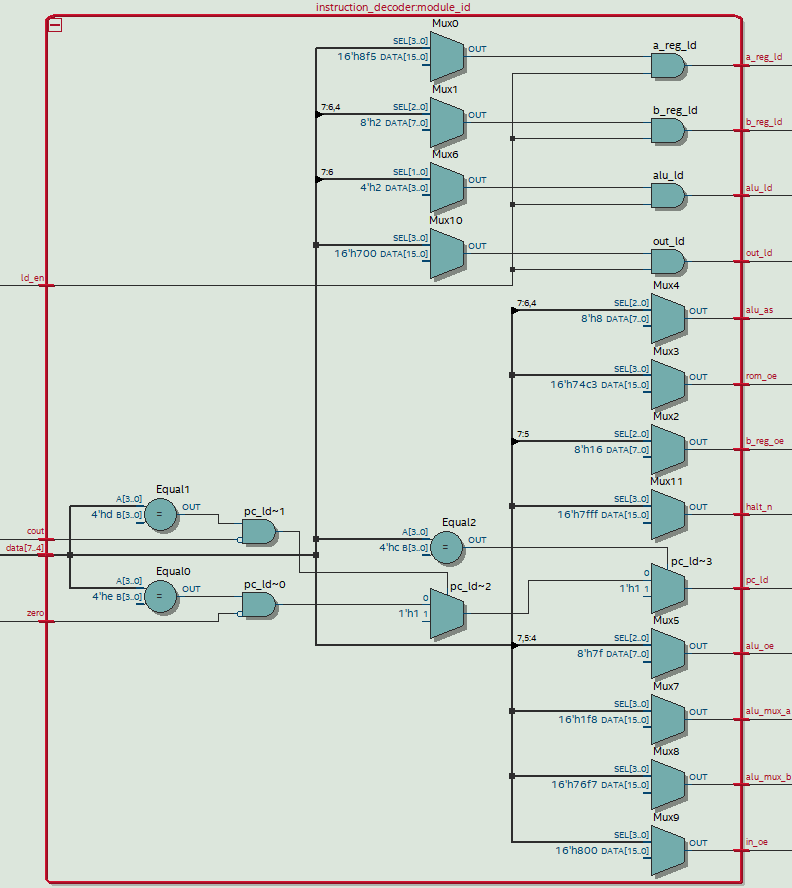
表10「命令デコーダの真理値表(PC_LD以外)」(p.124)、表11「"PC_LD=1"を出力するときの入力の組み合わせ」(p.124)の各表をそのまま書き写した。
ソースコードを見る/隠す
library ieee;
use ieee.std_logic_1164.all;

entity instruction_decoder is
	port(
		data: in std_logic_vector(7 downto 4);

		zero: in std_logic;
		cout: in std_logic;

		ld_en: in std_logic;

		a_reg_ld : out std_logic;
		b_reg_ld : out std_logic;
		b_reg_oe : out std_logic;
		rom_oe   : out std_logic;
		alu_as   : out std_logic;
		alu_oe   : out std_logic;
		alu_ld   : out std_logic;
		alu_mux_a: out std_logic;
		alu_mux_b: out std_logic;
		in_oe    : out std_logic;
		out_ld   : out std_logic;
		halt_n   : out std_logic;

		pc_ld: out std_logic
	);
end entity;

architecture rtl of instruction_decoder is
	subtype ascending_vect_t is std_logic_vector(0 to 11);
	signal truth_tbl: ascending_vect_t;
begin

	with data select
	truth_tbl <=
		ascending_vect_t'("100101001001") when 4d"0",  -- LD A, [Data]
		ascending_vect_t'("010101001001") when 4d"1",  -- LD B, [Data]
		ascending_vect_t'("101001001001") when 4d"2",  -- LD A, B
		ascending_vect_t'("01-001010001") when 4d"3",  -- LD B, A
		ascending_vect_t'("101001111001") when 4d"4",  -- ADD A, B
		ascending_vect_t'("101011111001") when 4d"5",  -- SUB A, B
		ascending_vect_t'("100101111001") when 4d"6",  -- ADD A, [Data]
		ascending_vect_t'("100111111001") when 4d"7",  -- SUB A, [Data]
		ascending_vect_t'("00-001010011") when 4d"8",  -- OUT A
		ascending_vect_t'("001001001011") when 4d"9",  -- OUT B
		ascending_vect_t'("000101001011") when 4d"10", -- OUT [Data]
		ascending_vect_t'("10-00000-101") when 4d"11", -- IN A
		ascending_vect_t'("000101001001") when 4d"12", -- JUMP [Address]
		ascending_vect_t'("000101001001") when 4d"13", -- JNC [Address]
		ascending_vect_t'("000101001001") when 4d"14", -- JNZ [Address]
		ascending_vect_t'("000-0-00-000") when 4d"15", -- HALT
		ascending_vect_t'(12b"0")         when others;

	a_reg_ld  <= truth_tbl(0) and ld_en;
	b_reg_ld  <= truth_tbl(1) and ld_en;
	b_reg_oe  <= truth_tbl(2);
	rom_oe    <= truth_tbl(3);
	alu_as    <= truth_tbl(4);
	alu_oe    <= truth_tbl(5);
	alu_ld    <= truth_tbl(6) and ld_en;
	alu_mux_a <= truth_tbl(7);
	alu_mux_b <= truth_tbl(8);
	in_oe     <= truth_tbl(9);
	out_ld    <= truth_tbl(10) and ld_en;
	halt_n    <= truth_tbl(11);

	pc_ld <=
		'1' when data = 4d"12"                else -- JUMP [Address]
		'1' when data = 4d"13" and cout = '0' else -- JNC [Address]
		'1' when data = 4d"14" and zero = '0' else -- JNZ [Address]
		'0';

end architecture;
2.1.4 ステートマシンを作る
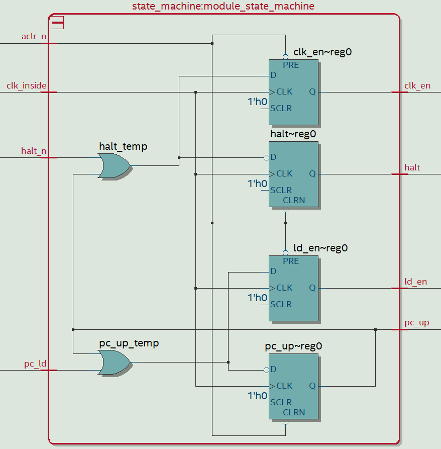
図29「ステート・マシンの内部ブロック図」(p.122)の接続図をそのままVHDLで表現した。
ソースコードを見る/隠す
library ieee;
use ieee.std_logic_1164.all;

entity state_machine is
	port(
		halt_n    : in std_logic;
		pc_ld     : in std_logic;
		clk_inside: in std_logic;
		aclr_n    : in std_logic;

		clk_en: out std_logic;
		halt  : out std_logic;
		pc_up : out std_logic;
		ld_en : out std_logic
	);
end entity;

architecture rtl of state_machine is
	signal halt_temp : std_logic;
	signal pc_up_temp: std_logic;
begin
	process(all)
	begin

		halt_temp  <= halt_n nor pc_up;
		pc_up_temp <= pc_ld  nor pc_up;

		if aclr_n = '0' then
			halt   <= '0';
			clk_en <= '1';
			pc_up  <= '0';
			ld_en  <= '1';

		elsif rising_edge(clk_inside) then
			halt   <=     halt_temp;
			clk_en <= not halt_temp;
			pc_up  <=     pc_up_temp;
			ld_en  <= not pc_up_temp;
		end if;

	end process;
end architecture;
2.1.5 CPUにまとめる
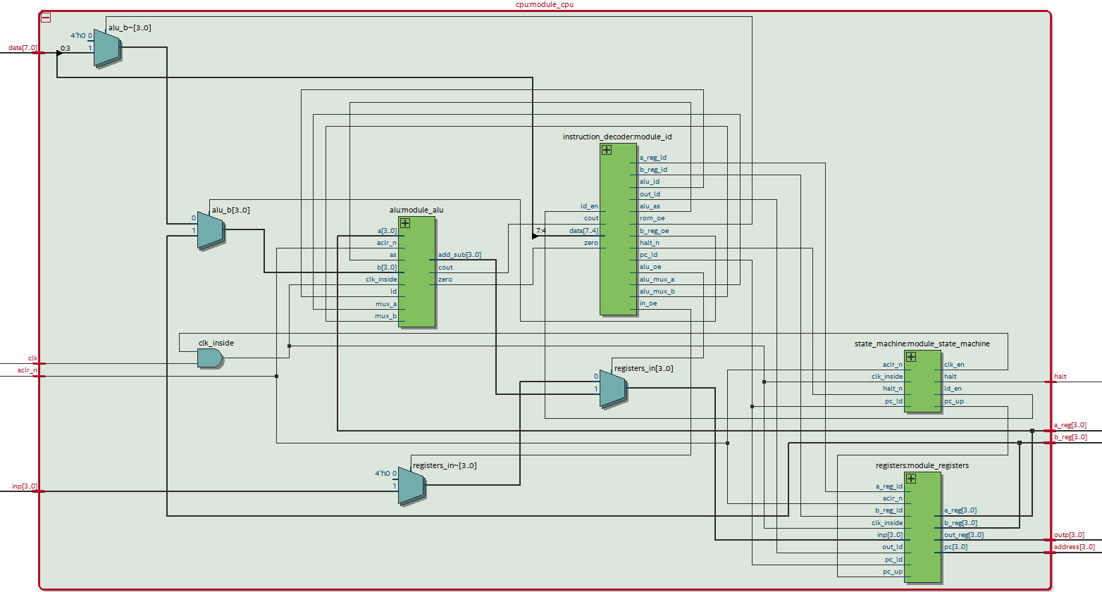
ここまで作ったモジュール同士を配線してCPUを作る。
ソースコードを見る/隠す
library ieee;
use ieee.std_logic_1164.all;

entity cpu is
	port(
		aclr_n : in std_logic;
		inp    : in std_logic_vector(3 downto 0);
		data   : in std_logic_vector(7 downto 0);
		clk    : in std_logic;

		halt   : out std_logic;
		a_reg  : out std_logic_vector(3 downto 0);
		b_reg  : out std_logic_vector(3 downto 0);
		address: out std_logic_vector(3 downto 0);
		outp   : out std_logic_vector(3 downto 0)
	);
end entity;

architecture rtl of cpu is

	signal alu_b     : std_logic_vector(3 downto 0);
	signal alu_mux_a : std_logic;
	signal alu_mux_b : std_logic;
	signal alu_as    : std_logic;
	signal alu_ld    : std_logic;
	signal clk_inside: std_logic;
	signal add_sub   : std_logic_vector(3 downto 0);
	signal zero      : std_logic;
	signal cout      : std_logic;

	signal ld_en    : std_logic;
	signal a_reg_ld : std_logic;
	signal b_reg_ld : std_logic;
	signal b_reg_oe : std_logic;
	signal rom_oe   : std_logic;
	signal alu_oe   : std_logic;
	signal in_oe    : std_logic;
	signal out_ld   : std_logic;
	signal halt_n   : std_logic;
	signal pc_ld    : std_logic;

	signal clk_en: std_logic;
	signal pc_up : std_logic;

	signal registers_in: std_logic_vector(3 downto 0);

	signal a_reg_inside: std_logic_vector(3 downto 0);

begin

	module_alu: entity work.alu
	port map(
		a          => a_reg_inside,
		b          => alu_b,
		mux_a      => alu_mux_a,
		mux_b      => alu_mux_b,
		as         => alu_as,  -- when 0, add; when 1, sub;
		ld         => alu_ld,
		clk_inside => clk_inside,
		aclr_n     => aclr_n, -- 外部へ接続
		add_sub    => add_sub,
		zero       => zero,
		cout       => cout
	);

	module_id:entity work.instruction_decoder
	port map(
		data      => data(7 downto 4), -- 外部へ配線
		zero      => zero,
		cout      => cout,
		ld_en     => ld_en ,
		a_reg_ld  => a_reg_ld,
		b_reg_ld  => b_reg_ld,
		b_reg_oe  => b_reg_oe,
		rom_oe    => rom_oe,
		alu_as    => alu_as,
		alu_oe    => alu_oe,
		alu_ld    => alu_ld,
		alu_mux_a => alu_mux_a,
		alu_mux_b => alu_mux_b,
		in_oe     => in_oe,
		out_ld    => out_ld,
		halt_n    => halt_n,
		pc_ld     => pc_ld
	);

	module_state_machine:entity work.state_machine
	port map(
		halt_n     => halt_n,
		pc_ld      => pc_ld,
		clk_inside => clk_inside,
		aclr_n     => aclr_n, -- 外部へ配線
		clk_en     => clk_en,
		halt       => halt, -- 外部へ配線
		pc_up      => pc_up,
		ld_en      => ld_en
	);

	module_registers:entity work.registers
	port map(
		inp        => registers_in,
		a_reg_ld   => a_reg_ld,
		b_reg_ld   => b_reg_ld,
		out_ld     => out_ld,
		pc_ld      => pc_ld,
		clk_inside => clk_inside,
		aclr_n     => aclr_n, -- 外部へ配線
		pc_up      => pc_up,
		a_reg      => a_reg_inside,
		b_reg      => b_reg,
		out_reg    => outp, -- 外部へ配線
		pc         => address  -- 外部へ配線
	);

	clk_inside <= clk_en and clk;

	-- これがトライステートバッファーから代えたマルチプレクサ
	-- ALUの出力かインポートかいずれかをレジスタ群へ渡す。
	registers_in <=
		add_sub when alu_oe else
		inp     when in_oe  else
		(others => '0');

	-- これもトライステートバッファーから代えたマルチプレクサ
	-- Bレジスタかプログラムメモリーに含まれるオペランドかいずれかをALUへ渡す。
	alu_b <=
		b_reg            when b_reg_oe else
		data(3 downto 0) when rom_oe   else
		(others => '0');

	-- A、Bレジスタも確認のため外へ出す。
	a_reg <= a_reg_inside;
	b_reg <= b_reg;
end architecture;
2.2 クロックジェネレーターを作る
ここで作ったものとまったく同じ。
2.3 ROM (プログラムメモリー)を作る
ここで作ったものとまったく同じ。
2.4 全部組み合わせてCPU1738を完成させる
ソースコードを見る/隠す
library ieee;
use ieee.std_logic_1164.all;

entity cpu1738 is
	port(
		source_clk   : in std_logic;
		manual_clk_in: in std_logic;
		sel          : in std_logic_vector(1 downto 0);
		aclr_n       : in std_logic;
		inp          : in std_logic_vector(3 downto 0);

		halt   : out std_logic;
		a_reg  : out std_logic_vector(3 downto 0);
		b_reg  : out std_logic_vector(3 downto 0);
		outp   : out std_logic_vector(3 downto 0);
		clk_out: out std_logic
	);
end entity;

architecture rtl of cpu1738 is
	signal address      : std_logic_vector(3 downto 0);
	signal data         : std_logic_vector(7 downto 0);
	signal clk_inside   : std_logic;
	signal delayed_clk_0: std_logic;
	signal delayed_clk_1: std_logic;
begin
	module_cpu: entity work.cpu
	port map(
		aclr_n  => aclr_n, -- 外部へ配線
		inp     => inp, -- 外部へ配線
		data    => data,
		clk     => delayed_clk_1,
		halt    => halt, -- 外部へ配線
		a_reg   => a_reg, -- 外部へ配線
		b_reg   => b_reg, -- 外部へ配線
		address => address,
		outp    => outp -- 外部へ配線
	);

	module_clk_gen: entity work.clk_gen
	port map(
		clk           => source_clk,
		manual_clk_in => manual_clk_in,
		sel           => sel,
		clk_out       => clk_inside
	);

	module_rom: entity work.rom
	port map(
		clock   => clk_inside,
		address => address,
		q       => data
	);

	-- 確認のためクロックジェネレーターの出力を外へ出す。
	clk_out <= clk_inside;

	--『CPUの創りかた』のときと同じく、CPUへ与えるクロックを少し遅らせる。
	process(clk_out)
	begin
		if rising_edge(source_clk) then
			delayed_clk_0 <= clk_inside;
			delayed_clk_1 <= delayed_clk_0;
		end if;
	end process;
end architecture;
3. ROM (プログラムメモリー)の初期化ファイルを作る
初期化ファイル(.mif)を生成するためのアセンブラのようなものはPythonで作った。
ソースコードを見る/隠す
def generate_mif(file_name, width, depth, rom):
    f = open(file_name, "w")
    f.write("WIDTH=%d;\n" % width)
    f.write("DEPTH=%d;\n" % depth)
    f.write("ADDRESS_RADIX=UNS;\n")
    f.write("DATA_RADIX=BIN;\n")
    f.write("CONTENT BEGIN\n")
    format_of_code = "0" + str(width) + "b"
    for i in range(depth):
        machine_code = format(rom[i], format_of_code)
        f.write("%10d   :   %s;\n" % (i, machine_code))
    f.write("END;\n")
    f.close()

def LD_A(Data)   : return ( 0 << 4)|(Data & 0xF)    # A ← [Data]
def LD_B(Data)   : return ( 1 << 4)|(Data & 0xF)    # B ← [Data]
def LD_AB()      : return ( 2 << 4)                 # A ← B
def LD_BA()      : return ( 3 << 4)                 # B ← A
def ADD_AB()     : return ( 4 << 4)                 # A ← A + B
def SUB_AB()     : return ( 5 << 4)                 # A ← A - B
def ADD_A(Data)  : return ( 6 << 4)|(Data & 0xF)    # A ← A + [Data]
def SUB_A(Data)  : return ( 7 << 4)|(Data & 0xF)    # A ← A - [Data]
def OUT_A()      : return ( 8 << 4)                 # OUT ← A
def OUT_B()      : return ( 9 << 4)                 # OUT ← B
def OUT(Data)    : return (10 << 4)|(Data & 0xF)    # OUT ← [Data]
def IN_A()       : return (11 << 4)                 # A ← IN
def JUMP(Address): return (12 << 4)|(Address & 0xF) # PC ← [Address]
def JNC(Address) : return (13 << 4)|(Address & 0xF) # PC ← [Address] if NOT Carry
def JNZ(Address) : return (14 << 4)|(Address & 0xF) # PC ← [Address] if NOT Zero
def HALT()       : return (15 << 4)                 # HALT

FILE_NAME = "rom_init.mif"
WIDTH =  8
DEPTH = 16
_ = [0] * DEPTH


# テキストのプログラム例(4)
# インポートとアウトポートとを直結しておく。
# 9/2=4(0100)余り1を計算する。
# 0111(9-2=7)、0101(9-2-2=5)、0011(9-2-2-2=3)、0001(9-2-2-2-2=1)の順に表示されたあと、
# 0100(9/2=4)と表示される。
_[0] = LD_A(9)  # 割られる数
_[1] = LD_B(0)  # 何回引き算ができたかの初期値
_[2] = SUB_A(2) # 割る数(引く数)
_[3] = JNC(10)  # 引いた結果が負なら、ループを抜けて10番地へ
_[4] = OUT_A()  # 今の引き算結果(すなわち余り)を出力して、
_[5] = LD_AB()  # 引き算できた回数をこの3行でインクリメントして、
_[6] = ADD_A(1)
_[7] = LD_BA()
_[8] = IN_A()   # 今の引き算結果(すなわち余り)(今OUTレジスタにある)を読み込んで、
_[9] = JUMP(2)  # 引き算を繰り返す。
_[10] = IN_A()  # (引いた結果が負なら3番地から)余り(今OUTレジスタにある)をAに格納し、
_[11] = OUT_B() # 商(何回引き算ができたか)を出力する。
_[12] = HALT()

generate_mif(FILE_NAME, WIDTH, DEPTH, _)
↓ これが、生成された.mifファイル。
ソースコードを見る/隠す
WIDTH=8;
DEPTH=16;
ADDRESS_RADIX=UNS;
DATA_RADIX=BIN;
CONTENT BEGIN
         0   :   00001001;
         1   :   00010000;
         2   :   01110010;
         3   :   11011010;
         4   :   10000000;
         5   :   00100000;
         6   :   01100001;
         7   :   00110000;
         8   :   10110000;
         9   :   11000010;
        10   :   10110000;
        11   :   10010000;
        12   :   11110000;
        13   :   00000000;
        14   :   00000000;
        15   :   00000000;
END;
4. 動かしてみる
9/2=4余り1を計算する。右から4ビットずつ、Bレジスタ、Aレジスタ、一番左がOUTレジスタ。OUTレジスタに7、5、3、1の順に表示されて、最後に商4が表示される。余り1がAレジスタに表示される。
5. ファイル一式
https://github.com/ti-nspire/VHDL_for_Quartus_Prime/tree/main/CPU1738
6. 参考


