1. 概要
一部を除いて極力忠実にテキストの回路をVHDLで書き換える。変更点は下のとおりである。
- 命令デコーダーはHDLらしく真理値表として記述する。
- ROM (プログラムメモリー)はMAX10内にメモリーブロックとして独立させる。
- 1Hz、10Hzのクロックは、使用した評価ボードに実装されている48MHzクロック(MAX10の27番ピンに配線されている)をFPGA内で分周して生成する。
- マニュアルクロック用のディバウンス回路もFPGAで作る。
- リセット回路は単にタクトスイッチでLoにするだけにする。バウンスに対しては何もしない。
MAX10 (10M08SAE144C8G)の評価ボードはマルツ製のこれを使う(参考: 『MAX10実験キットで学ぶFPGA&コンピュータ』圓山宗智、CQ出版)。
(追記: 2021年12月29日現在、マルツオンラインでは販売終了であったが、マルツオンライン楽天市場店では買えた)
(再追記: 2022年01月09日現在、マルツオンライン楽天市場店でも販売が終了した)
2. モジュールごとに作ってゆく
Quartus Primeの[Assignments]メニューから[Settings] → [Compiler Settings] → [VHDL Input]の順に選択し、[VHDL version]フィールドにある[VHDL 2008]ラジオボタンをオンにしておく。
2.1 CPUを作る
2.1.1 ALU部を作る
『CPUの創りかた』のALUは単なる4ビット加算器である。ここではテキストと同じく74283のようなものを作る。キャリーインは使わないが練習なので実装しておく。キャリーアウトを得たいので、各オペランドを5ビットに拡張してから足し合わせる。
コードを見る/隠す
library ieee;
use ieee.std_logic_1164.all;
use ieee.numeric_std.all;

entity generic_74283 is
	generic(
		NUM_BITS: natural := 4
	);
	port(
		cin: in std_logic;
		a  : in std_logic_vector(NUM_BITS-1 downto 0);
		b  : in std_logic_vector(NUM_BITS-1 downto 0);

		sum : out std_logic_vector(NUM_BITS-1 downto 0);
		cout: out std_logic
	);
end entity;

architecture rtl of generic_74283 is
	-- 和の假置き信号。キャリーアウトを得たいので1ビット拡張して5ビット幅。
	signal temp_sum: unsigned(NUM_BITS downto 0);
begin
	-- キャリーアウトを得たいので1ビット拡張して5ビット幅にしてから足し合わせる。
	-- どのオペランドも長さは最長オペランドに合わせて拡張される。
	-- Quartus Prime Liteではシングルビットが加算できなかったので('0' & cin)のようにベクタにした。
	temp_sum <= ('0' & unsigned(a)) + unsigned(b) + ('0' & cin);

	-- 和だけを抜いて返す。
	sum <= std_logic_vector(temp_sum)(NUM_BITS-1 downto 0);

	-- キャリーアウトだけを抜いて返す。
	cout <= temp_sum(NUM_BITS);
end architecture;
2.1.2 命令デコーダー部をつくる
HDLらしく真理値表(p.242)をそのまま書き写す。p.242の時点ではCフラグのロジックがHi有意になっているが、最適化された最終的な回路(p.272)ではLo有意になっているので、下のコードもそれに合わせた。
コードを見る/隠す
library ieee;
use ieee.std_logic_1164.all;

entity instruction_decoder is
	port(
		c_flag_n: in std_logic;
		op_code : in std_logic_vector(3 downto 0);

		-- "00"のときA_REGを選択、"01"のときB_REGを選択、"10"のときINポートを選択
		sel: out std_logic_vector(1 downto 0);

		-- "1110"のときA_REGにロード、"1101"のときB_REGにロード、
		-- "1011"のときOUT_REGにロード、"0111"のときPCにロード
		load_n: out std_logic_vector(3 downto 0)
	);
end entity;

architecture rtl of instruction_decoder is
	signal load_n_sel: std_logic_vector(5 downto 0);
begin

	-- ページ242の真理値表を書き写す。
	-- 最適化された最終的な回路に合わせてc_flagは反転してc_flag_nにした。
	load_n_sel <= "1110" & "00" when op_code = "0000" else -- ADD A, Im
	              "1110" & "01" when op_code = "0001" else -- MOV A, B
	              "1110" & "10" when op_code = "0010" else -- IN A
	              "1110" & "11" when op_code = "0011" else -- MOV A, Im
	              "1101" & "00" when op_code = "0100" else -- MOV B, A
	              "1101" & "01" when op_code = "0101" else -- ADD B, Im
	              "1101" & "10" when op_code = "0110" else -- IN B
	              "1101" & "11" when op_code = "0111" else -- MOV B, Im
	              "1011" & "01" when op_code = "1001" else -- OUT B
	              "1011" & "11" when op_code = "1011" else -- OUT Im
	              "0111" & "11" when op_code = "1110" and c_flag_n = '1' else -- JNC (C=0)
	              "1111" & "--" when op_code = "1110" and c_flag_n = '0' else -- JNC (C=1)
	              "0111" & "11" when op_code = "1111" else -- JMP
	              "----" & "--" ; -- 必ずデフォルトを記述する。

	-- A、B、OUTの各レジスタおよびPCへ与える!ロード信号を抜いて返す。
	load_n <= load_n_sel(5 downto 2);

	-- マルチプレクサへ与えるセレクト信号を抜いて返す。
	sel <= load_n_sel(1 downto 0);

/*
	-- 最適化された回路(ページ272)をVHDLで表現した例
	sel(1) <= op_code(1);
	sel(0) <= op_code(0) or op_code(3);

	load_n(0) <= op_code(2) or op_code(3);
	load_n(1) <= (not op_code(2)) or op_code(3);
	load_n(2) <= (not op_code(2)) nand op_code(3);
	load_n(3) <= not((c_flag_n or op_code(0)) and op_code(2) and op_code(3));
*/

end architecture;
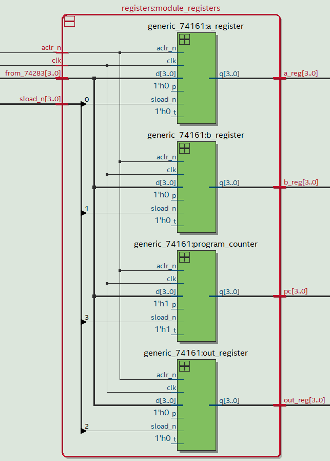
2.1.3 A、B、OUTの各レジスタとPCとを作る
2.1.3.1 まず74161のようなものを作る
まずテキストと同じく74161のようなものを共通部品として作っておく。74161は同期カウンター(!非同期リセット、!同期ロード、カウントイネーブル、リプルキャリーアウト)である。リプルキャリーは使わないが練習なので実装しておく。74161を複数使ってビット幅を4の倍数にしたいときは、リプルキャリーアウトを次段の74161のt端子に接続する。
コードを見る/隠す
library ieee;
use ieee.std_logic_1164.all;
use ieee.numeric_std.all;

entity generic_74161 is
	generic(
		NUM_BITS: natural := 4
	);
	port(
		clk    : in std_logic;
		aclr_n : in std_logic; -- aはasynchronousの意味
		sload_n: in std_logic; -- sはsynchronousの意味
		d      : in std_logic_vector(NUM_BITS-1 downto 0);

		p: in std_logic;
		t: in std_logic;

		q  : out std_logic_vector(NUM_BITS-1 downto 0);
		rco: out std_logic -- リプルキャリーアウト
	);
end entity;

architecture rtl of generic_74161 is
	signal count: natural range 0 to 2**NUM_BITS - 1; -- この信号をカウンターとして使う。
	constant COUNT_MAX: natural := 2**NUM_BITS - 1;   -- カウンターのトップ値。
begin
	-- カウント値をそのまま出力する。
	q <= std_logic_vector(to_unsigned(count, NUM_BITS));

	-- リプルキャリーアウト機能(出力の全ビットに1が立っている間、1を出力する)を実装する。
	rco <= '1' when t = '1' and count >= COUNT_MAX else '0';

	process(all)
	begin

		-- !非同期リセット
		if aclr_n = '0' then
			count <= 0;

		elsif rising_edge(clk) then

			-- !同期ロード
			if sload_n = '0' then
				count <= to_integer(unsigned(d));

			-- 同期カウント
			elsif p and t then
				if count >= COUNT_MAX then -- カウンターのトップ値に達していたら0にロールオーバーする。
					count <= 0;
				else
					count <= count + 1; -- カウンターのトップ値に達していなかったらカウントアップする。
				end if;
			end if;
		end if;
	end process;

end architecture;
2.1.3.2 74161のようなものを4つまとめて実体化する
コードを見る/隠す
library ieee;
use ieee.std_logic_1164.all;

entity registers is
	generic(
		NUM_BITS: natural := 4
	);
	port(
		clk   : in std_logic;
		aclr_n: in std_logic;

		-- "1110"のときA_REGにロード、"1101"のときB_REGにロード、
		-- "1011"のときOUT_REGにロード、"0111"のときPCにロード
		sload_n: in std_logic_vector(NUM_BITS-1 downto 0);

		from_74283: in std_logic_vector(NUM_BITS-1 downto 0);

		a_reg  : out std_logic_vector(NUM_BITS-1 downto 0);
		b_reg  : out std_logic_vector(NUM_BITS-1 downto 0);
		out_reg: out std_logic_vector(NUM_BITS-1 downto 0);
		pc     : out std_logic_vector(NUM_BITS-1 downto 0)
	);
end entity;

architecture rtl of registers is
begin
	-- A_REGを実体化
	a_register: entity work.generic_74161
		generic map(NUM_BITS => NUM_BITS)
		port map(
			clk     => clk,
			aclr_n  => aclr_n,
			sload_n => sload_n(0),
			d       => from_74283,
			p=>'0',t=>'0', -- カウンターを無効化
			q       => a_reg
		);

	-- B_REGを実体化
	b_register: entity work.generic_74161
		generic map(NUM_BITS => NUM_BITS)
		port map(
			clk     => clk,
			aclr_n  => aclr_n,
			sload_n => sload_n(1),
			d       => from_74283,
			p=>'0',t=>'0',  -- カウンターを無効化
			q       => b_reg
		);

	-- OUT_REGを実体化
	out_register: entity work.generic_74161
		generic map(NUM_BITS => NUM_BITS)
		port map(
			clk     => clk,
			aclr_n  => aclr_n,
			sload_n => sload_n(2),
			d       => from_74283,
			p=>'0',t=>'0',  -- カウンターを無効化
			q       => out_reg
		);

	-- PCを実体化
	program_counter: entity work.generic_74161
		generic map(NUM_BITS => NUM_BITS)
		port map(
			clk     => clk,
			aclr_n  => aclr_n,
			sload_n => sload_n(3),
			d       => from_74283,
			p=>'1',t=>'1',  -- カウンターを有効化
			q       => pc
		);

end architecture;
2.1.4 マルチプレクサを作る
テキストは74153を2個束ねているが、ここでは4ビット × 3本のうち1本を選ぶマルチプレクサを一から作る。練習なので、74153のようなストローブ機能も実装しておく。
コードを見る/隠す
-- 複数のstd_logic_vectorから成る排列型を定義する。
-- ここでしか使わない型なので別ファイルに分けなかった。
library ieee;
use ieee.std_logic_1164.all;
package typedef_pkg is
	type array_slv is array(natural range <>) of std_logic_vector;
end package;
----------------------------------------------------------------------

library ieee;
use ieee.std_logic_1164.all;
use ieee.numeric_std.all;
use work.typedef_pkg.all;

entity generic_multiplexer is
	generic(
		NUM_BITS    : natural := 4;
		NUM_WORDS   : natural := 3;
		NUM_SEL_BITS: natural := 2  -- ceil(log2(NUM_WORDS))
	);
	port(
		sel   : in std_logic_vector(NUM_SEL_BITS-1 downto 0 );
		inp   : in array_slv(0 to NUM_WORDS-1)(NUM_BITS-1 downto 0);
		strobe: in std_logic; -- Hiのときに強制的に出力を全部Loにする。

		outp: out std_logic_vector(NUM_BITS-1 downto 0)
	);
end entity;

architecture rtl of generic_multiplexer is
begin

	process(all)
		variable which_word: natural;
	begin

		-- ストローブ機能
		if strobe = '1' then
			outp <= (others => '0');

		-- マルチプレクサ機能。
		-- セレクト信号に応じて、どの入力を出力するのかを選択する。
		else
			which_word := to_integer(unsigned(sel));
			case which_word is
				when 0 to NUM_WORDS-1 => outp <= inp(which_word); -- which_wordは要するに排列のインデックス
				when others           => outp <= (others => '0');
			end case;
		end if;
	end process;

end architecture;
2.1.5 CPUにまとめる
これまでにつくったモジュール同士を配線してCPUを作る。
コードを見る/隠す
library ieee;
use ieee.std_logic_1164.all;

entity cpu is
	port(
		clk   : in std_logic;
		aclr_n: in std_logic;
		inp   : in std_logic_vector(3 downto 0); -- INポート
		data  : in std_logic_vector(7 downto 0); -- ROM (プログラムメモリー)から与えられる命令+オペランド。

		a_reg  : out std_logic_vector(3 downto 0); -- 確認として信号が出力できるよう端子を設けておく。
		b_reg  : out std_logic_vector(3 downto 0); -- 確認として信号が出力できるよう端子を設けておく。
		outp   : out std_logic_vector(3 downto 0); -- OUTポート
		address: out std_logic_vector(3 downto 0) -- ROM (プログラムメモリー)へ与えるアドレス。
	);
end entity;

architecture rtl of cpu is
	-- モジュール同士を配線するための内部信号
	signal load_n      : std_logic_vector(3 downto 0);
	signal adder_reg   : std_logic_vector(3 downto 0);
	signal a_reg_inside: std_logic_vector(3 downto 0);
	signal b_reg_inside: std_logic_vector(3 downto 0);
	signal mux_adder_a : std_logic_vector(3 downto 0);
	signal cout        : std_logic;
	signal sel         : std_logic_vector(1 downto 0);
	signal c_flag_n    : std_logic;
begin

	-- A、B、OUTの各レジスタおよびPCを実体化
	module_registers: entity work.registers
		port map(
			clk        => clk,    -- 外部へ配線
			aclr_n     => aclr_n, -- 外部へ配線
			sload_n    => load_n,
			from_74283 => adder_reg,
			a_reg      => a_reg_inside,
			b_reg      => b_reg_inside,
			out_reg    => outp,   -- 外部へ配線
			pc         => address -- 外部へ配線
		);

	-- ALUを実体化
	module_adder: entity work.generic_74283
		port map(
			cin  => '0',
			a    => mux_adder_a,
			b    => data(3 downto 0), -- 外部へ配線
			sum  => adder_reg,
			cout => cout
		);

	-- 命令デコーダーを実体化
	module_id: entity work.instruction_decoder
		port map(
			c_flag_n => c_flag_n,
			op_code  => data(7 downto 4), -- 外部へ配線
			sel      => sel,
			load_n   => load_n
		);

	-- マルチプレクサを実体化
    module_mux: entity work.generic_multiplexer
        port map(
            sel => sel,
            inp(0) => a_reg_inside,
            inp(1) => b_reg_inside,
            inp(2) => inp, -- 外部へ配線
            strobe => '0',
            outp   => mux_adder_a
        );

	-- ALU (ここでは加算器)のキャリーアウトはDFFに1回通してから命令デコーダーへ渡す。
	-- テキストで言えば7474の回路である。
	process(clk)
	begin
		if rising_edge(clk) then
			c_flag_n <= not cout;
		end if;
	end process;

	-- 確認のためA、Bレジスタも外へ出しておく。
	a_reg <= a_reg_inside; -- 外部へ配線
	b_reg <= b_reg_inside; -- 外部へ配線

end architecture;
2.2 クロックジェネレーターを作る
2.2.1 1Hz、10Hzのクロック生成回路を作る
カウンターのオーバーフローするたびに出力をトグルしてクロックを生成する。セレクト信号に応じてカウンターのトップ値を入れ換えることで2種類のクロックが生成できるようにした。
コードを見る/隠す
library ieee;
use ieee.std_logic_1164.all;
use ieee.numeric_std.all;

entity auto_clk is
	generic(
		F_CLK  : natural := 48_000_000;
		FREQ_LO: natural := 1;
		FREQ_HI: natural := 10
	);
	port(
		clk    : in  std_logic;
		sel    : in  std_logic; -- 0のときFREQ_LOを出力、1のときFREQ_HIを出力
		clk_out: out std_logic
	);
end entity;

architecture rtl of auto_clk is
begin

	process(all)
		variable count_max: natural range 0 to F_CLK/2-1;
		variable counter  : natural range 0 to F_CLK/2-1 := 0;
	begin

		case sel is -- セレクト信号に応じてカウンターのトップ値を入れ換える。
			when '0'    => count_max := F_CLK/(FREQ_LO*2)-1;
			when '1'    => count_max := F_CLK/(FREQ_HI*2)-1;
			when others => count_max := F_CLK/2-1; -- 1 Hz
		end case;

		-- カウンター
		if rising_edge(clk) then
			if counter >= count_max then -- オーバーフローするたびに
				clk_out <= not clk_out;   -- 出力をトグルする。
				counter := 0;
			else
				counter := counter + 1;
			end if;
		end if;
	end process;

end architecture;
2.2.2 マニュアルクロック用のディバウンス回路を作る
入力Hi、出力Loの状態が一定時間(下の例では15ミリ秒)続いたらバウンスが収まったと判断して出力をHiにし、逆に入力Lo、出力Hiの状態が一定時間続いたら同じように出力をLoにする、という回路である。generic()のIS_INVERTEDで極性を反転できるようにしておいた。
コードを見る/隠す
library ieee;
use ieee.std_logic_1164.all;
use ieee.numeric_std.all;

entity debouncer is
	generic(
		F_CLK      : natural := 48_000_000;
		BOUNCE_msec: natural := 15;   -- 想定されるバウンス時間(ミリ秒単位)
		IS_INVERTED: boolean := false -- 極性を反転するかしないか
	);
	port(
		clk         : in  std_logic;
		bounce_in   : in  std_logic;
		debounce_out: out std_logic
	);
end entity;

architecture rtl of debouncer is
	-- 想定されるバウンス時間までカウントするためのカウンターのトップ値。厳密に設定する必要はない。
	constant COUNT_MAX: natural := F_CLK * BOUNCE_msec/1000 - 1;

	-- 入力信号を同期化したあとの信号
	signal in_reg: std_logic;
begin

	process(clk)
		variable count: natural := 0;
	begin
		if rising_edge(clk) then
			-- 入力信号を同期化する。省いてもよい。
			-- 必要に応じて極性を反転する。
			case IS_INVERTED is
				when false  => in_reg <=     bounce_in;
				when true   => in_reg <= not bounce_in;
				when others => in_reg <=     bounce_in;
			end case;

			-- 入出力のロジックが一致している限り(バウンスが原因で偶然一致した場合も含む)、
			-- カウンターをリセットし続ける。
			if debounce_out = in_reg then
				count := 0;
			else
				count := count + 1;
			end if;

		-- 入出力のロジックの不一致状態が一定時間以上継続したら出力をトグルする。
		elsif falling_edge(clk) then
			if count >= COUNT_MAX then
				debounce_out <= not debounce_out;
			end if;
		end if;
	end process;

end architecture;
2.2.3 クロックジェネレーターとしてまとめる
これまでに作った1Hz、10Hzのクロック生成回路とディバウンサーとをひとつにまとめる。マニュアルクロックについては、タクトスイッチを押したときにHiを出力、放したときにLoを出力するようにしたいので、ディバウンサーのIS_INVERTEDはtrueにする。
コードを見る/隠す
library ieee;
use ieee.std_logic_1164.all;

entity clk_gen is
	generic(
		F_CLK: natural := 48_000_000;

		FREQ_LO: natural := 1;
		FREQ_HI: natural := 10
	);
	port(
		clk          : in  std_logic;
		manual_clk_in: in  std_logic;
		sel          : in  std_logic_vector(1 downto 0);

		clk_out: out std_logic
	);
end entity;

architecture rtl of clk_gen is
	signal manual_signal: std_logic;
	signal auto_signal  : std_logic;
begin

	-- ディバウンサーを実体化
	manual: entity work.debouncer
		generic map(
			F_CLK       => F_CLK,
			BOUNCE_msec => 15,
			IS_INVERTED => true
		)
		port map(
			clk          => clk,
			bounce_in    => manual_clk_in,
			debounce_out => manual_signal
		);

	-- 1Hz、10Hzクロック生成器を実体化
	auto: entity work.auto_clk
		generic map(
			F_CLK   => F_CLK,
			FREQ_LO => FREQ_LO,
			FREQ_HI => FREQ_HI
		)
		port map(
			clk     => clk,
			sel     => sel(1), -- 0のときFREQ_LOを、1のときFREQ_HIを出力
			clk_out => auto_signal
		);

	process(all)
	begin
		if rising_edge(clk) then
			case sel is
				when "00"      => clk_out <= manual_signal; -- セレクト信号が"00"のとき手動クロックを出力
				when "01"|"10" => clk_out <= auto_signal; -- "01"のときFREQ_LOを、"10"のときFREQ_HIを出力
				when others    => clk_out <= '0'; -- それ以外のときはクロック停止
			end case;
		end if;
	end process;

end architecture;
2.3 ROM (プログラムメモリー)を作る
IPカタログを利用してROM本体(8ビット × 16本)のVHDLを自動生成する。自動生成の方法
は、ここの手順4以降を参照。
コードを見る/隠す
LIBRARY ieee;
USE ieee.std_logic_1164.all;

LIBRARY altera_mf;
USE altera_mf.altera_mf_components.all;

ENTITY rom IS
	PORT(
		address: IN  STD_LOGIC_VECTOR(3 DOWNTO 0);
		clock  : IN  STD_LOGIC := '1';
		q      : OUT STD_LOGIC_VECTOR(7 DOWNTO 0)
	);
END rom;

ARCHITECTURE SYN OF rom IS
	SIGNAL sub_wire0: STD_LOGIC_VECTOR(7 DOWNTO 0);
BEGIN
	q <= sub_wire0(7 DOWNTO 0);

	altsyncram_component: altsyncram
	GENERIC MAP(
		address_aclr_a         => "NONE",
		clock_enable_input_a   => "BYPASS",
		clock_enable_output_a  => "BYPASS",
		init_file              => "rom_init.mif", -- これがROM (プログラムメモリー)の初期化ファイル
		intended_device_family => "MAX 10",
		lpm_hint               => "ENABLE_RUNTIME_MOD=NO",
		lpm_type               => "altsyncram",
		numwords_a             => 16,
		operation_mode         => "ROM",
		outdata_aclr_a         => "NONE",
		outdata_reg_a          => "UNREGISTERED",
		widthad_a              => 4,
		width_a                => 8,
		width_byteena_a        => 1
	)
	PORT MAP(
		address_a => address,
		clock0    => clock,
		q_a       => sub_wire0
	);

END SYN;
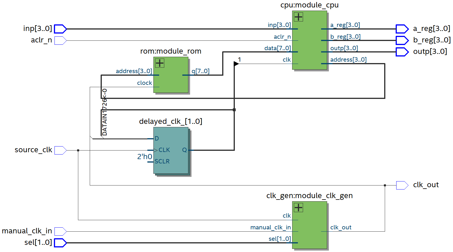
2.4. 全体を配線してTD4を完成させる
ROMのアドレスバスにDFFが入っているため、何もしないと、CPUにクロックが入った時点ではROMからCPUへ命令が届かない。解決する手段として、CPUへ与えるクロックをDFFに2回通して遅らせた(3回でも4回でも何回でもよい)。
コードを見る/隠す
library ieee;
use ieee.std_logic_1164.all;

entity td4 is
	generic(
		F_CLK  : natural := 48_000_000;
		FREQ_LO: natural := 1;
		FREQ_HI: natural := 10
	);
	port(
		aclr_n       : in std_logic;
		inp          : in std_logic_vector(3 downto 0);
		source_clk   : in std_logic;
		manual_clk_in: in std_logic;
		sel          : in std_logic_vector(1 downto 0);

		a_reg  : out std_logic_vector(3 downto 0);
		b_reg  : out std_logic_vector(3 downto 0);
		outp   : out std_logic_vector(3 downto 0);
		clk_out: out std_logic
	);
end entity;

architecture rtl of td4 is
	-- モジュール同士を配線するための内部信号
	signal clk_inside   : std_logic;
	signal delayed_clk_0: std_logic;
	signal delayed_clk_1: std_logic;
	signal data         : std_logic_vector(7 downto 0);
	signal address      : std_logic_vector(3 downto 0);
begin
	-- クロックジェネレーターを実体化
	module_clk_gen: entity work.clk_gen
		generic map(
			F_CLK   => F_CLK,
			FREQ_LO => FREQ_LO,
			FREQ_HI => FREQ_HI
		)
		port map(
			clk           => source_clk,    -- 外部へ配線
			manual_clk_in => manual_clk_in, -- 外部へ配線
			sel           => sel,           -- 外部へ配線
			clk_out       => clk_inside
		);

	-- CPUを実体化
	module_cpu: entity work.cpu
		port map(
			clk     => delayed_clk_1,
			aclr_n  => aclr_n, -- 外部へ配線
			inp     => inp,    -- 外部へ配線
			data    => data,
			a_reg   => a_reg,  -- 外部へ配線
			b_reg   => b_reg,  -- 外部へ配線
			outp    => outp,   -- 外部へ配線
			address => address
		);

	-- ROM (プログラムメモリー)を実体化
	module_rom: entity work.rom
		port map(
			address => address,
			q       => data,
			clock   => clk_inside
		);

   -- ROMへ与えるクロックよりもCPUへ与えるクロックを遅らせるためDFFに2回通す。
	process(source_clk)
	begin
		if rising_edge(source_clk) then
			delayed_clk_0 <= clk_inside;
			delayed_clk_1 <= delayed_clk_0;
		end if;
	end process;

   -- 確認用としてクロックを出力できるようにしておく。
	clk_out <= clk_inside;
end architecture;
3. ROMの初期化ファイル(.mif)を作る
アセンブラのようなものをPythonで作る。生成する.mifファイル名およびその配置場所については、ROMを作るときに指定したファイル名、配置場所に合わせる。
コードを見る/隠す
def generate_mif(file_name, width, depth, rom):
    f = open(file_name, "w")
    f.write("WIDTH=%d;\n" % width)
    f.write("DEPTH=%d;\n" % depth)
    f.write("ADDRESS_RADIX=UNS;\n")
    f.write("DATA_RADIX=BIN;\n")
    f.write("CONTENT BEGIN\n")
    format_of_code = "0" + str(width) + "b"
    for i in range(depth):
        machine_code = format(rom[i], format_of_code)
        f.write("%10d   :   %s;\n" % (i, machine_code))
    f.write("END;\n")
    f.close()

def MOV_A(Im): return ( 3 << 4) | (Im & 0xF) # AレジスタにImを転送
def MOV_B(Im): return ( 7 << 4) | (Im & 0xF) # BレジスタにImを転送
def MOV_AB() : return ( 1 << 4)              # AレジスタにBレジスタを転送
def MOV_BA() : return ( 4 << 4)              # BレジスタにAレジスタを転送
def ADD_A(Im): return ( 0 << 4) | (Im & 0xF) # AレジスタにImを加算
def ADD_B(Im): return ( 5 << 4) | (Im & 0xF) # BレジスタにImを加算
def IN_A()   : return ( 2 << 4)              # 入力ポートからAレジスタへ転送
def IN_B()   : return ( 6 << 4)              # 入力ポートからBレジスタへ転送
def OUT(Im)  : return (11 << 4) | (Im & 0xF) # 出力ポートへImを転送
def OUT_B()  : return ( 9 << 4)              # 出力ポートへBレジスタを転送
def JMP(Im)  : return (15 << 4) | (Im & 0xF) # Im番地へジャンプ
def JNC(Im)  : return (14 << 4) | (Im & 0xF) # Cフラグが1ではないときにIm番地へジャンプ

FILE_NAME = "rom_init.mif"
WIDTH =  8
DEPTH = 16
_ = [0] * DEPTH

# クロックは1 Hzにする。
pc = -1
_[(pc:=pc+1)] = OUT(0b0111) # LEDを3つ点灯

jump_where_0 = pc+1
_[(pc:=pc+1)] = ADD_A(1)
_[(pc:=pc+1)] = JNC(jump_where_0) # 16回ループ

jump_where_1 = pc+1
_[(pc:=pc+1)] = ADD_A(1)
_[(pc:=pc+1)] = JNC(jump_where_1) # 16回ループ

_[(pc:=pc+1)] = OUT(0b0110) # LEDを2つ点灯

jump_where_2 = pc+1
_[(pc:=pc+1)] = ADD_A(1)
_[(pc:=pc+1)] = JNC(jump_where_2) # 16回ループ

jump_where_3 = pc+1
_[(pc:=pc+1)] = ADD_A(1)
_[(pc:=pc+1)] = JNC(jump_where_3) # 16回ループ

jump_where_4 = pc+1
_[(pc:=pc+1)] = OUT(0b0000)
_[(pc:=pc+1)] = OUT(0b0100)
_[(pc:=pc+1)] = ADD_A(1)
_[(pc:=pc+1)] = JNC(jump_where_4) # LED点滅を16回ループ

_[(pc:=pc+1)] = OUT(0b1000) # LEDを1つ点灯
_[(pc:=pc+1)] = JMP(pc+1) # ここにとどまる。

generate_mif(FILE_NAME, WIDTH, DEPTH, _)
生成された.mifファイル:
コードを見る/隠す
WIDTH=8;
DEPTH=16;
ADDRESS_RADIX=UNS;
DATA_RADIX=BIN;
CONTENT BEGIN
         0   :   10110111;
         1   :   00000001;
         2   :   11100001;
         3   :   00000001;
         4   :   11100011;
         5   :   10110110;
         6   :   00000001;
         7   :   11100110;
         8   :   00000001;
         9   :   11101000;
        10   :   10110000;
        11   :   10110100;
        12   :   00000001;
        13   :   11101010;
        14   :   10111000;
        15   :   11111111;
END;
4. 動かしてみる
先に.mifファイルを生成してから全体をコンパイルする。ここでは、テキストのラーメンタイマー(3分15秒タイマー)を10Hzで動かしている。だから19.5秒タイマーである。
右から4ビットずつ、Bレジスタ、Aレジスタ、一番左の4ビットがOUTレジスタ。
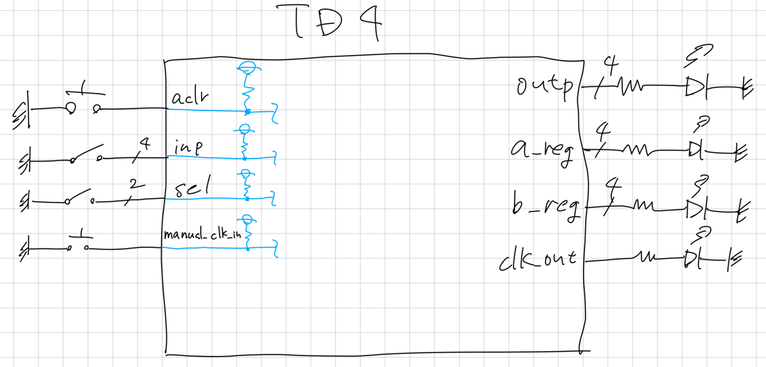
入力は全部、FPGA側で内部プルアップした。5. ファイル一式
https://github.com/ti-nspire/VHDL_for_Quartus_Prime/tree/main/TD4
6. 参考
補遺A.
.mifファイルを入れ換えたときにフルコンパイルし直す必要はなかった。


