はじめに
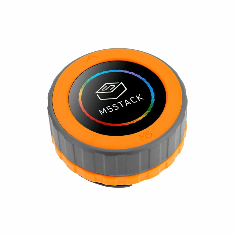
本記事では、M5Dialを用いてUnit-Roller485を制御する。
目的
M5Dialをダイヤルとして使用し、I2C通信を用いてRoller485の制御を行う。
準備物
○ハードウェア系
- PC(Windows10)
- M5Dial
- Unit-Roller485
- USB Type-Cケーブル(PC-M5Stack接続用)
○ソフトウェア系
- Arduino IDE
→インストールについては、こちらを参照とする。
接続準備
事前準備として、
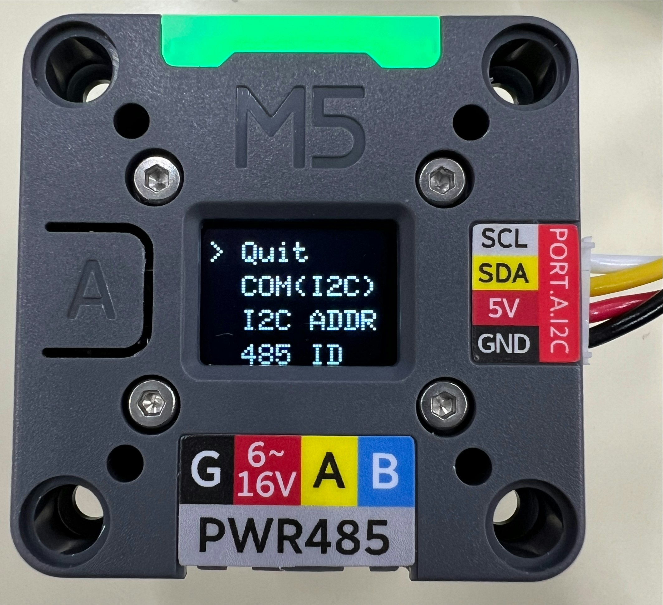
- Roller485の通信設定をI2C通信に変更する。
- I2C通信時のRoller485のアドレスを確認する。
→筆者環境については、「0x40」を使用。
※上記2項目の確認についてはRoller485電源投入時に、背面にあるボタンを押下しながら電源を投入することで、設定画面を確認することができる。(確認画面を以下に示す。)

- M5Stack Tab5のI2C通信用ピン(SDA・SCL)が何番かを確認する。
→「SDA:13・SCL:15」をそれぞれ使用する。
実行スクリプト
Roller485 通信プロトコル(I2C通信用)を参考にコマンドを送信する。
動作としては、
- スイッチによるモータのON/OFF切り替え
- ダイヤルによるモータ回転速度の調整・方向変更(エンコーダ値使用)
となる。
本記事で実際に使用したソースコードを以下に示す。
※ボードは「M5Stamp S3」を選択する。
m5tab5_motorControl.ino
// ----------------------------------------------------------------------------------------------------
// ライブラリの読込
#include "M5Dial.h"
#include <Wire.h>

// ----------------------------------------------------------------------------------------------------
// マクロの定義

// ON/OFF
#define ON  true
#define OFF false
#define CW  true
#define CCW false

// I2C通信
#define ROLLER_ADDRESS 0x40  // Unit-Roller485 I2Cアドレス
#define I2C_SDA        13    // M5Dial I2C通信ポート(SDA)
#define I2C_SCL        15    // M5Dial I2C通信ポート(SCL)

#define MAX_SPEED 1000  // 最大回転速度[rpm]

// ----------------------------------------------------------------------------------------------------
// グローバル変数・定数の定義

// スイッチ状態
bool motor_sw_state  = OFF;
bool rotate_sw_state = CCW;

// モータ回転速度
int32_t motor_speed = 100;
uint8_t motor_bytes[4] = {0, 0, 0, 0};


// ----------------------------------------------------------------------------------------------------
// 関数の定義

// int32 --> byteに変換(Roller485-Unit用)
void cvtInt2Bytes(void) {
  uint32_t remainder = motor_speed * 100;  // コマンド変換用にx100
  // char speed_str[4];  // デバッグ用

  for(int i = 0; i < 4; i++) {
    if (rotate_sw_state) {
      motor_bytes[i] = remainder % 256;  // CW
    }
    else {
      motor_bytes[i] = ~(remainder % 256);  // CCW
    }
    remainder /= 256;
  }
}

// モータON/OFF切替
void motorSW() {
  uint8_t on_command[2]  = {0x00, 0x01};  // モータONコマンド
  uint8_t off_command[2] = {0x00, 0x00};  // モータOFFコマンド

  uint8_t length = 2;  // コマンド長

  if (motor_sw_state) {
    // ON --> OFF
    motor_sw_state = OFF;
    // コマンド送信
    sendCommand(off_command, length);
  }
  else {
    // OFF --> ON
    motor_sw_state = ON;
    // コマンド送信
    sendCommand(on_command, length);
  }
}

// 速度
void controlSpeed() {
  uint8_t command[5] = {0x40, motor_bytes[0], motor_bytes[1], motor_bytes[2], motor_bytes[3]};  // 速度設定コマンド
  uint8_t length = 5;  // コマンド長

  // コマンドの送信
  sendCommand(command, length);
}

// コマンド送信
void sendCommand(uint8_t* command, uint8_t length) {
  Wire.beginTransmission(ROLLER_ADDRESS);  // ポート オープン
  for (int i = 0; i < length; i++) {
    Wire.write(command[i]);  // コマンド送信(I2C)
  }
  Wire.endTransmission(true);  // ポート クローズ
}

// ----------------------------------------------------------------------------------------------------
// メイン処理

void setup() {
  uint8_t command[5] = {0x40, 0x00, 0x00, 0x00, 0x00};
  uint8_t length = 5;

  // I2C通信 初期化
  Wire.begin(I2C_SDA, I2C_SCL);
  // M5Dial 初期化処理
  auto config = M5.config();
  M5Dial.begin(config, true, false);

  sendCommand(command, length);  // モータ停止
}

long bef_pos = 0;

void loop() {
  // エンコーダ位置 更新
  M5Dial.update();  // M5dial 状態更新
  long now_pos = M5Dial.Encoder.read();  // エンコーダ値 読取

  // エンコーダ位置 変化時
  if (now_pos - bef_pos != 0) {
    /*
    ダイヤルCW : モーターCW
    ダイヤルCCW: モーターCCW とする
    */

    if (now_pos*10 < -MAX_SPEED) {
      motor_speed = MAX_SPEED;
    }
    else if (now_pos*10 > MAX_SPEED){
      motor_speed = -MAX_SPEED;
    }
    else{
      motor_speed = -now_pos*10;
    }

    cvtInt2Bytes();
    controlSpeed();  // モータ回転速度を変更
    bef_pos = now_pos;
  }

  // ボタン 押下時
  if (M5Dial.BtnA.wasPressed()) {
    motorSW();
  }
}
実行結果
実行結果の動画を以下に示す。
動画では、
- 起動
- M5Dial ボタンを押下
→モータON(Unit-Roller485 緑色LEDが点灯→点滅に変化) - M5Dial ダイヤルを時計回りに回転
→モータ CW - 一定時間回転後、M5ダイヤル ボタンを押下
→モータOFF(停止) - M5ダイヤル ボタンを押下
→モータ CW再開 - M5Dial ダイヤルを時計回りに回転
→モータ CWからCCWへ - 一定時間回転後、M5ダイヤル ボタンを押下
→モータOFF(停止)
の順番で操作を実施している。

※フレームレートの関係で、回転状態でも止まっている用に見えるタイミング有。
上記より、M5Dialをダイヤルとして使用し、I2C通信を用いてRoller485の制御をすることができた。