概要
VHDLにはtype宣言というものがあり,ユーザー定義型を作ることが可能です.C言語で言えば構造体的なものです.
バスではないのでvectorにはできないけど,いつもペアになっている信号が何系統も存在する...
そんな時にtype宣言を利用することで,モジュール間の信号接続をかなりスッキリと書くことが可能なので紹介します.
「VHDLのType宣言を使うとモジュール間の接続がスッキリ書けるよ!」といことが主題なので,クロック,リセット等は省略して説明します.
お題
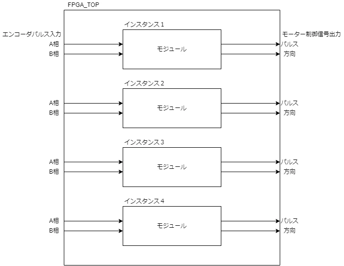
4系統のモーター制御を例にしたいと思います.
- 1つの系統における入出力
- エンコーダからの入力信号は,A相,B相が常にペア
- モータードライバへの出力は,パルス/方向が常にペア
普通に書いたVHDL
今回のお題のようなケースではstd_logic_vevtorを使って書くのも違和感があると思いますので,こんな感じにstd_logicで地道に書いたソースになるかと思います.
TOPモジュール
TOPモジュールのソースです,地道に信号を宣言しているのでモジュールインスタンスもgenerate文でループして作りづらいのでベタにインスタンスを記述しています.
library ieee;
use ieee.std_logic_1164.all;
use ieee.std_logic_arith.all;
use ieee.std_logic_unsigned.all;

entity FPGA_TOP is
	Port(
	i_ENC1_A	:in  std_logic;--1系のA相
	i_ENC1_B	:in  std_logic;--1系のB相
	i_ENC2_A	:in  std_logic;--2系のA相
	i_ENC2_B	:in  std_logic;--2系のB相
	i_ENC3_A	:in  std_logic;--3系のA相
	i_ENC3_B	:in  std_logic;--3系のB相
	i_ENC4_A	:in  std_logic;--4系のA相
	i_ENC4_B	:in  std_logic;--4系のB相

	o_MOT1_STP	:out  std_logic; --1系のパルス
	o_MOT1_DIR	:out  std_logic; --1系の方向
	o_MOT2_STP	:out  std_logic; --2系のパルス
	o_MOT2_DIR	:out  std_logic; --2系の方向
	o_MOT3_STP	:out  std_logic; --3系のパルス
	o_MOT3_DIR	:out  std_logic; --3系の方向
	o_MOT4_STP	:out  std_logic; --4系のパルス
	o_MOT4_DIR	:out  std_logic); --4系の方向
end entity;

architecture RTL of FPGA_TOP is
begin
	MC_inst1:entity work.MotorController
		port map
		(i_ENC_A	=>i_ENC1_A
		,i_ENC_B	=>i_ENC1_B
		,o_MOT_STP	=>o_MOT1_STP
		,o_MOT_DIR	=>o_MOT1_DIR
		);

	MC_inst2:entity work.MotorController
		port map
		(i_ENC_A	=>i_ENC2_A
		,i_ENC_B	=>i_ENC2_B
		,o_MOT_STP	=>o_MOT2_STP
		,o_MOT_DIR	=>o_MOT2_DIR
		);

	MC_inst3:entity work.MotorController
		port map
		(i_ENC_A	=>i_ENC3_A
		,i_ENC_B	=>i_ENC3_B
		,o_MOT_STP	=>o_MOT3_STP
		,o_MOT_DIR	=>o_MOT3_DIR
		);

	MC_inst4:entity work.MotorController
		port map
		(i_ENC_A	=>i_ENC4_A
		,i_ENC_B	=>i_ENC4_B
		,o_MOT_STP	=>o_MOT4_STP
		,o_MOT_DIR	=>o_MOT4_DIR
		);
end architecture;
サブモジュール
中の論理は省略しますので,はINとOUTを繋げて論理合成だけはできるようにしておきます.
library ieee;
use ieee.std_logic_1164.all;
use ieee.std_logic_unsigned.all;
use ieee.std_logic_arith.all;

entity MotorController is
port(
	i_ENC_A		:in	 std_logic;	--
	i_ENC_B		:in	 std_logic;	--
	o_MOT_STP	:out std_logic;	--
	o_MOT_DIR	:out std_logic);
end entity;

architecture RTL of MotorController is

begin
	o_MOT_STP <= i_ENC_A;
	o_MOT_DIR <= i_ENC_B;

end architecture;
論理合成
一応Latticeのツールで論理合成できることの確認し,合成できることを確認しました.

type宣言を使ってスッキリさせたVHDL
では,本題のtype宣言の使い方を紹介します.
ユーザー定義型の書き方
以下のようにpkgTYPEDEFというパッケージを作ります.(pkgTYPEDEFは任意の名称に変更可能です)
この中でエンコーダーパルスのA相とB相をまとめたtypEncoderという型を定義します,さらにtypEncoder型をベクターにしたtypEncoder_Vector型を定義します.
library ieee;
use ieee.std_logic_1164.all;
use	ieee.std_logic_arith.all;

package pkgTYPEDEF is
	----------------------------------------------
	--ユーザー定義型
	----------------------------------------------
	--エンコーダパルス信号
	type typEncoder is record
		A		:std_logic	;--A相
		B		:std_logic	;--B相
	end record;

	--モーター制御信号
	type typMotor is record
		STP		:std_logic	;--ステップ信号
		DIR		:std_logic	;--方向信号
	end record;

	----------------------------------------------
	-- ユーザー定義型をベクターにした型の定義
	----------------------------------------------
	type typEncoder_Vector
		is array(integer range <>) of typEncoder;

	type typMotor_Vector
		is array(integer range <>) of typMotor;

end package;
TOPモジュール
これが,ユーザー定義型を使った場合のTOPモジュールのソースです.
かなり記述行が圧縮されたと思いませんかっ!!
vectorにしているのでgenerate文も適用しやすくなります.
library ieee;
use ieee.std_logic_1164.all;
use ieee.std_logic_arith.all;
use ieee.std_logic_unsigned.all;
use work.pkgTYPEDEF.all;

entity FPGA_TOP is
	Port(
	i_ENCODER	:in  typEncoder_Vector(0 to 3);	--エンコーダ信号(A相,B相)
	o_MOTOR		:out typMotor_Vector(0 to 3)); --モーター制御信号(パルス,方向)
end entity;

architecture RTL of FPGA_TOP is
begin
	GEN_MC:for i in 0 to 3 generate
		MC_inst:entity work.MotorController
			port map
			(i_ENCODER	=>i_ENCODER(i)
			,o_MOTOR	=>o_MOTOR(i)
			);
	end generate;
end architecture;
サブモジュール
一応サブモジュール
library ieee;
use ieee.std_logic_1164.all;
use ieee.std_logic_unsigned.all;
use ieee.std_logic_arith.all;
use work.pkgTYPEDEF.all;

entity MotorController is
port(
	i_ENCODER	:in	 typEncoder;	--
	o_MOTOR	:out typMotor);
end entity;

architecture RTL of MotorController is

begin
	o_MOTOR.STP <= i_ENCODER.A;
	o_MOTOR.DIR <= i_ENCODER.B;

end architecture;
論理合成
論理合成の結果です.
ソースは短縮しましたが,等価な回路に論理合成できています!
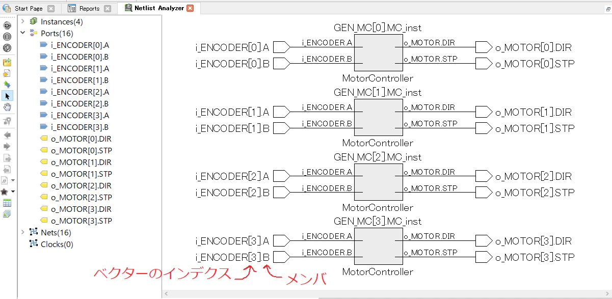
ベクターのインデックスが先に来て,ドットで区切ってユーザー定義型のメンバが続いています.
追記
Xilinxはドットがアンダーバーに変わったような,そうでなかったような・・・
細かくは覚えてませんが,今回紹介したような書き方でXilinxのデバイスも使っていたので問題なく合成できるはずです.
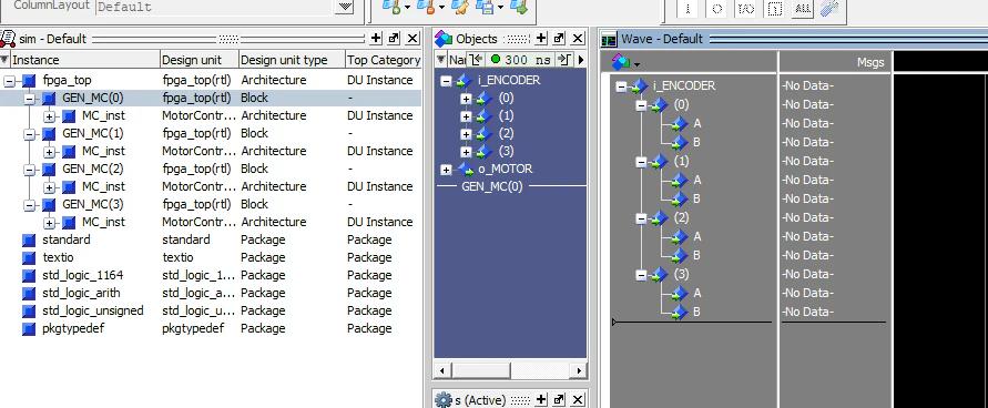
シミュレーションでは,QuestaとModelsimでは問題なく動いていました.
typeでまとめた信号はグルーピングされて折り畳み/展開が出来ますので,信号波形を並べる際にも見やすいです.
他にも,画像処理系で「データ,イネーブル,ラインスタート,ラインエンド」のように常に一緒にある信号をグルーピングしたときは,かなりスッキリとした記述ができました.