はじめに
※これはRICORA Advent Calendar 12/23 の記事になります。
本記事はカメラのキャリブレーションから始めて距離推定を行うまでの実装について説明を行います。
コードの全体は私のgithubレポジトリにあります。⇒Fisheye-Depth-Estimation
もし理論編の方を読んでいなければそちらから読むことをおススメします。前提知識がある方はこちらからでも大丈夫です。
目次
- ステレオキャリブレーション
- ステレオ平行化
- 2Dルックアップテーブル
- 正距円筒変換
- 視差推定
- 距離推定
- 実行結果
さっそくコードを見ていきましょう。クラスで書いているので少し見づらいですがご了承ください。m(__)m
1. ステレオキャリブレーション
まずはカメラのキャリブレーションからです。カメラ画像の歪みを補正するためのパラメーターを求めます。
def stereo_calibrate(self, images, image_size, board=(6,9), square_size=0.027, detail=False):
    # images -> calibrate params(left K, right K, left D, right D)
    self._image_size = image_size[::-1]
    self._board = board
    self._square_size = square_size
    print(f"Board type: rows{board[0]}, cols{board[1]}")
    assert isinstance(images, list), "images must be list"
    # Corners detection
    print("detecting corners ...")
    left_corners = []
    right_corners = []
    object_point = self._create_object_point()
    object_points = []
    for image in tqdm(images):
        left_corner, right_corner = self._detect_corners(image)
        # All corners must be detected. n_corners = (rows * cols)
        assert len(left_corner)==len(right_corner)==board[0]*board[1], "Corners detection failed."
        left_corners.append(left_corner.reshape(1,-1,2))
        right_corners.append(right_corner.reshape(1,-1,2))
        object_points.append(object_point)
    print("corners detection was successful.")
    print("stereo calibrating ...")
    self._rvec = [np.zeros((1, 1, 3), dtype=np.float64) for i in range(len(images))]
    self._tvec = [np.zeros((1, 1, 3), dtype=np.float64) for i in range(len(images))]
    self._ret, self._left_K, self._left_D, self._right_K, self._right_D, self._rvec, self._tvec = cv2.fisheye.stereoCalibrate(
        objectPoints=object_points,
        imagePoints1=left_corners,
        imagePoints2=right_corners,
        K1=self._left_K,
        D1=self._left_D,
        K2=self._right_K,
        D2=self._right_D,
        imageSize=self._image_size,
        flags=cv2.fisheye.CALIB_RECOMPUTE_EXTRINSIC
    )
    print("stereo calibration was successful.")
    if detail:
        self.show_stereo_params()
    stereo_params_dict = {
        "left_K": self._left_K,
        "right_K": self._right_K,
        "left_D": self._left_D,
        "right_D": self._right_D,
        "rvec": self._rvec,
        "tvec": self._tvec
    }
    return stereo_params_dict
imagesにはチェッカーボードの映った画像を20枚ほど渡します。image_sizeには(2560,960)のように画像サイズを渡します。boardはチェッカーボードの形状(h,w)です。square_sizeはマス目の一辺の長さ(メートル)です。
object_pointは各コーナーが左上を(0,0)としてどの座標にあるかをメートル単位で保持している配列です。
まずは各チェッカボード画像のコーナー検出を行っていきます。その作業を行っている関数が_detect_cornersです↓
def _create_object_point(self):
    # _ -> object points grid refered board
    object_point = np.zeros((1, self._board[0]*self._board[1], 3), np.float32)
    object_point[0,:,:2] = np.mgrid[0:self._board[0], 0:self._board[1]].T.reshape(-1, 2)
    object_point = object_point*self._square_size
    return object_point

def _detect_corners(self, image):
    # image -> left half corners point, right corners point
    left_image, right_image = self._split_image(image)
    flag = cv2.CALIB_CB_ADAPTIVE_THRESH+cv2.CALIB_CB_FAST_CHECK+cv2.CALIB_CB_NORMALIZE_IMAGE
    criteria = (cv2.TERM_CRITERIA_EPS | cv2.TERM_CRITERIA_MAX_ITER, 30, 0.001)
    left_ret, left_corner = cv2.findChessboardCorners(left_image, self._board, flag)
    if len(left_corner)>0:
        for points in left_corner:
            cv2.cornerSubPix(left_image, points, winSize=(3, 3), zeroZone=(-1,-1), criteria=criteria)
    right_ret, right_corner = cv2.findChessboardCorners(right_image, self._board, flag)
    if len(right_corner)>0:
        for points in right_corner:
            cv2.cornerSubPix(right_image, points, winSize=(3, 3), zeroZone=(-1,-1), criteria=criteria)
    return left_corner, right_corner
OpenCVのfindChessboardCorners関数を使うことでコーナーを検出しています。さらに検出したコーナー座標(整数)をcornerSubPixという関数で小数点まで求めます。これをサブピクセル処理と言います。
後は求まったコーナー座標をfisheye.stereoCalibrateに渡すと補正に必要なパラメーターが求まります。
ここでKはカメラマトリックス、Dは歪み係数ベクトルです。
K =
\begin{pmatrix}
f_x & 0 & c_x \\
0 & f_y & c_y \\
0 & 0 & 1
\end{pmatrix}
\qquad
D = (k_1,k_2,k_3,k_4)
ここでfは焦点距離cは中心座標を表しています。OpenCVにはこのパラメーターを使って画像を補正してくれる関数が存在しますがここでは使いません。補正に関する式なども含めて詳しくはOpenCV公式リファレンスを参照してください。
2.ステレオ平行化
def stereo_rectify(self, detail=False):
    # _ -> rectify params(left R, right R, left P, right R, Q)
    print("stereo rectify...")
    flags = cv2.fisheye.CALIB_RECOMPUTE_EXTRINSIC
    self._left_R, self._right_R, self._left_P, self._right_P, self._Q = cv2.fisheye.stereoRectify(
        K1=self._left_K,
        D1=self._left_D,
        K2=self._right_K,
        D2=self._right_D,
        imageSize=self._image_size,
        R=self._rvec,
        tvec=self._tvec,
        flags=cv2.fisheye.CALIB_RECOMPUTE_EXTRINSIC,
        newImageSize=(int(self._image_size[0]*self._mag), int(self._image_size[1]*self._mag)),
        fov_scale=self._mag
    )
    print("stereo rectification was successful.")
    if detail:
        self.show_rectify_params()
    rectify_params_dict = {
        "left_R": self._left_R,
        "right_R": self._right_R,
        "left_P": self._left_P,
        "right_P": self._right_P,
        "Q": self._Q
    }
    return rectify_params_dict
先ほどと違ってこちらの操作は非常にシンプルです。ステレオキャリブレーションで求めたパラメーターをfisheye.stereoRectify関数に渡すだけです。説明をしていませんでしたがRとtvecはそれぞれカメラ間の変換を行うための行列とベクトルですステレオキャリブレーションの際に求まります。
fov_scaleについてですが、これはどれぐらい広く画角を取るかを決めるための値です。(fov=Field of view)
今回はここに2を渡して2倍の画角で平行化画像を取得します。
この関数によって平行化変換の回転行列R(33)と平行座標系に投影を行うための行列P(34)が求まります。これらを使って平行化画像を生成することができます。
3. 2Dルックアップテーブル
理論編で登場していない単語が出てきました。2Dルックアップテーブルについて解説します。
2Dルックアップテーブルとは計算を高速化するためのマッピング行列です。マッピングとは点と点を結びつけることです。
先ほど求めたパラメーターからそれぞれの画素がどの座標に移動するかを計算しておいて、それを適用することで素早く画像の変換を行うことができます。
パラメーターを使って変換をしようとすると、各画素に対して毎回行列の計算を行う必要があり時間がかかってしまいます。
def create_rectify_map(self):
    # _ -> rectify maps(left x, left y, right x, right y)
    self._left_rectify_map_x, self._left_rectify_map_y = cv2.fisheye.initUndistortRectifyMap(
        K=self._left_K,
        D=self._left_D,
        R=self._left_R,
        P=self._left_P,
        size=(int(self._image_size[0]*self._mag), int(self._image_size[1]*self._mag)),
        # size=self._image_size,
        m1type=cv2.CV_32FC1
    )
    self._right_rectify_map_x, self._right_rectify_map_y = cv2.fisheye.initUndistortRectifyMap(
        K=self._right_K,
        D=self._right_D,
        R=self._right_R,
        P=self._right_P,
        size=(int(self._image_size[0]*self._mag), int(self._image_size[1]*self._mag)),
        # size=self._image_size,
        m1type=cv2.CV_32FC1
    )
    print("rectify lookup table ceraeted.")
    rectify_map_dict = {
        "left_map_x": self._left_rectify_map_x,
        "left_map_y": self._left_rectify_map_y,
        "right_map_x": self._right_rectify_map_x,
        "right_map_y": self._right_rectify_map_y
    }
    return rectify_map_dict
fisheye.initUndisortedRectifyMapという関数にこれまで求めたパラメーターK,D,R,Pを渡してx座標のマップ、y座標のマップをそれぞれ取得することができます。
このマッピングはインデックス番号と要素が直感的に逆になっていることに注意してください。どういうことかというと、元画像の座標を(x , y)、平行化画像の座標を(i , j)としたときに
map_x[j][i] = x,
\qquad
map_y[j][i] = y
となっています。つまり平行化画像⇒元画像というような座標変換です。このようにすることで変換先の座標に対してより高速かつ正確にマッピングを行うことができます。
このマップにremap関数を使うと画像変換を行うことができます。
4. 正距円筒変換
次に正距円筒変換です。これはOpenCVに関数が無いので自分で直接2Dルックアップテーブルを作成します。具体的には平行化画像から正距円筒画像に変換するマッピングを計算します。特に上で説明したインデックス番号と要素の関係に注意します。
def create_equirectangular_map(self, axis="vertical", mag_x=1.0, mag_y=1.0):
    # _ -> eqrec maps(left x, left y, right x, right y)
    assert axis in ["horizontal", "vertical"], "Select horizontal or vertical as axis."
    w,h = self._image_size
    w = int(w * mag_x)
    h = int(h * mag_y)
    self._left_eqrec_map_x = np.zeros((h,w), dtype=np.float32)
    self._left_eqrec_map_y = np.zeros((h,w), dtype=np.float32)
    self._right_eqrec_map_x = np.zeros((h,w), dtype=np.float32)
    self._right_eqrec_map_y = np.zeros((h,w), dtype=np.float32)
    # left map
    fx = self._left_P[0,0]
    fy = self._left_P[1,1]
    cx = self._left_P[0,2]
    cy = self._left_P[1,2]
    for y in range(h):
        for x in range(w):
            if axis=="vertical":
                lamb = (1.0 - y/(h/2.0)) * (math.pi/2.0)
                phi = (x/(w/2.0) - 1.0) * (math.pi/2.0)
                vs_y = math.tan(lamb)
                vs_x = math.tan(phi) / math.cos(lamb)
                rec_x = cx + vs_x*fx
                rec_y = cy - vs_y*fy
                self._left_eqrec_map_x[y,x] = rec_x
                self._left_eqrec_map_y[y,x] = rec_y
            elif axis=="horizontal":
                lamb = (1.0 - x/(w/2.0)) * (math.pi/2.0)
                phi = (1.0 + y/(h/2.0)) * (math.pi/2.0)
                vs_x = math.tan(lamb)
                vs_y = math.tan(phi) / math.cos(lamb)
                rec_x = cx - vs_x*fx
                rec_y = cy + vs_y*fy
                self._left_eqrec_map_x[y,x] = rec_x
                self._left_eqrec_map_y[y,x] = rec_y
    # right map
    fx = self._right_P[0,0]
    fy = self._right_P[1,1]
    cx = self._right_P[0,2]
    cy = self._right_P[1,2]
    for y in range(h):
        for x in range(w):
            if axis=="vertical":
                lamb = (1.0 - y/(h/2.0)) * (math.pi/2.0)
                phi = (x/(w/2.0) - 1.0) * (math.pi/2.0)
                vs_y = math.tan(lamb)
                vs_x = math.tan(phi) / math.cos(lamb)
                rec_x = cx + vs_x*fx
                rec_y = cy - vs_y*fy
                self._right_eqrec_map_x[y,x] = rec_x
                self._right_eqrec_map_y[y,x] = rec_y
            elif axis=="horizontal":
                lamb = (1.0 - x/(w/2.0)) * (math.pi/2.0)
                phi = (1.0 + y/(h/2.0)) * (math.pi/2.0)
                vs_x = math.tan(lamb)
                vs_y = math.tan(phi) / math.cos(lamb)
                rec_x = cx - vs_x*fx
                rec_y = cy + vs_y*fy
                self._right_eqrec_map_x[y,x] = rec_x
                self._right_eqrec_map_y[y,x] = rec_y
    print("equirectangular lookup table ceraeted.")
    eqrec_map_dict = {
        "left_map_x": self._left_eqrec_map_x,
        "left_map_y": self._left_eqrec_map_y,
        "right_map_x": self._right_eqrec_map_x,
        "right_map_y": self._right_eqrec_map_y
    }
    return eqrec_map_dict
正距円筒画像にすると少し画像が縦につぶれ気味になってしまっていたので、マッチングがしやすくなるように縦横の大きさを定数倍できるようになっています。またエピポーラ線がどの方向に歪む変換を行うかのオプションも用意してあります。今回は縦方向のエピポーラ線が変化する変換なのでverticalです。計算式を以下に示します。
\lambda = (1 - \frac{y}{h/2})\frac{\pi}{2},
\quad
\phi = (\frac{x}{w/2} - 1)\frac{\pi}{2} \qquad (正距円筒の座標系)
vs_y = \tan{\lambda},
\quad
vs_x = \frac{\tan{\phi}}{\cos{\lambda}} \qquad (z=1スクリーン上での座標)
rec_y = c_y - vs_y * f_y
\quad
rec_x = c_x + vs_x * f_x \qquad (ピクセル座標)
緯度経度といいう意味でλ, Φという記号を使っています。rec_x, rec_yが平行化画像の座標です。
マッピングの事情で正距円筒画像⇒平行化画像という順番で計算を行っています。もし逆の計算を行うとどうなるでしょうか?
一応座標は求まるのでマッピングを計算することはできます。しかし、インデックス番号は整数でなくてはならないので必然的に正距円筒画像の座標をintに丸めることになります。こうなってしまうと画像の一部が欠けるようなマッピングができてしまいます。なので正距円筒画像⇒平行化画像の順で計算を行う必要があります。
5. 視差推定
画像の変換が完了したのでマッチングを適用して視差を求めましょう。
def stereo_matching(self, save=None, show=True):
    # image -> disparity map
    assert self._image is not None, "Plz set image first."
    print("stereo matching ...")
    stereo = cv2.StereoSGBM_create(
        numDisparities = self._num_disparities,
        blockSize = self._window_size,
        P1 = 8 * 3 * self._window_size**2,
        P2 = 32 * 3 * self._window_size**2,
        disp12MaxDiff = 1,
        uniquenessRatio = 10,
        speckleWindowSize = 150,
        speckleRange = 32,
        mode=cv2.StereoSGBM_MODE_HH
    )
    blur = 7
    self._left_image = cv2.GaussianBlur(self._left_image,(blur,blur),blur)
    self._right_image = cv2.GaussianBlur(self._right_image,(blur,blur),blur)
    self._disparity_map = stereo.compute(self._left_image, self._right_image).astype(np.float32)
    self._disparity_map = self._disparity_map / 16.0
    if save:
        fig = plt.figure(figsize=(15,15))
        plt.imshow(self._disparity_map)
        plt.axis("off")
        fig.savefig(save)
    if show:
        self._show_images(images=[cv2.cvtColor(self._image, cv2.COLOR_BGR2RGB), self._disparity_map], titles=["Original", "Disparity"], figsize=(30,20), subplot=(1,2))
    return self._disparity_map
OpenCVのStereoSGBMというクラスを使います。numDisparitiesに計算を行う視差の最大値を、blockSizeに探索ウィンドの大きさを、P1,P2には動的計画法で使用するペナルティーをそれぞれ渡します。今回は最大視差100、ウィンドサイズ7で実行しています。
この値を変えることで画像の遠くと近くのどっちを正確に計算するか調整することができます。P1,P2については公式ドキュメントに記載してある式をそのまま使っています。
計算を行う前に画像に軽いぼかしを入れておくとマッチングがきれいに計算されやすいです。
最後に視差を16で割っていることに気を付けてください。理由はよくわかりませんがOpenCVの仕様で求めたい値の16倍になっているそうです。(4bit分左にずれていると考えられる)
6. 距離推定
ようやくここまで来ました。あとは視差画像から距離を計算するだけです。
def depth_estimation(self, axis="vertical",threshold=(0.0,2.0), save=None, show=True):
assert self._disparity_map is not None, "Plz run stereo matching first."
height = self._left_image.shape[0]
width = self._left_image.shape[1]
self._depth_map = np.zeros(self._disparity_map.shape , np.float32)
if axis == "vertical":
for y in range(height):
for x in range(width):
lamb = (1.0 - y/(height/2.0)) * (math.pi/2.0)
phi = (x/(width/2.0) - 1.0) * (math.pi/2.0)
delta_phi = self._disparity_map[y,x] / (width/2.0) * (math.pi/2.0)
distance = self._baseline * math.sin(math.pi/2.0 - phi) / (1e-7+math.sin(delta_phi) * math.cos(lamb))
self._depth_map[y,x] = distance *math.cos(phi) * math.cos(lamb)
elif axis == "horizontal":
for y in range(height):
for x in range(width):
lamb = (1.0 + y/(height/2.0)) * (math.pi/2.0)
phi = (1.0 - x/(width/2.0)) * (math.pi/2.0)
delta_lamb = -(self._disparity_map[y,x] / (width/2.0)) * (math.pi/2.0)
distance = self._baseline * math.sin(math.pi/2.0 - lamb) / (1e-7+math.sin(delta_lamb) * math.cos(phi))
self._depth_map[y,x] = distance * math.cos(phi)
self._depth_map = np.where((self._depth_map < threshold[0]) | (self._depth_map > threshold[1]), 0.0, self._depth_map)
if save:
fig = plt.figure(figsize=(15,15))
plt.imshow(self._depth_map)
plt.axis("off")
fig.savefig(save)
if show:
self._show_images(images=[cv2.cvtColor(self._image, cv2.COLOR_BGR2RGB), self._depth_map], titles=["Original", "Depth"], figsize=(30,20), subplot=(1,2),color_bar=True)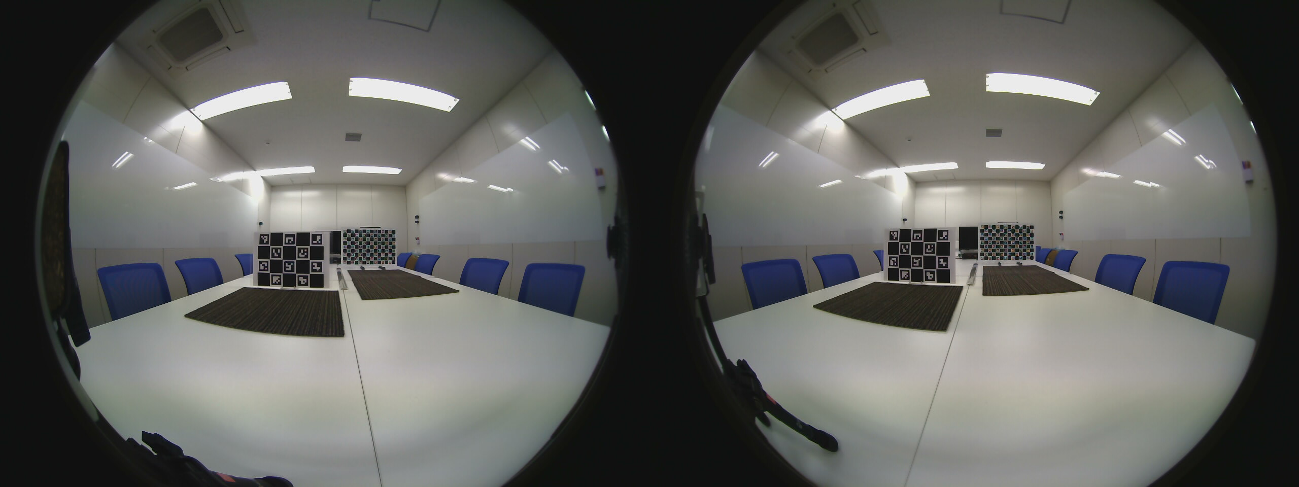
return self._depth_map
こちらもverticalとして計算を行います。式はシンプルに見えて意外と複雑です。視差をdとしています↓
\lambda = (1 - \frac{y}{h/2})\frac{\pi}{2},
\quad
\phi = (\frac{x}{w/2} - 1)\frac{\pi}{2} \qquad (正距円筒の座標系)
\Delta\phi = \frac{d_{x,y}}{w/2}\frac{\pi}{2} \qquad (視差を角度に変換)
\qquad\qquad distance = \frac{B\sin{(\frac{\pi}{2} - \phi)}}{\epsilon + \sin{(\Delta\phi)}\cos{(\lambda)}} \qquad (カメラからの距離を計算,\epsilon=10^{-7})
depth_{x,y} = distance * \cos{\phi} * cos{\lambda} \qquad (奥行きを計算)
カメラからの距離と奥行きは異なることに注意してください。今回求めたい距離というのは奥行きのことなのでカメラとの距離にcosを掛けています。
7. 実行結果
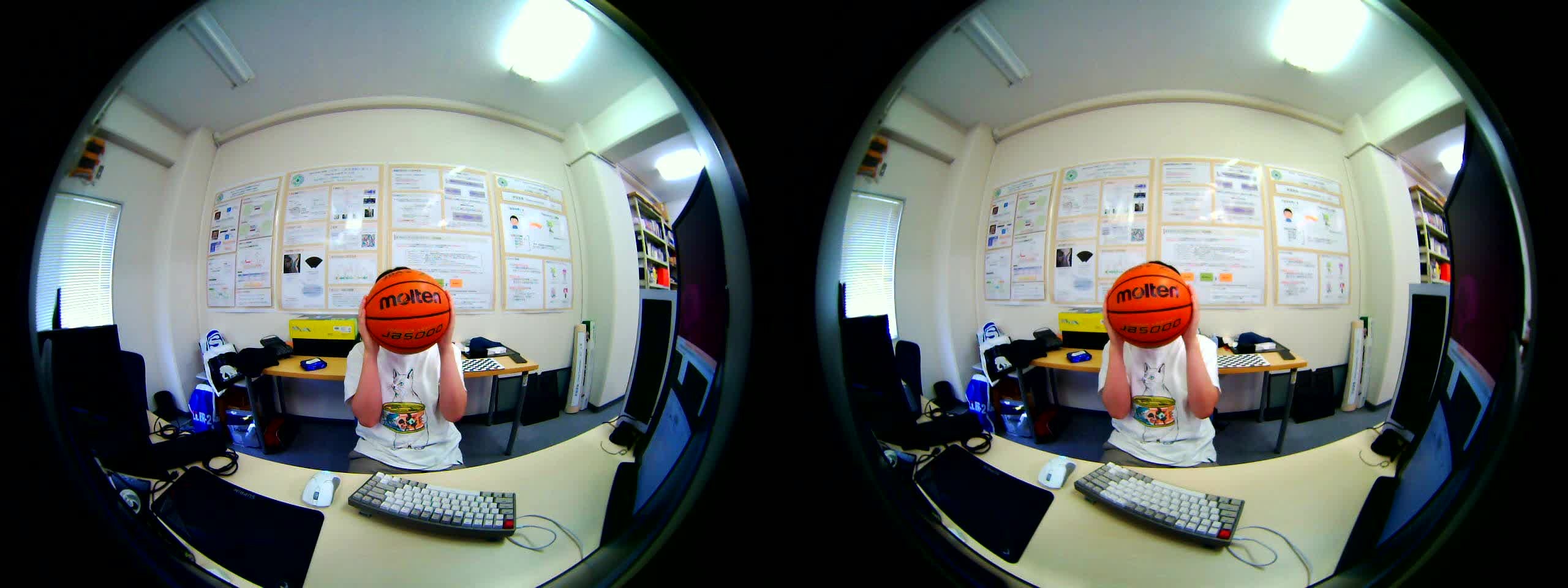
実際に撮影した画像を使って実験をしてみたいと思います!
今回実験に使う画像です。私がバスケットボールを持っています。
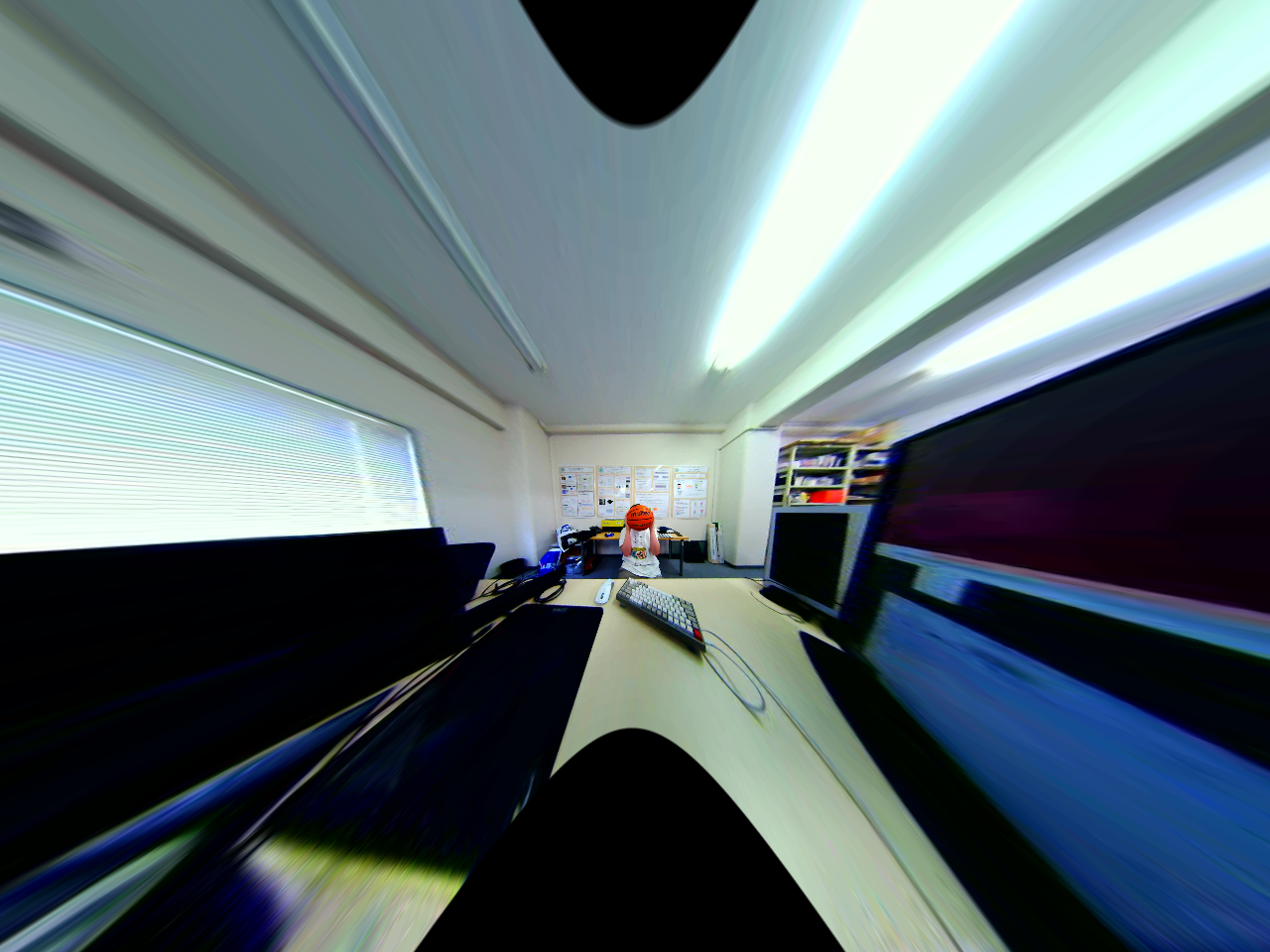
まずは平行化変換です。画角が十分に得られている反面、端が相当引き伸ばされてしまっています。
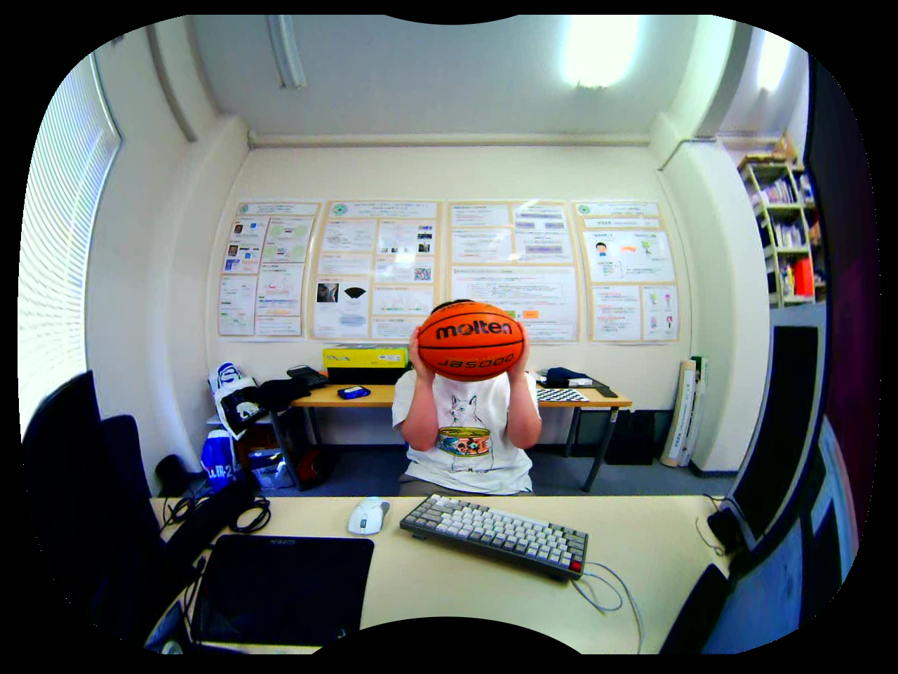
次に正距円筒変換です。平行化画像のエピポーラ線を保ったまま引き延ばしを解消できていることが分かると思います!
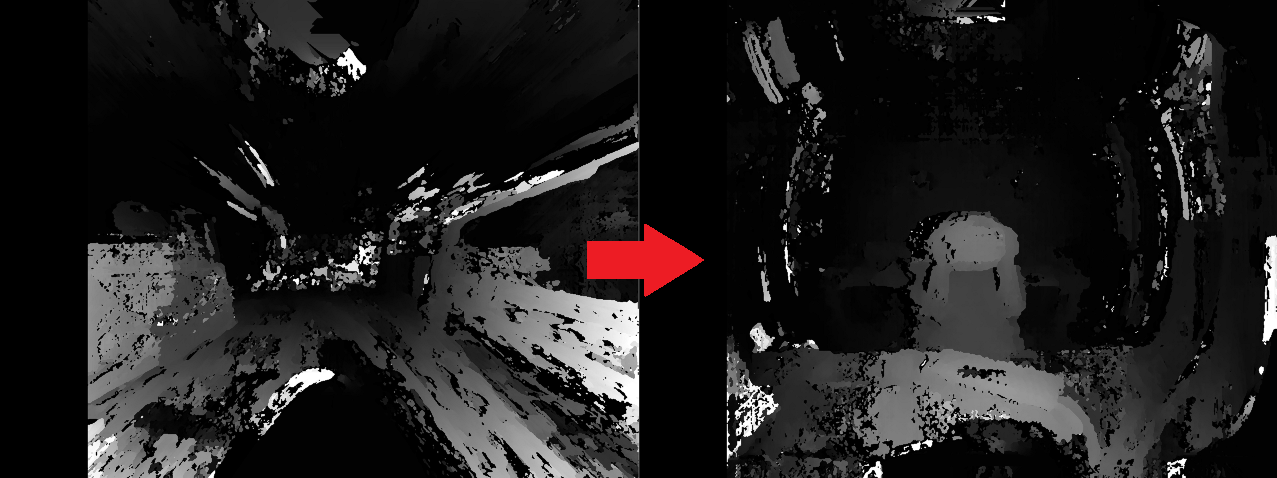
そして視差推定です。左が平行化画像での結果、右が正距円筒画像の結果です。正距円筒画像の方が視差がはっきりととれているのが分かります。マッチングアルゴリズムはテクスチャの無いものを正しく推定するのが困難なので、テーブルが汚くなっているのは大目に見てください。思いのほかキーボードやマウスもきれいにとれてそうです。
最後は距離推定です。距離化した画像はRGB画像と合わせることで3次元空間の点群を構成することができます。CloudCompareというツールを使うと3次元点群を描画することができます。
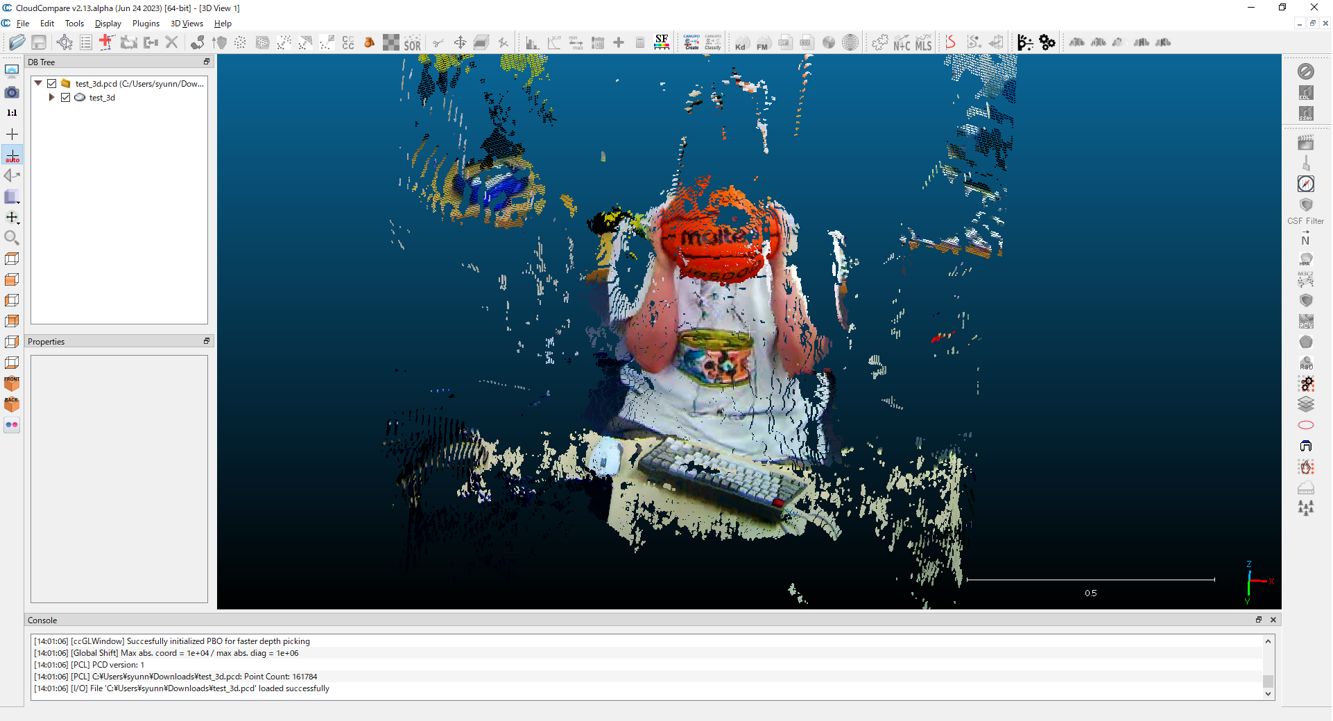
この再構成された点群から精度よく距離を計測できていることが確認できます!かなり高精度と言えるでしょう。
まとめ
ここまで読んでいただき、ありがとうございました!
理論編と実装編の2つに分けて魚眼ステレオカメラによる距離推定を解説しました。記事の投稿は初なので読みずらいところなどがあったら指摘していただけると幸いです。
GitHubの実装も見ていただけると嬉しいです。
この技術の応用先として、例えば車やロボットに搭載するというタスクが最近増えています。こここでは誤差が数cmだったのとテクスチャが無いと計測が困難という点で実践に耐えうる性能は出せませんでした。
現場ではディープラーニングを使ってより高精度な計測を行えるモデルの開発が行われています。距離推定の今後に期待です!