ピエゾ振動センサーを使う その2
概要
の続き。実際にセンシングして、I2Cで別のArduinoにデータを飛ばす
Seeeduino V4のsketch
#include <Wire.h>

#define SLAVE_ADDRESS 0x08

const int ledPin=13;
int high_count=0;

void setup() {
    Wire.begin();
    Serial.begin(9600);
    pinMode(ledPin,OUTPUT);
}

void loop() {
    int sensorState = digitalRead(2);
    delay(100);
    if(sensorState == HIGH)
    {
        high_count++;
        if(high_count>10){
            Serial.println("send");
            Wire.beginTransmission(SLAVE_ADDRESS);
            Wire.write("HELP ME!");
            Wire.endTransmission(SLAVE_ADDRESS);
        }
        digitalWrite(ledPin,HIGH);
    }
    else
    {
        digitalWrite(ledPin,LOW);
        high_count=0;
    }
}
APIはここを見る
ピエゾセンサはGroveのベースシールドHATのD2なので、digitalRead(2)で読む。
読めるのはHIGH(1)とLOW(0)になる。
HIGHを検知している間はdigitalWrite()で13PinのLEDを点灯させる。
Seeeduinoの場合は青色が光る。
だいたい100ミリ周期で10回HIGHを検知したら、I2Cで「HELP ME!」を送る。
送り方は
Wireを使って、スレーブである0x08に対してbeginTransmission()で送信して、endTransmission()で終わる
Arduino Uno R4 wifiのsketch
#include <Wire.h>
#include "Arduino_LED_Matrix.h"   // Include the LED_Matrix library
#include "frames.h"               // Include a header file containing some custom icons

#define SLAVE_ADDRESS 0x08

volatile bool newData = false;
char receivebuffer[32];
ArduinoLEDMatrix matrix;          // Create an instance of the ArduinoLEDMatrix class

void setup() {
  Wire.begin(SLAVE_ADDRESS);                // join I2C bus with address #8
  Wire.onReceive(receiveEvent); // register event
  Serial.begin(9600);           // start serial for output
  matrix.begin();
  pinMode(LED_BUILTIN, OUTPUT);
}

void loop() {
  //Serial.println("on");
  digitalWrite(LED_BUILTIN, (millis() / 500) % 2 );
  matrix.loadFrame(chip);
  delay(500);  // Pause for 500 milliseconds (half a second)

  matrix.loadFrame(LEDMATRIX_HEART_BIG);
  delay(500);

  if (newData){
    Serial.print("Recieved: ");
    Serial.println(receivebuffer);
    matrix.loadFrame(danger);
    delay(3000);
    newData = false;
  }
  matrix.clear();
  delay(1000);
}
includeしているframe.hはローカルで以下を作る
const uint32_t chip[] = {
	0x1503f811,
	0x3181103,
	0xf8150000
};

const uint32_t danger[] = {
	0x400a015,
	0x1502082,
	0x484047fc
};

const uint32_t happy[] = {
	0x19819,
	0x80000001,
	0x81f8000
};

const uint32_t heart[] = {
	0x3184a444,
	0x44042081,
	0x100a0040
};
こうすると、マスタ側から送られたI2Cをトリガにして、割り込みが発生してフラグをたてる。
loopに戻って、割り込みがあればシリアルとLEDの処理を行う。
wifiでJsonを送信
でwifiでのJson送信のサンプルを作った。
無事JsonをHTTPサーバへ送ることができた。
HTTPサーバは
を使った。
困ったこと1 I2Cのスレーブが見つからない!!
SeeeduinoのI2CのGroveポートは4つあり、内部ですべて同じ回路につながっている。
ので、I2CのGroveポートはどこを使っても、接続先のSlaveのアドレスで認識できる。
が、どんなに頑張ってもArduino Uno R4 Wifiが見つからないので、HELP ME!が届かない。
i2cscannerで相手を探す
Seeeduinoに以下のsketchを書いて、スレーブが見つかるかを確認する
#include <Wire.h>

void setup()
{
    Wire.begin();
    Serial.begin(9600);
    Serial.println("\nI2C Scanner");
}

void loop()
{
    byte error, address;
    int nDevices;

    Serial.println("Scanning...");

    nDevices = 0;
    for (address = 1; address < 127; address++ )
    {
        Wire.beginTransmission(address);
        error = Wire.endTransmission();

        if (error == 0)
        {
            Serial.print("I2C device found at address 0x");
            if (address < 16)
                Serial.print("0");
            Serial.print(address, HEX);
            Serial.println("  !");

            nDevices++;
        }
        else if (error == 4)
        {
            Serial.print("Unknown error at address 0x");
            if (address < 16)
                Serial.print("0");
            Serial.println(address, HEX);
        }
    }
    if (nDevices == 0)
        Serial.println("No I2C devices found\n");
    else
        Serial.println("done\n");

    delay(5000);           // wait 5 seconds for next scan
}
この結果は
「No I2C devices found」
だったので、やはりi2cの相手が見えていなかった。
そこで、次のデバッグへ。
デバッグ2 結線を変える。
最初は[Seeeduino]-(GROVE)----(qwiic)-[Arduino Uno]で行けるだろうと思って、
を買ってみた。
が、I2Cの規格はシリアルデータ (SDA) とシリアルクロック (SCL) とVCC、GNDであり、Grove-qwiicでボードをつないでしまうと、その4本が直結する。
つまり、お互いのVCCで給電がぶつかるので、電流の回り込みが起きてしまう。
これは良くないので、接続を見直し。
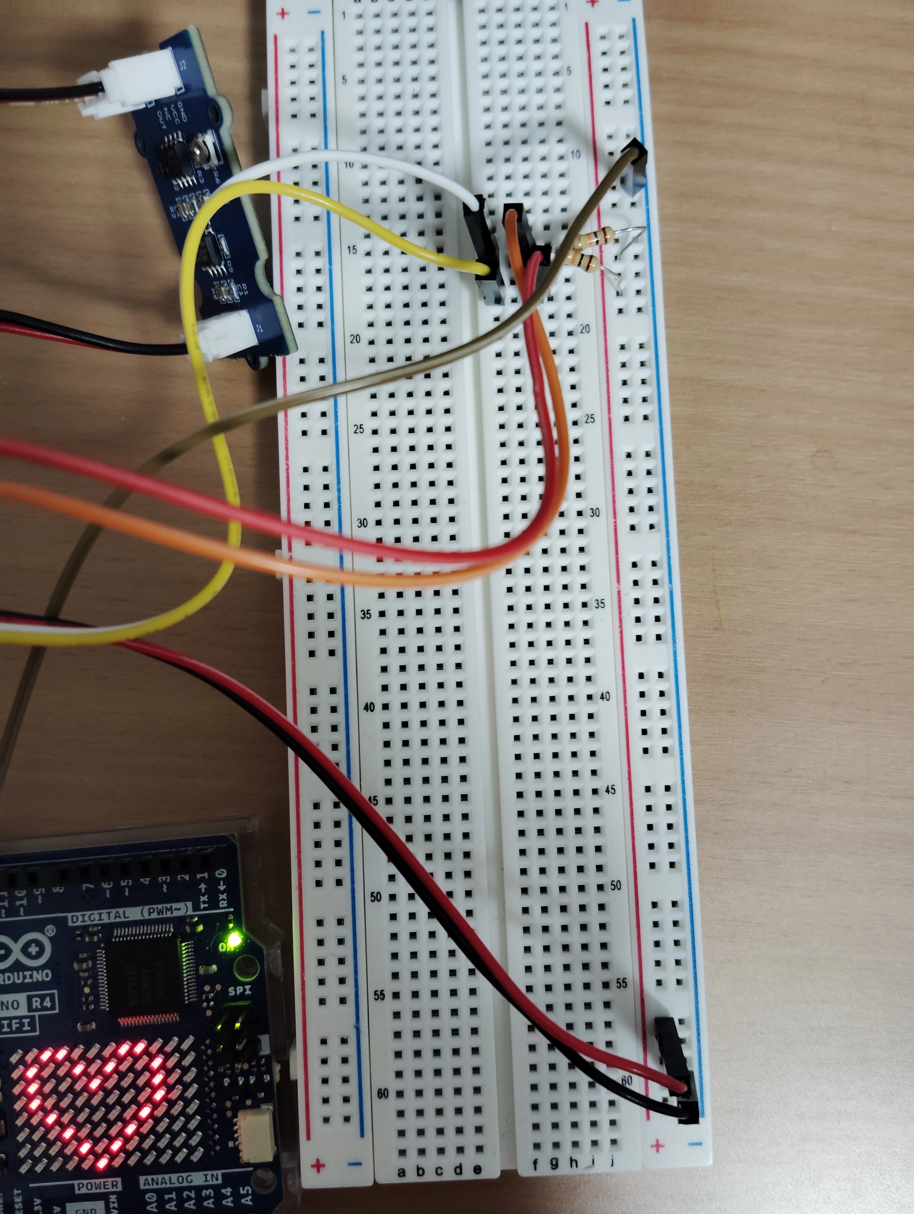
分かりにくいけど、2つのボードのGNDをブレットボードの右のマイナスのラインに接続
SeeeduinoのVCCをブレットボードのプラスに接続
2つのボードのSDAとSCLを同じ列(ブレットボードの数字が同じ)に配置して、その列からプラスへ10Kオームの抵抗を配置(プルアップ抵抗)して、スイッチOFF時などの入力端子の電位を「High(高レベル)」に固定する
SeeeduinoとBase ShieldのVCCのスライドスイッチ設定はともに3.3Vにしておく。
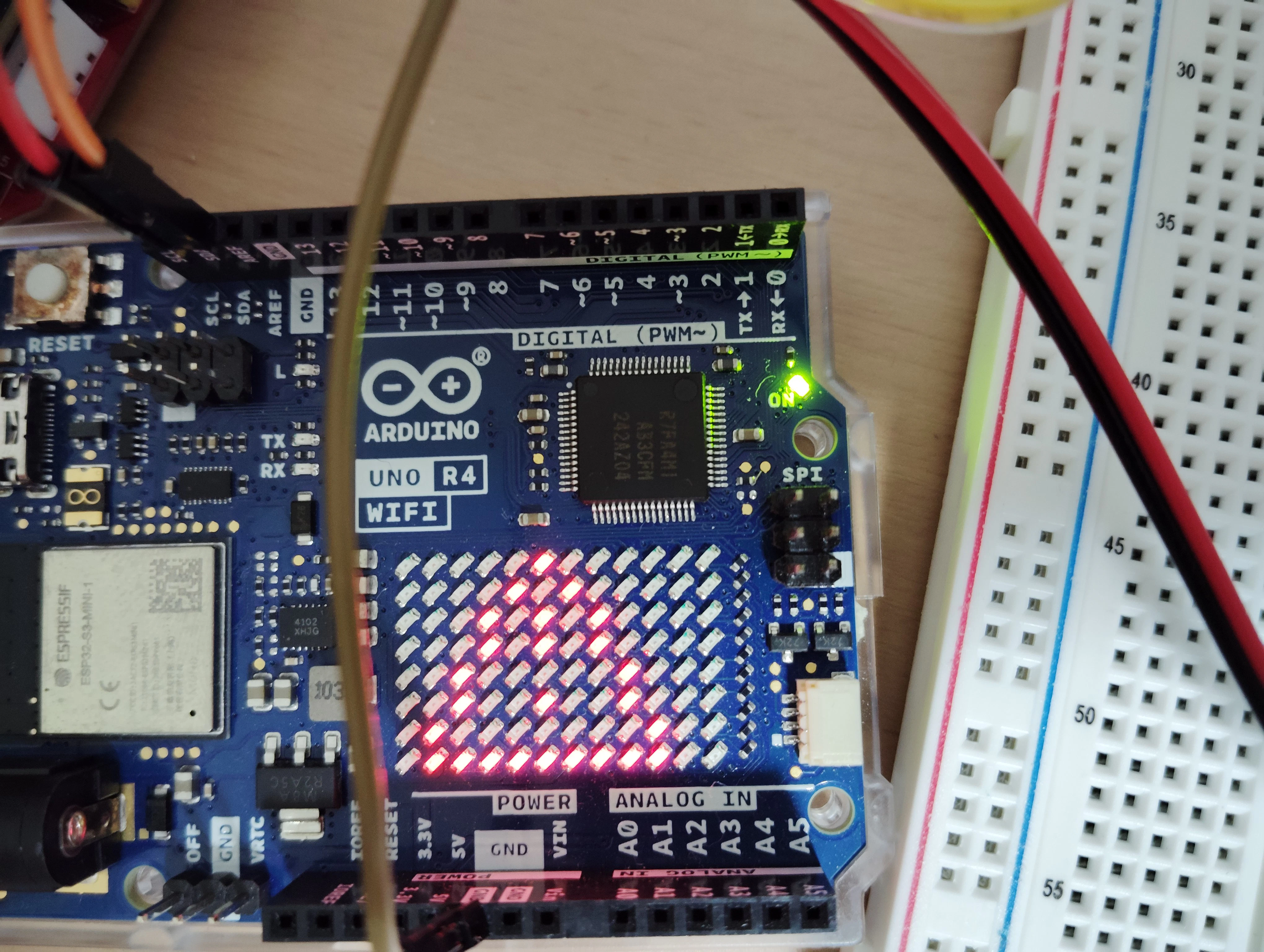
接続が終わったら、両方のボードをスレーブ→マスターの順に電源入れる。
今回は9V1AでセンタープラスのACアダプタを2つ用意した。
SeeeduinoからのI2Cを受けて、無事DangerのLEDが点灯した。
困ったこと2 i2cが途中で止まる。
i2cの通信ができるようになってすぐにハマったのが、「HELP ME!」と送るとスレーブ側のシリアルが「H」だけしか出ない。さらにマスタ、スレーブともにハングする。
Geminiを使って原因を探っていくと、割り込みハンドラ内でSerial.printlnをしていたのが原因だった。
なので、割り込み内の処理をフラグだけにして、loop()側にSerial.printlnを持っていくと、意図通り動いた。
割り込み内では重たい処理はだめ。