はじめに
mozziのサンプル見てたら、inputができそうなので、せっかくだったら
エフェクター(フィードバックディレイ・ローパスフィルター)をつけたミキサーを作ってみようかと・・
mozziの設定
inputを使うには、/root/Arduino/Mozzi-1.0.3rc4/libraries/mozzi_config.hに2行ほど追加する必要があります。(inputのサンプルスケッチにも書いてあります)
※mozzi_config.hの場所は環境によって違うと思います※
#define AUDIO_INPUT_PIN 0
#define USE_AUDIO_INPUT true
これで、アナログPINの0(A0)をインプットとして使えます。
パーツリスト
■AMAZONで購入
arduino UNO R3(の互換品)
3.5mmステレオジャック
LED
抵抗
■共立エレショップ(通販)
ボリューム(10KΩ Bカーブ)(http://eleshop.jp/shop/g/gE52362/)
■aitendo(通販)
つまみ(http://www.aitendo.com/product/12732)
■秋月電子で購入(通販)
秋月バニラシールド(http://akizukidenshi.com/catalog/g/gP-09624/)
スケッチ
/*  Test of audio and control rate analog input using Mozzi sonification library.

  An audio input using the range between 0 to 5V on analog pin A0
  is sampled and output on digital pin 9.
  All the other analog channels are sampled at control rate and printed to Serial.

  Demonstrates mozziAnalogRead(pin), which reads analog inputs in the background,
  and getAudioInput(), which samples audio on AUDIO_INPUT_PIN, configured in mozzi_config.h.

  Configuration: requires these lines in the Mozzi/mozzi_config.h file:
  #define USE_AUDIO_INPUT true
  #define AUDIO_INPUT_PIN 0


  Circuit:
  Audio cable centre wire on pin A0, outer shielding to Arduino Ground.
  Audio output on DAC/A14 on Teensy 3.0, 3.1, or digital pin 9 on a Uno or similar, or
  check the README or http://sensorium.github.com/Mozzi/
  Analog sensor inputs on any other analog input pins.
  The serial printing might cause glitches, so try commenting
  them out to test if this is a problem.

  Mozzi help/discussion/announcements:
  https://groups.google.com/forum/#!forum/mozzi-users

  Tim Barrass 2013, CC by-nc-sa.
*/

# include <MozziGuts.h>
# include <Oscil.h>
# include <AudioDelayFeedback.h>
# include <EventDelay.h>
# include <LowPassFilter.h>

LowPassFilter lpf;

AudioDelayFeedback <256, ALLPASS> aDel;

EventDelay kDelay;

byte LPF_F;
int FL;
float DT;


void setup() {
  Serial.begin(115200);
  pinMode(8,OUTPUT);
  lpf.setResonance(220);
  startMozzi();

}


void updateControl(){
  if(kDelay.ready()){
    int lpf_f=mozziAnalogRead(3);
    LPF_F=map(lpf_f,0,1023,255,0);
    lpf.setCutoffFreq(LPF_F);
    Serial.print("");
    Serial.print("\t"); // tab
    int dt=mozziAnalogRead(2);
    DT=map(dt,0,1023,6400,800);
    aDel.setDelayTimeCells(DT); // Allpass interpolation for fractional delay time
    Serial.print(DT);
    Serial.print("\t"); // tab
    int fl=mozziAnalogRead(1);
    FL=map(fl,0,1023,120,-120);
    aDel.setFeedbackLevel(FL);
    Serial.print(FL);
    Serial.println("\t"); // tab
    kDelay.start(300);
  }
}

int updateAudio(){
  int asig = getAudioInput(); // range 0-1023
  asig = asig - 512; // now range is -512 to 511
  if (LPF_F<5){
    digitalWrite(8,LOW);
    asig >>=2;
  }
  else{
    digitalWrite(8,HIGH);
    asig >>= 4; // now it's -128 to 127, within audio output range
    asig=aDel.next(asig);
    asig=lpf.next(asig);
  }
  return asig;
}


void loop(){
  audioHook();
}
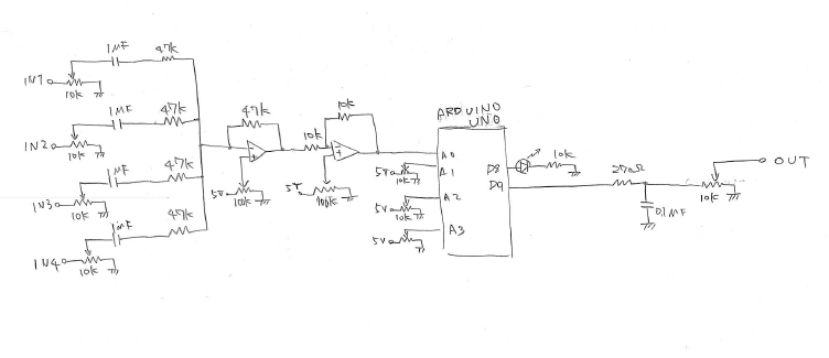
回路図
手書きで恥ずかしいですが、、
オペアンプを使った単純な加算回路です。反転増幅なので加算回路の後にもう一個
増幅度1の反転増幅させてます。
ただマイコンはマイナスの電圧を扱えないので、単電源のオペアンプを使っています
音声信号のマイナス側を持ち上げるためのバイアス電圧が必要になりますが
シュミレーター(http://www.falstad.com/circuit/ すごい便利)で出した
電圧かけてもうまくいかなかったので可変抵抗で調整できるようにしました
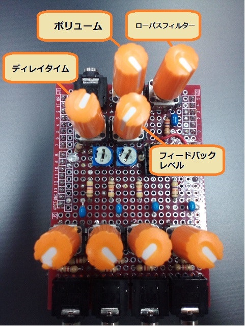
外観
送料があるので、買い置きしておいたパーツを使うから色合いがすべて同じ、、
(赤い基板にオレンジのノブ。前回作ったやつ→http://qiita.com/skyfish20ch/items/675fdeaefc623e3bab9f )
※使っていない抵抗があります(試行錯誤の跡です)
デモ
雑感
updateControl()のところで、適度にウェイト持たせないとうまく動きませんでした。
だいぶ苦労しました。わざとSerial.plintして時間かせいだりしてます。
if kDelay.redy(){
・・・
・・・
・・・
kDelay.start(300);
}
やってるのでシリアル出力はいらないかも・・・
出力音声のレベルも適度に下げておかないといけないので試行錯誤してこの値に
しました。
あんまり思ったようなディレイかかってませんが、おもしろい音になったかと思います