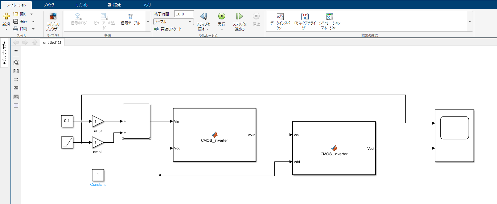
function Vout = CMOS_inverter(Vin, Vdd)
    % 定数の設定 (Setting constants)
    V_Tn = 1.0;  % NMOSのしきい値電圧 (Threshold voltage for NMOS)
    V_Tp = -1.0;  % PMOSのしきい値電圧 (Threshold voltage for PMOS)

    % 定数の設定 (Setting constants for mobility and oxide capacitance)
    mu_n = 600e-4;  % NMOSの移動度 (Electron mobility for NMOS)
    mu_p = 300e-4;  % PMOSの移動度 (Hole mobility for PMOS)
    C_ox = 3.45e-3;  % 酸化膜容量 (Oxide capacitance)

    % NMOSとPMOSのWとLを定義 (Define W and L for NMOS and PMOS)
    W_n = 10e-6;  % NMOSのチャンネル幅 (Channel width for NMOS)
    L_n = 2e-6;   % NMOSのチャンネル長 (Channel length for NMOS)
    W_p = 20e-6;  % PMOSのチャンネル幅 (Channel width for PMOS)
    L_p = 2e-6;   % PMOSのチャンネル長 (Channel length for PMOS)

    % βnとβpの計算 (Calculate βn and βp)
    beta_n = mu_n * C_ox * (W_n / L_n);
    beta_p = mu_p * C_ox * (W_p / L_p);

    % しきい値電圧Vthの計算 (Calculate Vth based on the provided formula)
    Vth = (Vdd + V_Tp + sqrt(beta_n / beta_p) * V_Tn) / (1 + sqrt(beta_n / beta_p));

    % ゲインの計算 (Calculate gain using the provided formula)
    gmp = 1e-3;  % PMOS transconductance (S)
    gmn = 1e-3;  % NMOS transconductance (S)
    rop = 10e3;  % PMOS output resistance (ohms)
    ron = 10e3;  % NMOS output resistance (ohms)
    gain = (gmp + gmn) / (1/rop + 1/ron);

    % ロジスティック関数を使ったCMOSインバーターの出力 (CMOS inverter output using logistic function)
    Vout = Vdd * (1 / (1 + exp(-gain * (Vth - Vin))));
end
メモ 理想ではない比較器
import numpy as np
import matplotlib.pyplot as plt

# 非理想的比較器のモデル関数
def non_ideal_comparator(v_in, v_th, hysteresis=0.1, slope=10):
    """
    非理想的比較器の動作をモデル化
    v_in: 入力電圧
    v_th: しきい値電圧
    hysteresis: ヒステリシス幅
    slope: 遷移のスロープ (大きいほど理想的)
    """
    # ヒステリシスを考慮
    lower_th = v_th - hysteresis / 2
    upper_th = v_th + hysteresis / 2

    # 遷移をスムーズにするためにシグモイド関数を使用
    output = 1 / (1 + np.exp(-slope * (v_in - upper_th)))  # 上限方向
    output -= 1 / (1 + np.exp(-slope * (v_in - lower_th)))  # 下限方向
    return output

# パラメータ設定
v_th = 2.5  # しきい値電圧 (例: 2.5V)
hysteresis = 0.2  # ヒステリシス幅 (例: 0.2V)
slope = 20  # スロープ (遷移の急さを調整)
v_in = np.linspace(0, 5, 500)  # 入力電圧 (0Vから5Vの範囲)

# 非理想的比較器の出力を計算
output = non_ideal_comparator(v_in, v_th, hysteresis, slope)

# プロット
plt.figure(figsize=(8, 4))
plt.plot(v_in, output, label="Non-Ideal Comparator Output")
plt.axvline(v_th, color="red", linestyle="--", label="Threshold Voltage (V_th)")
plt.axvline(v_th - hysteresis / 2, color="blue", linestyle="--", label="Lower Threshold")
plt.axvline(v_th + hysteresis / 2, color="green", linestyle="--", label="Upper Threshold")
plt.title("Non-Ideal Comparator Model")
plt.xlabel("Input Voltage (V_in) [V]")
plt.ylabel("Output")
plt.grid()
plt.legend()
plt.show()

