前回は ESP-WROOM-02 DIP化キットを使ったESP気象センサーの作り方を解説いたしました。
ESP-WROOM-02 DIP化キットを使って気象センサーを作る (Qiita@pipito-yukio)
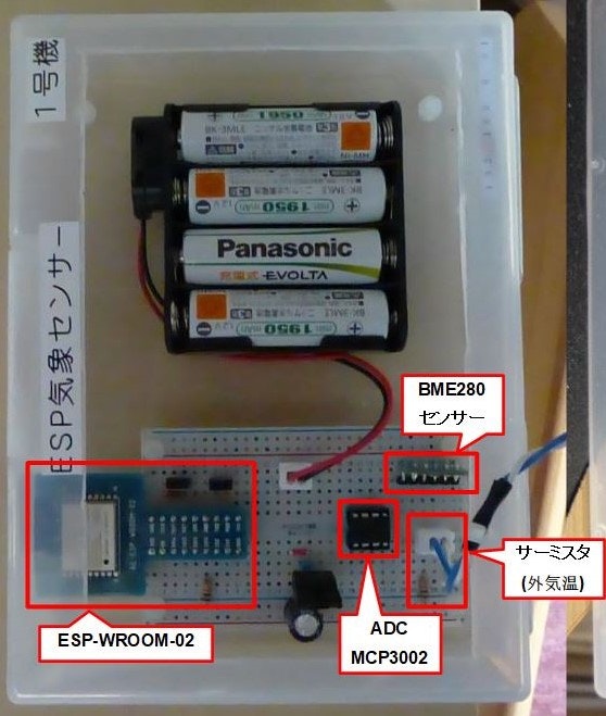
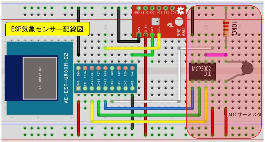
今回はESP気象センサーのサーミスタの温度をアナログコンバーター(MCP3002) を使って取得する方法を紹介します。下記はその配線図で、今回紹介するのは右側の赤枠部分となります。
参考にしたサイト
MCP3002の詳しい仕様の説明を参考にせていただきました。
【作りながら学ぶ Arduino+=電子工作入門】A-Dコンバータ その1 10ビットSPI MCP3002
参考書
ESPモジュール関連
-
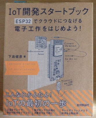
IoT 開発スタートブック ESP32でクラウドにつなげる電子工作をはじめよう!
2019年8月24日 初 版 第1刷発行 株式会社技術評論社
第6章 電力利用量を可視化する
SPI通信と MCP3004のアクセスプログラムをライブラリ化する
※この本はESP32対象ですがSPIライブラリ部分は ESP8266でもそのまま使えます。
C++ 関連
C++でのプログラムの経験が浅いため、基本的なC++プログラミングついては下記書籍で理解を深めました。
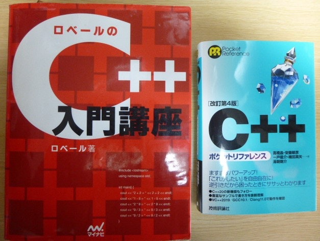
-
ローベルの C++ 入門講座
2015 年 8 月 17 日 初版第13刷発行 株式会社マイナビ
※今となっては相当古い書籍になりましたが基本的な部分はそれほど変わっていないので、初心者にとってはありがたい存在の本になっています。 -
[改定第4版] C++ポケットリファレンス
2021 年 4 月 28 日 第4版 第1刷発行
開発環境
- PC: Ubuntu 22.04
- ソースの作成とビルド: PlatformIO IDE for VSCode
- USBシリアルポートドライバーがインストール済み
/dev/ttyUSB0
$ dmesg | grep ttyUSB
[   36.050148] usb 4-1: FTDI USB Serial Device converter now attached to ttyUSB0
[ 6970.214575] ftdi_sio ttyUSB0: FTDI USB Serial Device converter now disconnected from ttyUSB0
[ 6981.870383] usb 4-1: FTDI USB Serial Device converter now attached to ttyUSB0
- ユーザーにシリアルポートのアクセス権(dialout)が必要
$ sudo adduser $USER dialout
一旦ログアウトしてから再度端末を開いて確認 ※20(dialout)
$ id
uid=1000(yukio) gid=1000(yukio) groups=1000(yukio),4(adm),20(dialout),#...以下省略
1. プロジェクトの作成
VSCodeで PIO Home ベージを立ち上げ [+ New Project] からブロジェクトを作成
PlatformIO プロジェクトファイル
[env:esp_wroom_02]
platform = espressif8266
board = esp_wroom_02
framework = arduino
monitor_port = /dev/ttyUSB0
monitor_speed = 9600
ブロジェクトディレクトリ直下に生成されるファイル群 ※main.cpp に処理を実装
.
├── .gitignore
├── .pio
│   └── build
│       ├── esp_wroom_02
│       │   └── idedata.json
│       └── project.checksum
├── .vscode
│   ├── c_cpp_properties.json
│   ├── extensions.json
│   └── launch.json
├── include
│   └── README
├── lib
│   └── README
├── platformio.ini
├── src
│   └── main.cpp
└── test
    └── README
VSCodeにPlatformIOプラグインをインストールした時に、$HOME/.platformio 配下にツールチェーンとESP関連のライブラリがインストールされます。
1-1. アナログコンバーター(MCP3002)の読取り処理
MCP3002 仕様書の抜粋
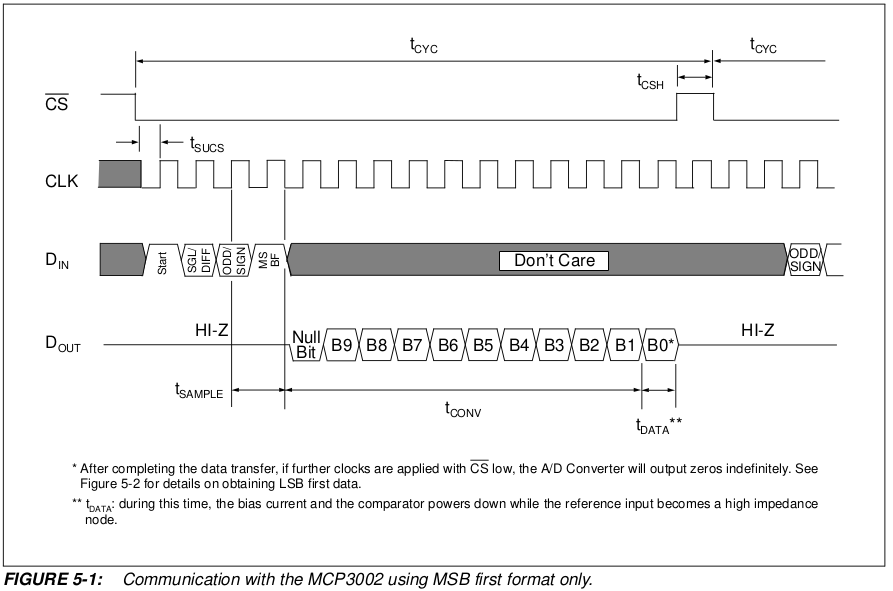
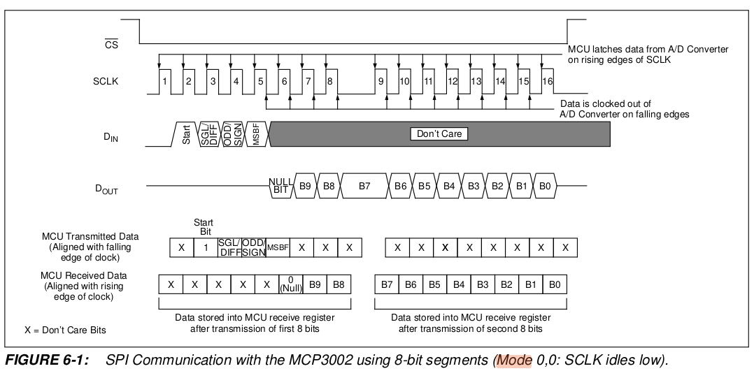
上記FIGURE 5-1, 6-1 からアナログ値読取り関数の処理内容をDoc部分に記載しました。
#include <Arduino.h>
#include <SPI.h>

// MCP3002 ADC input Channel
const uint8_t CHANNEL_THERM = 0;

SPISettings settings(1000000, MSBFIRST, SPI_MODE0);

/**
 * ADCからをバイト単位で読み込みアナログ値を計算
 * MCP3002: FIGURE 6-1 (Mode 0,0: SCLK idles low)
 * [Din] コマンドデータ生成: 2byte
 * 1st byte
 * Ch0: [0,1,1,0,1,x,x,x] -> x,1[start],1[SGL/DIFF],(0|1)[ODD/SIGN],1[MSBF],x,x,x
 * Ch1: [0,1,1,1,1,x,x,x]
 * 2nd byte: Dummy
 *      [x,x,x,x,x,x,x,x] -> 0x0
 * ※x は何でも良いので 0
 * [Dout]
 * 最初の8bit: [x,x,x,x,x,0(null),B9,B8] & 0x03 で B9,B8を取り出す
 * 最後の8bit: [B7,B6,B5,B4,B3,B2,B1,B0]
 * (*1) Null bit
 * @param[in] ch ADC Channel
 * @return uint16_t アナログ値
 */
uint16_t readValue(uint8_t ch) {
   SPI.beginTransaction(settings);
   digitalWrite(PIN_SPI_SS, LOW);
   // Read analog value.
   byte _highByte = SPI.transfer(0b01101000 | (ch << 4));
   byte _lowByte = SPI.transfer(0x00);
   digitalWrite(PIN_SPI_SS, HIGH);
   SPI.endTransaction();
   u_int16_t adcVal = ((_highByte & 0x03) << 8) | _lowByte;
   return adcVal;
}
- アナログコンバーターの測定値(アナログ値)から電圧を計算する関数
ADC_VREF: アナログコンバータのリレファレンス電圧
※1 テスターで測定した値は若干小さい値でしたが 3.3 v としています。
※2 本来は測定した値にすべきと思いますが、計算後の誤差は許容範囲内とします。
const ADC_VREF = 3.3;

float getVoltage(uint16_t adcVal, adcVRef) {
   return adcVal * adcVRef / 1024.0;
}
1-2. サーミスタの温度計算関数
- サーミスタのある温度における抵抗値の計算方法
※秋月電子のサーミスタ商品ページからダウンロードしたのPDFからの抜粋
T0 ℃での抵抗値が R0 Ωのサーミスタにおける、温度T0 ℃の抵抗値
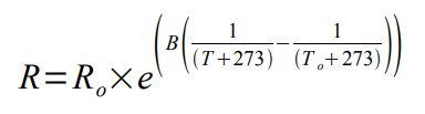
上記式から気温Tを求める
- rx = 分圧抵抗値 ☓ ((サーミスタ電圧 - ADC出力電圧) / ADC出力電圧)
- xa = log (rx / 25℃時のサーミスタ抵抗値) / サーミスタのB定数
- 気温T = (1 / (xa + 1/(25+273))) - 273
// Thermister section
const float THERM_V = 3.3;  // サーミスタ電圧
const float THERM_B = 3435.0;
const float THERM_R0 = 10000.0; // サーミスタの25℃時の抵抗値
const float THERM_R1 = 10000.0; // 分圧抵抗値
const float THERM_READ_INVALID = -9999.0;

float getThermTemp() {
   double rx, xa, temp;
   uint16_t adcVal = readValue(CHANNEL_THERM);
   float outVolt = getVoltage(adcVal, ADC_VREF);
   Serial.print("Therm.outVolt: ");
   Serial.print(outVolt, 3);
   Serial.println(" V ");
   if (adcVal == 0 || outVolt < 0.01) {
      Serial.println("Thermister read invalid!");
      return THERM_READ_INVALID;
   }

   rx = THERM_R1 * ((THERM_V - outVolt) / outVolt);
   xa = log(rx / THERM_R0) / THERM_B;
   temp = (1 / (xa + 0.00336)) - 273;
   Serial.print("rx: ");
   Serial.print(rx);
   Serial.print(", xa: ");
   Serial.println(xa, 6);
   return (float)temp;
}
1-3. 初期化処理
- CSピンを出力モードに設定
- CSピンをHIGHに設定
- SPIライブラリ初期化 (デフオルト ※ESP8266のピン定義)
void setup() {
  Serial.begin(9600);
  Serial1.println("Start Thermistor and IC sensor with adc mcp3002");

  pinMode(PIN_SPI_SS, OUTPUT);
  digitalWrite(PIN_SPI_SS, HIGH);
  SPI.begin();
  // Wait MCP3002
  delay(500);
}
1-4. サーミスタの測定気温出力
30秒間隔でシリアルポートに測定値を出力
void loop() {
   float thermTemper = getThermTemp();
   Serial.print("Thermistor.Temp:");
   Serial.println(thermTemper, 1);
   delay(30000);
}
2. アナログコンバーター処理をクラス化する
ESP気象センサーではWi-Fiのセットアップ、BME280センサーの測定、各センサーの測定値をUDPパケットに出力するなど処理が多岐にわたるためアナログコンバーター処理部分をクラス化します。
参考にしたライブラリ
2-1.ヘッダー定義
- ADC読み取りデータを共用体で定義
- デストラクタ ※継承を前提としない
- 電圧値に変換するメソッドを追加 ※公開されているMCP系ライブラリでは定義されていない
#ifndef __SimpleMCP3002_h__
#define __SimpleMCP3002_h__
#include <Arduino.h>
#include <SPI.h>

union ReadData {
    uint16_t value;
    struct {
        uint8_t lowByte;
        uint8_t highByte;
    };
};

class SimpleMCP3002 {
public:
    // static const variables
    static const uint16_t RESOLUTION = 1024;
    static const int8_t INVALID_READ = -1; // Valid read: 0 - 1023
    // Constructor
    SimpleMCP3002(float vRef);
    // Destructor
    ~SimpleMCP3002(){};
    // Startup initialize
    void begin();
    // Public method
    uint16_t analogRead(uint8_t ch);
    // Utility method
    float getVolt(uint16_t adcVal);
    // DEBUG Use
    ReadData getReadData() { return mData; };

private:
    // member variable
    uint8_t mCsPin;
    float mVRef;
    SPISettings mSettings;
    // DEBUG Use
    ReadData mData;
};

#endif // __SimpleMCP3002_h__
2-2. クラスの処理実装
-
コンストラクタ
- CS ピンをフィールドに設定
- リファレンス電圧をフィールドに設定
- SPISettings(clock, bitOrder, dataMode) をフィールドに設定
※ SPI.h 参照
-
クラスの初期化
- CSピンを出力に設定
- CSピンをHIGHに設定
- SPIクラスの初期化
#include "SimpleMCP3002.h"

// Constructor
SimpleMCP3002::SimpleMCP3002(float vRef) :
    mCsPin(PIN_SPI_SS),
    mVRef(vRef),
    mSettings(SPISettings(1000000, MSBFIRST, SPI_MODE0)/*Clock Frequency: 1MHz */) {
}

void SimpleMCP3002::begin(void) {
    pinMode(mCsPin, OUTPUT);
    digitalWrite(mCsPin, HIGH);
    SPI.begin();
}

uint16_t SimpleMCP3002::analogRead(uint8_t ch) {
    SPI.beginTransaction(mSettings);
    digitalWrite(mCsPin, LOW);
    byte _highByte = SPI.transfer(0b01101000 | (ch << 4));
    byte _lowByte = SPI.transfer(0x00);
    digitalWrite(mCsPin, HIGH);
    SPI.endTransaction();
    // Read analog value.
    mData.highByte = _highByte & 0x03;
    mData.lowByte = _lowByte;
    // MCP3002: 0 - 1023
    if (mData.value >= 0 && mData.value < RESOLUTION) {
        return mData.value;
    }

    return SimpleMCP3002::INVALID_READ;
}

float SimpleMCP3002::getVolt(uint16_t adcVal) {
    return adcVal * mVRef / RESOLUTION;
}
2-3.SimpleMCP3002クラスを使った実装
getSamplingAdcValue()
アナログコンバーターから取得するサンプリング回数を10回とし、平均値をアナログ値とする関数を追加
#include <Arduino.h>
#include "SimpleMCP3002.h"

// MCP3002: channel=0,1
const uint8_t ADC_SAMPLES = 10;
const uint8_t CH0 = 0;
const float ADC_VREF = 3.3;
// Thermister section
const float THERM_V = 3.3;
const float THERM_B = 3435.0;
const float THERM_R0 = 10000.0;
// Divide register 10k
const float THERM_R1 = 10000.0;
const float THERM_READ_INVALID = -9999.0;

SimpleMCP3002 adc(ADC_VREF);

// サンプリング回数分の平均値を取得
float getSamplingAdcValue(uint8_t ch, SimpleMCP3002 &mcp) {
  int adcSamples[ADC_SAMPLES];
  int i;
  Serial.print("CH<");
  Serial.print(ch);
  Serial.print(">: [");
  for (i = 0; i < ADC_SAMPLES; i++) {
    adcSamples[i] = mcp.analogRead(ch);
    Serial.print(adcSamples[i]);
    if (i < (ADC_SAMPLES - 1)) {
      Serial.print(",");
    }
    delay(30);
  }
  Serial.print("], mean adc: ");
  uint16_t adcTotal = 0;
  for (i = 0; i < ADC_SAMPLES; i++) {
    adcTotal += adcSamples[i];
  }
  uint16_t meanAdc = round(1.0 * adcTotal / ADC_SAMPLES);
  Serial.println(meanAdc);
  return meanAdc;
}

// サーミスタの気温計算
float getThermTemp() {
  double rx, xa, temp;
  uint16_t adcVal = getSamplingAdcValue(CH0, adc);
  float outVolt = adc.getVolt(adcVal);
  Serial.print("Therm.outVolt: ");
  Serial.print(outVolt, 3);
  Serial.println(" V ");
  if (adcVal == 0 || outVolt < 0.01) {
    Serial.println("Thermister read invalid!");
    return THERM_READ_INVALID;
  }

  rx = THERM_R1 * ((THERM_V - outVolt) / outVolt);
  xa = log(rx / THERM_R0) / THERM_B;
  temp = (1 / (xa + 0.00336)) - 273;
  Serial.print("rx: ");
  Serial.print(rx);
  Serial.print(", xa: ");
  Serial.println(xa, 6);
  return (float)temp;
}

void setup() {
  Serial.begin(9600);
  Serial1.println("-- Thermister and IC sensors with adc mcp3002 --");
  adc.begin();

  Serial.println("--START--");
  // Wait MCP3002
  delay(500);
}

void loop() {
  // Measure Thermister
  float thermTemp = getThermTemp();
  Serial.print("Therm Temp:");
  Serial.println(thermTemp, 1);
  delay(30000);
}
3. 検証用のpythonスクリプト
- 実行環境: Raspberry Pi Zero
※Ubuntu PC からSSHでログインして検証用スクリプトを実行 - システムライブラリ: pigpioサービスがインストール済み
- Python 3.7.3: 仮想環境に pigpio Pythonライブラリがインストール済み
(py37_pigpio)$ pip install pigpio
参考書
-
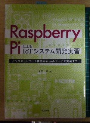
Raspberry Pi による IoT システム開発実習
2022 年 10 月 26 日 第1版第1刷発行 森北出版株式会社
[CHAPTER 5] アナログ・ディジタル変換 (AD 変換)
※1 使用しているADCは MCP3208 です。図入りの説明がとても良くわかりやすいです。
※2 この章で使用している Pythonライブラリは spidev ですが、以降で紹介する実装は pigpioに合わせて改変しています。
3-1. SPI処理クラス
(1) ADコンバーターの型定義とコマンド生成、アナログ値読み取り関数の定義
from enum import Enum

"""
ADコンバータ共通定数、関数
"""


class ADC(Enum):
    MCP3002 = 0
    MCP3208 = 4


def _create_cmd_3002(ch):
    """
    コマンドデータ生成: 2byte
     (1)最初の8bit: [x,1(*1),1(*2),0,(*3), 1(*4),x,x,x]
     (2)最後の8bit: [0,0,0,0,0,0,0,0] ※クロック生成用
        x: 何でもかまわないが 0を設定
       (*1) Start bit:1
       (*2) SIGL/DIFF: Single End=1, Differential=0
       (*3) ODD/SIGN: 0 | 1
    :param ch: アナログ入力チャネル (0 | 1)の2チャネル
    :return: 2バイトのリスト
    """
    return [(0x68 | ch << 4), 0x00]


def _create_cmd_3208(ch):
    """
    コマンドデータ生成: 3byte
     (1)最初の8bit: [0,0,0,0,0,1(*1),1(*2),D2] -> 0x06 | 0x07
     (2)次の8bit:   [D1,D0,0,0,0,0,0,0]        -> 0x00, 0x04, 0x08, 0x0c
     (3)最後の8bit: [0,0,0,0,0,0,0,0]          -> 0x00
       (*1) Start bit:1
       (*2) SIGL/DIFF: Single End=1, Differential=0
       D2[=0|1], D1[=0|1], D0[=0|1]: Channel0〜7の選択
       ch  D2 | D1 | D0
        0  0    0    0
        1  0    0    1
        2  0    1    0
        3  0    1    1
        4  1    0    0
        5  1    0    1
        6  1    1    0
        7  1    1    1
       (生成例)
          ch=5, [0x07, 0x40, 0x00]
    :param ch: アナログ入力チャネル
    :return: コマンドデータ(リスト)
    """
    return [0b00000110 + (ch >> 2), (ch & 0b011) << 6, 0]


def _analog_read_3002(r_data):
    """
    アナログ値を計算
     ※以下はDatasheetに記載あり
     (1)最初の8bit(r_data[0]): [x,x,x,x,x,0(*1),B9,B8]
     (2)最後の8bit(r_data[1]): [B7,B6,B5,B4,B3,B2,B1,B0]
    :param r_data: 2バイト
    :return: アナログ値10bit
    """
    return (r_data[0] << 8 | r_data[1]) & 0x3ff


def _analog_read_3208(r_data):
    """
    アナログ値を計算
     ※以下はDatasheetに記載あり
     (1)最初の8bit(r_data[0]): [x,x,x,x,x,x,x,x] ※読み捨て
     (2)次の8bit(r_data[1]): [x,x,x,0(*1),B11,B10,B9,B8]
     (3)最後の8bit(r_data[2]): [B7,B6,B5,B4,B3,B2,B1,B0]
       (*1) Null bit
    :param r_data: 3バイト
    :return: アナログ値12bit
    """
    return (r_data[1] & 0x0f) << 8 | r_data[2]


RESOLUTION = {ADC.MCP3002: 1024, ADC.MCP3208: 4096}
CMD_FUNC = {ADC.MCP3002: _create_cmd_3002, ADC.MCP3208: _create_cmd_3208}
READ_FUNC = {ADC.MCP3002: _analog_read_3002, ADC.MCP3208: _analog_read_3208}
(2) MCPアナログコンバーター処理クラス
import logging
import pigpio
from .mcp3000base import ADC, RESOLUTION, CMD_FUNC, READ_FUNC

"""
ADコンバータ(SPIインターフェース)
MCP3000シリーズ用制御クラス

(ライブラリ) pigpio
spi_open(spi_channel, baud, spi_flags)

The Pi has two SPI peripherals: main and auxiliary.
         MISO  MOSI  SCLK  CE0 CE1 CE2
Main SPI:   9    10    11    8   7   -
Aux SPI:   19    20    21   18  17  16

:parameters:
  spi_channel:= 0-1 (0-2 for the auxiliary SPI)
  baud       := 32K - 125M
  spi_flags  :=
    spi_flags consists of the least significant 22 bits.
    21 20 19 18 17 16 15 14 13 12 11 10  9  8  7  6  5  4  3  2  1  0
     b  b  b  b  b  b  R  T  n  n  n  n  W  A u2 u1 u0 p2 p1 p0  m  m

(例)
 pi.spi_open(0, 1000000, 0)   # CE0[GPIO8(16)], 1Mbps, main SPI
 pi.spi_open(1, 1000000, 0)   # CE1[GPIO7(18)], 1Mbps, main SPI
"""

# Dataシートから持ってくる: 電源電圧=3.3Vとする
# MCP3208
# Sample rate Vdd=VRef=5V   100k sps (sample per seconds)
#   **計算**  Vdd=VRef=3.3  60k sps
#     資料    Vdd=VRef=2.7  50k sps
# MCP3002
# Sample rate Vdd=VRef=5V   200k sps
#   **計算**  Vdd=VRef=3.3  100k sps
#             Vdd=VRef=2.7  75k sps
BAUD_DEFAULT = 100000  # 100kHz


class MCP3000:
    def __init__(self, ce, baud=BAUD_DEFAULT, v_ref=3.3, adc=ADC.MCP3002, logger=None):
        self.pi = pigpio.pi()
        self.spi_handle = self.pi.spi_open(ce, baud, 0)
        self.v_ref = v_ref
        self.cmd_func = CMD_FUNC[adc]
        self.read_func = READ_FUNC[adc]
        self.resolution = RESOLUTION[adc]
        self.logger = logger
        self.debug_once = logger is not None and (logger.getEffectiveLevel() <= logging.DEBUG)
        if self.debug_once:
            self.logger.debug("spi_handle: {}".format(self.spi_handle))
            self.logger.debug("v_ref: {}V, resolution: {}".format(self.v_ref, self.resolution))
            self.logger.debug("cmd_func: {}".format(self.cmd_func))
            self.logger.debug("read_func: {}".format(self.read_func))

    def analog_read(self, ch):
        din = self.cmd_func(ch)
        if self.debug_once:
            self.logger.debug("ch: {}, din: {}".format(ch, din))
        # spi_xfer(handle, data)
        (count, r_data) = self.pi.spi_xfer(self.spi_handle, din)
        adc_value = self.read_func(r_data)
        if self.debug_once:
            self.logger.debug("count: {}".format(count))
            for i in range(count):
                self.logger.debug("r_data[{}]: {:#04x}".format(i, r_data[i]))
            self.logger.debug("adc_value: [{0}] - {0:#04x}".format(adc_value))
        return adc_value

    def _adc_to_volt(self, adc_value):
        return adc_value * self.v_ref / float(self.resolution)

    def get_volt(self, ch):
        adc_value = self.analog_read(ch)
        volt = self._adc_to_volt(adc_value)
        return volt

    def cleanup(self):
        self.pi.spi_close(self.spi_handle)
        self.pi.stop()
(3) サーミスタの温度計算関数
※計算式は 1-2. サーミスタの温度計算関数 と同じです
import math

""" サーミスタ温度取得関数 """

REGISTER_10K = 10000
_T0_25 = 25.0
_T_KELVIN = 273


def temperature_thermistor(v_out, r1, b0, t0=_T0_25, r0=REGISTER_10K, v_ref=3.3, logger=None):
    """
    サーミスタの測定温度を計算
    :param v_out: 測定電圧 (ADコンバータ)
    :param r1: サーミスタに接続した抵抗(Ω)
    :param b0: サーミスタのB定数
    :param t0: サーミスタ25℃
    :param r0: t0の時の抵抗(Ω)
    :param v_ref: 電源電圧
    :return: 測定温度 [℃]
    """
    rx = ((v_ref - v_out) / v_out) * r1
    xa = math.log(float(rx) / float(r0)) / float(b0)
    xb = 1 / (_T_KELVIN + t0)
    temp = (1 / (xa + xb)) - _T_KELVIN
    if logger is not None:
        logger.debug("rx: {:#.2f}, xa: {:#.5f}, xb: {:#.5f}, temp: {:#.2f}".format(rx, xa, xb, temp))
    return temp
3-2.サーミスタ温度測定メインスクリプト
スクリプトの入力パラメータ
- 使用するADC: --adc-name mcp3208(デフォルト) | mcp3002
- 測定間隔: --interval 秒
import argparse
import argparse
import time
from lib.mcp3000 import MCP3000
from lib.mcp3000base import ADC
from lib.analogtempsensors import temperature_thermistor
from log import logsetting

"""
サーミスタの温度測定
[部品]
  1.ADコンバータ
   1-1.MCP3208: 分解能12bit, 8CH
   1-2.MCP3002: 分解能10bit, 2CH
  2.サーミスター + 10KΩ
   2-1.103AT
    (測定範囲) 温度: -50 〜110 C, B定数:3435
"""

logger = logsetting.create_logger("main_app")

SPI_BUS = 0
SPI_CE0 = 0
# 測定チャネル: サーミスタ
CH_THRM_103AT = 0
# サーミスタに接続する抵抗(Ω)
R1 = 10000 # 10KΩ
# B定数
B0_1 = 3435

if __name__ == '__main__':
    parser = argparse.ArgumentParser()
    parser.add_argument("--adc-name", type=str, choices=['mcp3208', 'mcp3002'], default='mcp3208',
                        help="ADC name.")
    parser.add_argument("--interval", type=float, default=5.0, help="Measuring interval.")
    args = parser.parse_args()
    logger.info(args)

    adc_type = ADC.MCP3002 if args.adc_name == "mcp3002" else ADC.MCP3208
    sample_speed = 100000 if adc_type == ADC.MCP3002 else 60000
    adc = MCP3000(SPI_CE0, baud=sample_speed, adc=adc_type, logger=logger)
    interval = args.interval

    logger.info("adc: {}".format(adc))
    try:
        time.sleep(1.0)
        debug_count = 0
        while True:
            volt0 = adc.get_volt(CH_THRM_103AT)
            logger.info("volt: {:#2.2f}".format(volt0))
            if volt0 > 0:
                deg = temperature_thermistor(volt0, r1=R1, b0=B0_1, logger=logger)
                logger.info("Temp {:#3.1f}".format(deg))
            debug_count += 1
            if debug_count >= 3:
                # DEBUG OFF
                adc.debug_once = False
            time.sleep(interval)
    except KeyboardInterrupt:
        adc.cleanup()
    except Exception as exp:
        adc.cleanup()
        raise exp
4. スクリプトの実行
4-1. ESP-WROOM-02 開発ボード
PlatformioIDEでビルドし開発ボードに書き込みします
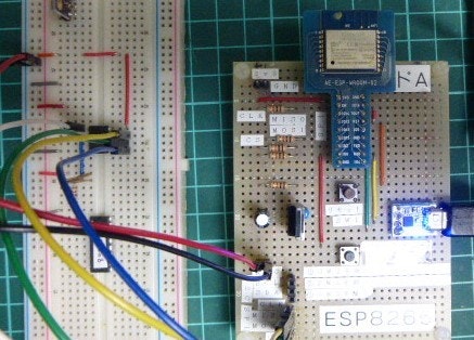
書き込み完了後にシリアルモニタに切り替えし、開発ボードのリセットボタンを押して測定値の出力を確認します
Therm.outVolt: 1.421 V
rx: 13219.96, xa: 0.000081
Thermistor.Temp:18.3
Therm.outVolt: 1.412 V
rx: 13378.99, xa: 0.000085
Thermistor.Temp:18.0
Therm.outVolt: 1.412 V
rx: 13378.99, xa: 0.000085
Thermistor.Temp:18.0
Therm.outVolt: 1.408 V
rx: 13432.49, xa: 0.000086
Thermistor.Temp:17.9
Therm.outVolt: 1.405 V
rx: 13486.24, xa: 0.000087
Thermistor.Temp:17.8
Therm.outVolt: 1.405 V
rx: 13486.24, xa: 0.000087
Thermistor.Temp:17.8
4-2. Raspberry Pi Zero
Raspberry Pi zero で ESP-WROOM-02 開発ボードでの出力値(気温)が正しいか検証します
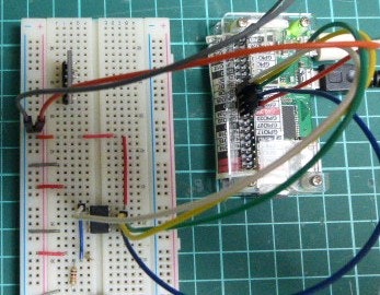
開発PC から Raspberry Pi zero に SSHでログインし、pythonスクリプトを実行
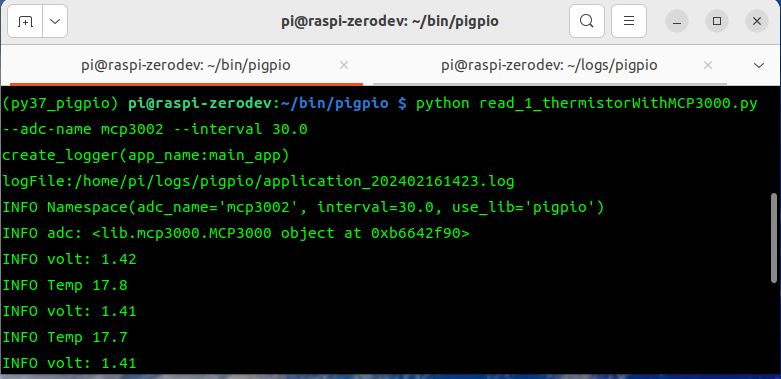
ESP-WROOM-02 開発ボードで出力された値に近い値がログ出力されています
pi@raspi-zerodev:~/logs/pigpio $ tail -f application_202402161423.log
2024-02-16 14:23:41 INFO read_1_thermistorWithMCP3000.py(73)[<module>] Namespace(adc_name='mcp3002', interval=30.0, use_lib='pigpio')
2024-02-16 14:23:41 DEBUG mcp3000.py(53)[__init__] spi_handle: 0
2024-02-16 14:23:41 DEBUG mcp3000.py(54)[__init__] v_ref: 3.3V, resolution: 1024
2024-02-16 14:23:41 DEBUG mcp3000.py(55)[__init__] cmd_func: <function _create_cmd_3002 at 0xb6789270>
2024-02-16 14:23:41 DEBUG mcp3000.py(56)[__init__] read_func: <function _analog_read_3002 at 0xb67674f8>
2024-02-16 14:23:41 INFO read_1_thermistorWithMCP3000.py(85)[<module>] adc: <lib.mcp3000.MCP3000 object at 0xb6642f90>
2024-02-16 14:23:42 DEBUG mcp3000.py(61)[analog_read] ch: 0, din: [104, 0]
2024-02-16 14:23:42 DEBUG mcp3000.py(66)[analog_read] count: 2
2024-02-16 14:23:42 DEBUG mcp3000.py(68)[analog_read] r_data[0]: 0x01
2024-02-16 14:23:42 DEBUG mcp3000.py(68)[analog_read] r_data[1]: 0xb7
2024-02-16 14:23:42 DEBUG mcp3000.py(69)[analog_read] adc_value: [439] - 0x1b7
2024-02-16 14:23:42 INFO read_1_thermistorWithMCP3000.py(91)[<module>] volt: 1.42
2024-02-16 14:23:42 DEBUG analogtempsensors.py(52)[temperature_thermistor] rx: 13302.96, xa: 0.00008, xb: 0.00335, temp: 17.79
2024-02-16 14:23:42 INFO read_1_thermistorWithMCP3000.py(94)[<module>] Temp 17.8
2024-02-16 14:24:14 DEBUG mcp3000.py(61)[analog_read] ch: 0, din: [104, 0]
2024-02-16 14:24:14 DEBUG mcp3000.py(66)[analog_read] count: 2
2024-02-16 14:24:14 DEBUG mcp3000.py(68)[analog_read] r_data[0]: 0x01
2024-02-16 14:24:14 DEBUG mcp3000.py(68)[analog_read] r_data[1]: 0xb6
2024-02-16 14:24:14 DEBUG mcp3000.py(69)[analog_read] adc_value: [438] - 0x1b6
2024-02-16 14:24:14 INFO read_1_thermistorWithMCP3000.py(91)[<module>] volt: 1.41
2024-02-16 14:24:14 DEBUG analogtempsensors.py(52)[temperature_thermistor] rx: 13356.16, xa: 0.00008, xb: 0.00335, temp: 17.69
2024-02-16 14:24:14 INFO read_1_thermistorWithMCP3000.py(94)[<module>] Temp 17.7
Arduino IDE を使用したコーディングについて
同じ処理をコーディングするのに Raspberry Pi(Python)と比べると ESPモジュールを使った処理の実装はかなり大変です。なのに Arduino IDE のエディターがあまりにも貧弱なので途中から VSCode + PlatformIO IED に切り替えました。少なくともプロが開発で使用するIDEではないと感じました。
SPI、I2C、UARTを使った処理は Raspberry Pi 側でも開発が可能なので検証用としてPythonライブラリを作成しておいたほうが良いと思います。
次回はいよいよ ESP気象センサーの全ソースコードを解説する予定です。
Raspberry Pi用のSPI用カスタムライブラリのソースコードは下記GitHubで公開しています。
GitHub pipito-yuko: home_weather_sensors/raspi_zero/bin/pigpio/lib
bin/pigpio/lib/
  analogtempsensors.py
  mcp3000.py
  mcp3000base.py