ESP32 の GPIO12 は内蔵フラッシュチップの電圧選択になっている。
「ESP32 のGPIOピンのクセ」
https://qiita.com/nanbuwks/items/0c5ee8fb4cf10d9c59e1
ここの GPIO12 の処理のために、動作がヘンテコになったというお話。
環境
- 開発環境
- Arduino 1.8.13
- Linux 版
- ポータブル化済
- esp32 Espressif Systems 1.0.4
- 母艦 Ubuntu 22.04 LTS
- Arduino 1.8.13
- ライブラリ
- EEPROM.h
- portable/packages/esp32/hardware/esp32/1.0.4/libraries/EEPROM/src/EEPROM.h かな?
- ハードウェア
- ESP32-WROOM32-E
回路
右上がESP32。

GPIO12はロータリーエンコーダーにつながっている。
このロータリーエンコーダーをPEC11L-4225F-S0015 から PEC11L-4125F-S0020 に変更したら症状が発生した。
症状1:書き込み時にエラー
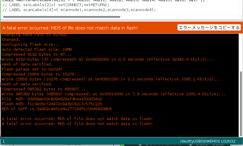
環境設定の状況

A fatal error occurred: MD5 of file does not match data in flash!
いつもというわけではなく、書き込めたり書き込めなかったりする。
症状2:EEPROM に保存できない
一見保存できているように見えるが、再起動すると過去の値に戻っている
コード
(抜粋)
#include <EEPROM.h>
#include <RotaryEncoder.h>
#define ENCODER1_A_PIN 34
#define ENCODER1_B_PIN 35
#define ENCODER1_SWITCH_PIN 25
#define ENCODER2_A_PIN 12
#define ENCODER2_B_PIN 13
#define ENCODER2_SWITCH_PIN 14
RotaryEncoder encoder1(ENCODER1_A_PIN, ENCODER1_B_PIN);
RotaryEncoder encoder2(ENCODER2_A_PIN, ENCODER2_B_PIN);

void eeprom_write() {
  // EEPROM操作のために割り込みを停止
  detachInterrupt(ENCODER1_A_PIN);
  detachInterrupt(ENCODER1_B_PIN);
  detachInterrupt(ENCODER1_SWITCH_PIN);
  detachInterrupt(ENCODER2_A_PIN);
  detachInterrupt(ENCODER2_B_PIN);   // rotary_encoder
  detachInterrupt(ENCODER2_SWITCH_PIN);  // rotary_encoder push switch

  int data[14];
  data[0]  = ・・・
  data[1]  = ・・・
.
.
  data[12]  = ・・・
  data[13] = ・・・
  int n = 0;
  Serial.println("EEPROM WRITE");
  for (int i = 0; i < 14; i++) {
    EEPROM.put(n, data[i]);
    Serial.print(i);
    Serial.print(":");
    Serial.println(data[i]);
    n += 4; // 4バイト毎
  }
  delay(100);
  EEPROM.commit(); // EEPROMに書き込み確定
  // 割り込み再設定
  attachInterrupt(ENCODER1_A_PIN, ISR, CHANGE);   // rotary_encoder
  attachInterrupt(ENCODER1_B_PIN, ISR, CHANGE);   // rotary_encoder
  attachInterrupt(ENCODER1_SWITCH_PIN, RELEASE1, RISING);  // rotary_encoder push switch
  attachInterrupt(ENCODER2_A_PIN, ISR, CHANGE);   // rotary_encoder
  attachInterrupt(ENCODER2_B_PIN, ISR, CHANGE);   // rotary_encoder
  attachInterrupt(ENCODER2_SWITCH_PIN, RELEASE2, RISING);  // rotary_encoder push switch
}

//------------------------------------------------------------------------------
void setup() {

  Serial.begin(115200);
  pinMode(ENCODER1_SWITCH_PIN, INPUT_PULLUP);
  pinMode(ENCODER2_SWITCH_PIN, INPUT_PULLUP);

  attachInterrupt(ENCODER1_A_PIN, ISR, CHANGE);   // rotary_encoder
  attachInterrupt(ENCODER1_B_PIN, ISR, CHANGE);   // rotary_encoder
  attachInterrupt(ENCODER1_SWITCH_PIN, RELEASE1, RISING);  // rotary_encoder push switch
  attachInterrupt(ENCODER2_A_PIN, ISR, CHANGE);   // rotary_encoder
  attachInterrupt(ENCODER2_B_PIN, ISR, CHANGE);   // rotary_encoder
  attachInterrupt(ENCODER2_SWITCH_PIN, RELEASE2, RISING);  // rotary_encoder push switch

  Serial.println("interrupt set");

  EEPROM.begin(56); // int 4 byte x 14

.
.
.
解決策
「ESP32 ブート時のGPIO12によるFLASH電圧設定機能を無効化する - chakokuのブログ(rev4)」
https://chakoku.hatenablog.com/entry/2020/01/25/234359
に沿って、内部ヒューズを設定して GPIO12 での機能を無効化します。
設定ツールは以下にあります。
https://github.com/espressif/esptool
サイトに行って、esptool-master.zip をダウンロードし、解凍します。
$ espefuse.py -p /dev/ttyUSB0 summary
もし以下のようにモジュールが無いエラーが出た場合は、
.
.
    import ecdsa
ModuleNotFoundError: No module named 'ecdsa'
必要なモジュールをインストールします。
Ubuntu22.04 の場合は以下が必要で、
- ecdsa ( 楕円曲線デジタル署名アルゴリズム )
- bitstring
- reedsolo
以下のようにしてインストールします。
$ sudo apt install python3-ecdsa python3-bitstring
$ sudo pip3 install reedsolo
Raspberry Pi OS Lite Release date: October 10th 2023
の場合は、以下が必要でした。
- cryptography
- ecdsa ( 楕円曲線デジタル署名アルゴリズム )
- bitstring
- serial
- yaml
11- reedsolo
以下のようにしてインストールします。
$ sudo apt install python3-pip python3-cryptography python3-ecdsa python3-bitstring serial yaml
$ sudo pip3 install reedsolo
Ubuntu でない場合は pip などでインストールします。
正常に実行できたら、最後にGPIO12の設定が表示されます。
espefuse.py v4.5
Connecting.....
Detecting chip type... Unsupported detection protocol, switching and trying again...
Connecting...
Detecting chip type... ESP32

=== Run "summary" command ===
EFUSE_NAME (Block) Description  = [Meaningful Value] [Readable/Writeable] (Hex Value)
----------------------------------------------------------------------------------------
Calibration fuses:
BLK3_PART_RESERVE (BLOCK0):                        BLOCK3 partially served for ADC calibration data   = False R/W (0b0)
ADC_VREF (BLOCK0):                                 Voltage reference calibration                      = 1107 R/W (0b00001)

Config fuses:
XPD_SDIO_FORCE (BLOCK0):                           Ignore MTDI pin (GPIO12) for VDD_SDIO on reset     = False R/W (0b0)
XPD_SDIO_REG (BLOCK0):                             If XPD_SDIO_FORCE, enable VDD_SDIO reg on reset    = False R/W (0b0)
XPD_SDIO_TIEH (BLOCK0):                            If XPD_SDIO_FORCE & XPD_SDIO_REG                   = 1.8V R/W (0b0)
CLK8M_FREQ (BLOCK0):                               8MHz clock freq override                           = 51 R/W (0x33)
.
.
.
DISABLE_DL_ENCRYPT (BLOCK0):                       Disable flash encryption in UART bootloader        = False R/W (0b0)
DISABLE_DL_DECRYPT (BLOCK0):                       Disable flash decryption in UART bootloader        = False R/W (0b0)
DISABLE_DL_CACHE (BLOCK0):                         Disable flash cache in UART bootloader             = False R/W (0b0)
BLOCK1 (BLOCK1):                                   Flash encryption key
   = 00 00 00 00 00 00 00 00 00 00 00 00 00 00 00 00 00 00 00 00 00 00 00 00 00 00 00 00 00 00 00 00 R/W
BLOCK2 (BLOCK2):                                   Secure boot key
   = 00 00 00 00 00 00 00 00 00 00 00 00 00 00 00 00 00 00 00 00 00 00 00 00 00 00 00 00 00 00 00 00 R/W
BLOCK3 (BLOCK3):                                   Variable Block 3
   = 00 00 00 00 00 00 00 00 00 00 00 00 00 00 00 00 00 00 00 00 00 00 00 00 00 00 00 00 00 00 00 00 R/W

Flash voltage (VDD_SDIO) determined by GPIO12 on reset
以下のようにして3.3Vに固定すると、解決します。
$ espefuse.py -p /dev/ttyUSB0 set_flash_voltage 3.3V
espefuse.py v4.5
Connecting...
Detecting chip type... Unsupported detection protocol, switching and trying again...
Connecting...
Detecting chip type... ESP32

=== Run "set_flash_voltage" command ===
Enable internal flash voltage regulator (VDD_SDIO) to 3.3V.

VDD_SDIO setting complete.

Check all blocks for burn...
idx, BLOCK_NAME,          Conclusion
[00] BLOCK0               is not empty
	(written ): 0x0000000401100000000001330000a200001708d1f9813b0000000000
	(to write): 0x00000000000000000001c00000000000000000000000000000000000
	(coding scheme = NONE)
.
This is an irreversible operation!
Type 'BURN' (all capitals) to continue.
BURN と入力すると設定変更します。
BURNと入力しなくても設定変更できるようにするには、 --do-not-confirm オプションをつけます。
$ espefuse.py --do-not-confirm -p /dev/ttyUSB0 set_flash_voltage 3.3V
関係あり?
ESP32のロットによって、以下のようなエラーが発生しました。調査中です。
Brownout detector was triggered

ets Jul 29 2019 12:21:46

rst:0x10 (RTCWDT_RTC_RESET),boot:0x33 (SPI_FAST_FLASH_BOOT)
configsip: 0, SPIWP:0xee
clk_drv:0x00,q_drv:0x00,d_drv:0x00,cs0_drv:0x00,hd_drv:0x00,wp_drv:0x00
mode:DIO, clock div:1
load:0x3fff0018,len:4
load:0x3fff001c,len:1044
load:0x40078000,len:8896
load:0x40080400,len:5816
entry 0x400806ac
(2023/11/5 追記:)
上記エラーは電源が弱いのが原因でした。