「電子ペーパー を ESP32 と Arduino開発環境で使う」
https://qiita.com/nanbuwks/items/14257cf5f9edd192b8ec
「電子ペーパー を ESP32 と Arduino開発環境で使う その2」
https://qiita.com/nanbuwks/items/266bf61726b005d8e221
ではそれぞれGxEPD 、 GxEPD2 ライブラリを使いましたが、今回はライブラリを使わない方法を試してみます。
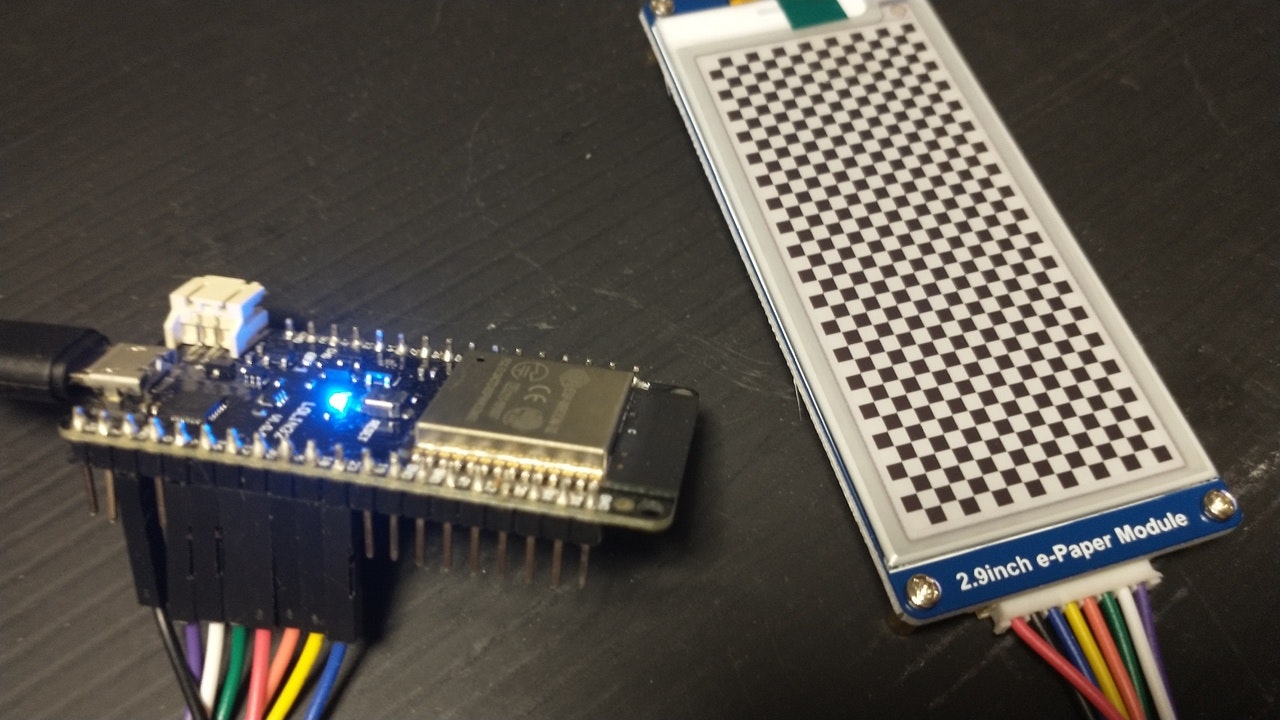
今回の実行結果
フォント情報などを使わないデモのため、代わりにチェッカー模様を表示しています。
目的
複雑な e-Paper の制御を e-Paper へのコマンドレベルで理解するため、e-Paper 外部ライブラリにお任せではなく SPI を直接制御して動かしてみます。
また、図形描画や文字描画などのためのグラフィックバッファーの操作については省略し、単に黒と白を描画するために最低限必要な<動く>コードを作成します。
環境
今までの実験と同様です
- WaveShareの電子ペーパーモジュール。
https://www.waveshare.com/wiki/2.9inch_e-Paper_Module_(B) - Arduino 1.8.10
- ESP32
ESP32 モジュール は WEMOS LOLIN32 を使いました。
「WEMOS LOLIN32 の調査」
https://qiita.com/nanbuwks/items/111ee8cd69f3390d866f
配線
今までの実験と同様です
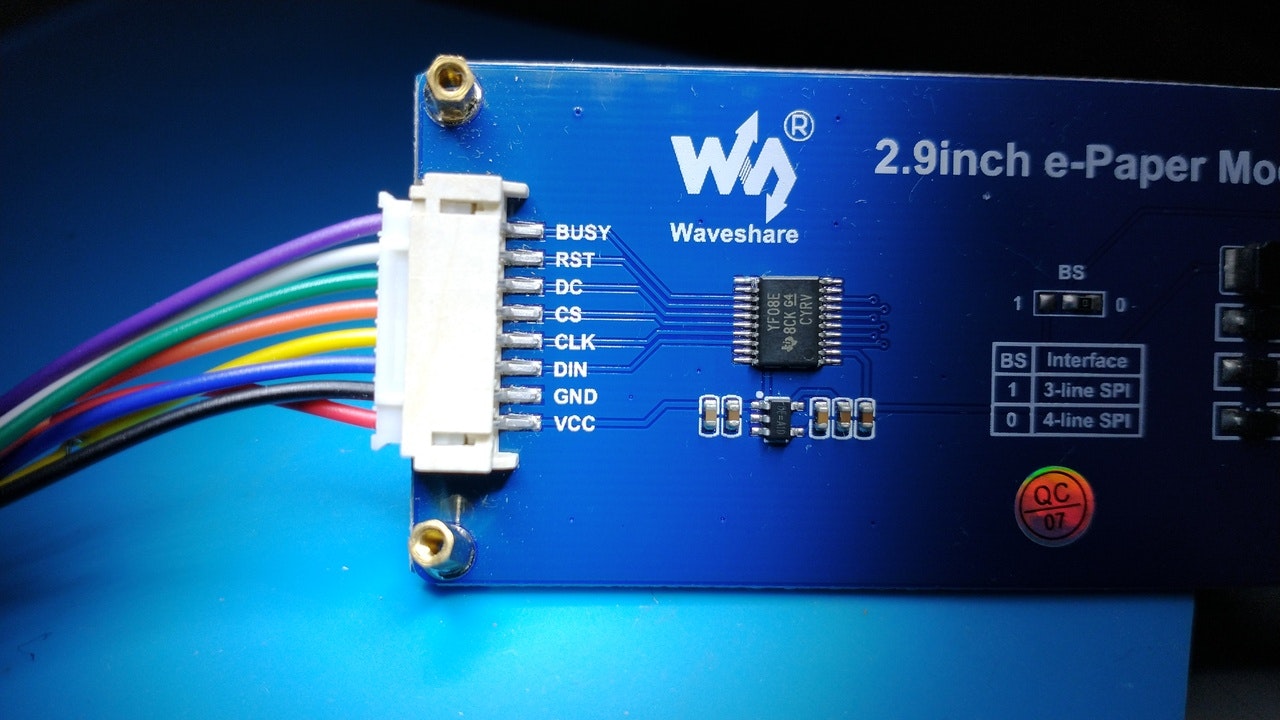
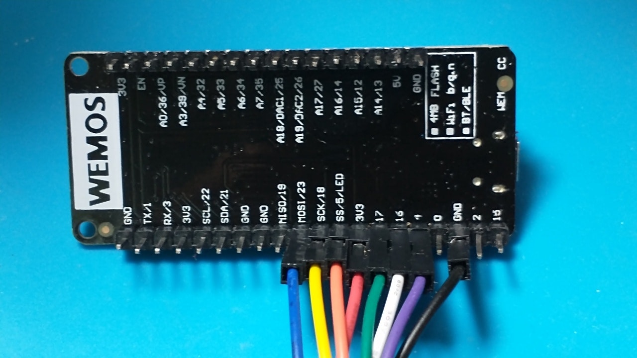
| ESP32 PIN | ESP32 信号名 | WAVESHARE e-Paper 信号名 | ケーブル色 |
|---|---|---|---|
| 4 | 4 | BUSY | 紫 |
| 16 | 16 | RST | 白 |
| 17 | 17 | DC | 緑 |
| 5 | SS/5/LED | CS | 橙 |
| 18 | SCK/18 | CLK | 黄 |
| 23 | MOSI | DIN | 青 |
| GND | GND | GND | 黒 |
| 3V3 | 3.3V | VCC | 赤 |
| 19 | MISO/19 | 接続せず | 接続せず |
元となったコード
waveshare の e-Paper レポジトリがあります。
このうちの、「epd2in9d」を元に作成しました。
https://github.com/waveshare/e-Paper/tree/master/Arduino/epd2in9d
このレポジトリはMITライセンスぽいです。
https://github.com/waveshare/e-Paper/issues/23
なお、今回使うのは2.9inch_e-Paper_Module_(B)なので本来は epd2in9bc を使うはずなのですが、いろんな経緯からこちらを使用しています。
「epd2in9d」はこれ用かな? (あまり調査していません)
https://www.waveshare.net/wiki/2.9inch_e-Paper_HAT_(D)
コード
利用しているのはSPI.hのみインクルードしています。
あとは以下の1ファイルのみで動作します。
# include <SPI.h>

# define RST_PIN         16
# define DC_PIN          17
# define CS_PIN          5
# define BUSY_PIN        4

# define EPD_WIDTH       128
# define EPD_HEIGHT      296

const unsigned char EPD_2IN9D_lut_vcomDC[] = {
    0x00,0x08,0x00,0x00,0x00,0x02,0x60,0x28,0x28,0x00,0x00,0x01,0x00,0x14,0x00,0x00,0x00,0x01,0x00,0x12,
    0x12,0x00,0x00,0x01,0x00,0x00,0x00,0x00,0x00,0x00,0x00,0x00,0x00,0x00,0x00,0x00,0x00,0x00,0x00,0x00,
    0x00,0x00,0x00,0x00,
};
const unsigned char EPD_2IN9D_lut_ww[] = {
    0x40,0x08,0x00,0x00,0x00,0x02,0x90,0x28,0x28,0x00,0x00,0x01,0x40,0x14,0x00,0x00,0x00,0x01,0xA0,0x12,
    0x12,0x00,0x00,0x01,0x00,0x00,0x00,0x00,0x00,0x00,0x00,0x00,0x00,0x00,0x00,0x00,0x00,0x00,0x00,0x00,
    0x00,0x00,
};
const unsigned char EPD_2IN9D_lut_bw[] = {
    0x40,0x17,0x00,0x00,0x00,0x02,0x90,0x0F,0x0F,0x00,0x00,0x03,0x40,0x0A,0x01,0x00,0x00,0x01,0xA0,0x0E,
    0x0E,0x00,0x00,0x02,0x00,0x00,0x00,0x00,0x00,0x00,0x00,0x00,0x00,0x00,0x00,0x00,0x00,0x00,0x00,0x00,
    0x00,0x00,
};
const unsigned char EPD_2IN9D_lut_wb[] = {
    0x80,0x08,0x00,0x00,0x00,0x02,0x90,0x28,0x28,0x00,0x00,0x01,0x80,0x14,0x00,0x00,0x00,0x01,0x50,0x12,
    0x12,0x00,0x00,0x01,0x00,0x00,0x00,0x00,0x00,0x00,0x00,0x00,0x00,0x00,0x00,0x00,0x00,0x00,0x00,0x00,
    0x00,0x00,
};
const unsigned char EPD_2IN9D_lut_bb[] = {
    0x80,0x08,0x00,0x00,0x00,0x02,0x90,0x28,0x28,0x00,0x00,0x01,0x80,0x14,0x00,0x00,0x00,0x01,0x50,0x12,
    0x12,0x00,0x00,0x01,0x00,0x00,0x00,0x00,0x00,0x00,0x00,0x00,0x00,0x00,0x00,0x00,0x00,0x00,0x00,0x00,
    0x00,0x00,
};

void SendCommand(unsigned char command)
{
    digitalWrite(DC_PIN, LOW);
    SPI.transfer(command);
}
void SendData(unsigned char data)
{
    digitalWrite(DC_PIN, HIGH);
    SPI.transfer(data);
}
void WaitUntilIdle(void)
{
    char busy;
    do {
        SendCommand(0x71);
        busy = digitalRead(BUSY_PIN);
        busy =!(busy & 0x01);
    } while(busy);
    delay(200);
}
void SetFullReg(void)
{
    SendCommand(0X50);      //VCOM AND DATA INTERVAL SETTING
    SendData(0xb7);   //WBmode:VBDF 17|D7 VBDW 97 VBDB 57   WBRmode:VBDF F7 VBDW 77 VBDB 37  VBDR B7

    unsigned int count;
    SendCommand(0x20);
    for(count=0; count<44; count++) {
        SendData(EPD_2IN9D_lut_vcomDC[count]);
    }

    SendCommand(0x21);
    for(count=0; count<42; count++) {
        SendData(EPD_2IN9D_lut_ww[count]);
    }

    SendCommand(0x22);
    for(count=0; count<42; count++) {
        SendData(EPD_2IN9D_lut_bw[count]);
    }

    SendCommand(0x23);
    for(count=0; count<42; count++) {
        SendData(EPD_2IN9D_lut_wb[count]);
    }

    SendCommand(0x24);
    for(count=0; count<42; count++) {
        SendData(EPD_2IN9D_lut_bb[count]);
    }
}
void TurnOnDisplay(void)
{
    SendCommand(0x12);     //DISPLAY REFRESH
    delay(10);     //!!!The delay here is necessary, 200uS at least!!!
    WaitUntilIdle();
}
void setup()
{
    // put your setup code here, to run once:
    Serial.begin(115200);
    pinMode(CS_PIN, OUTPUT);
    pinMode(RST_PIN, OUTPUT);
    pinMode(DC_PIN, OUTPUT);
    pinMode(BUSY_PIN, INPUT);
    SPI.begin();
    SPI.beginTransaction(SPISettings(2000000, MSBFIRST, SPI_MODE0));

    digitalWrite(RST_PIN, HIGH);
    delay(200);
    digitalWrite(RST_PIN, LOW);    // module reset
    delay(10);
    digitalWrite(RST_PIN, HIGH);
    delay(200);
    digitalWrite(CS_PIN, LOW);

    //POWER SETTING
    SendCommand(0x01);
    SendData(0x03);
    SendData(0x00);
    SendData(0x2b);
    SendData(0x2b);
    SendData(0x03);

    SendCommand(0x06);  //boost soft start
    SendData(0x17);     //A
    SendData(0x17);     //B
    SendData(0x17);     //C

    SendCommand(0x04);
    WaitUntilIdle();

    SendCommand(0x00);  //panel setting
    SendData(0xbf);     //LUT from OTP,128x296
    SendData(0x0e);     //VCOM to 0V fast

    SendCommand(0x30);  //PLL setting
    SendData(0x3a);     // 3a 100HZ   29 150Hz 39 200HZ 31 171HZ

    SendCommand(0x61);  //resolution setting
    SendData(EPD_WIDTH);
    SendData((EPD_HEIGHT >> 8) & 0xff);
    SendData(EPD_HEIGHT & 0xff);

    SendCommand(0x82);  //vcom_DC setting
    SendData(0x28);

    Serial.println("e-Paper initialized.");
    int w, h;
    w = (EPD_WIDTH % 8 == 0)? (EPD_WIDTH / 8 ): (EPD_WIDTH / 8 + 1);
    h = EPD_HEIGHT;
    SendCommand(0x10);
    for (int j = 0; j < h; j++) {
        for (int i = 0; i < w; i++) {
            SendData(0x00);
        }
    }
//    SendCommand(0x13);
//    for (int j = 0; j < h; j++) {
//        for (int i = 0; i < w; i++) {
//            SendData(0xFF);
//        }
//    }
    SendCommand(0x13);
    for (int j = 0; j < h; j++) {
        for (int i = 0; i < w; i++) {
            if ( 0 == ( j / 8 ) % 2 ){
               SendData(0x00);
               SendData(0xFF);
            } else {
               SendData(0xFF);
               SendData(0x00);
            }
        }
        j++;
    }
    Serial.println("e-Paper cleared");
    SetFullReg();
    TurnOnDisplay();

    SendCommand(0X50);
    SendData(0xf7);
    SendCommand(0X02);    //power off
    WaitUntilIdle();
    SendCommand(0X07);    //deep sleep
    SendData(0xA5);

    digitalWrite(RST_PIN, LOW);
}

void loop()
{

}
ハイライト
何点かに絞ってコードを読み込んでいきます。
該当初期化ルーチン
waveshare のデータシートから。左は2.9inch e-Paper Module (B)のもの。右は2.9inch e-Paper HAT (D)のもの。
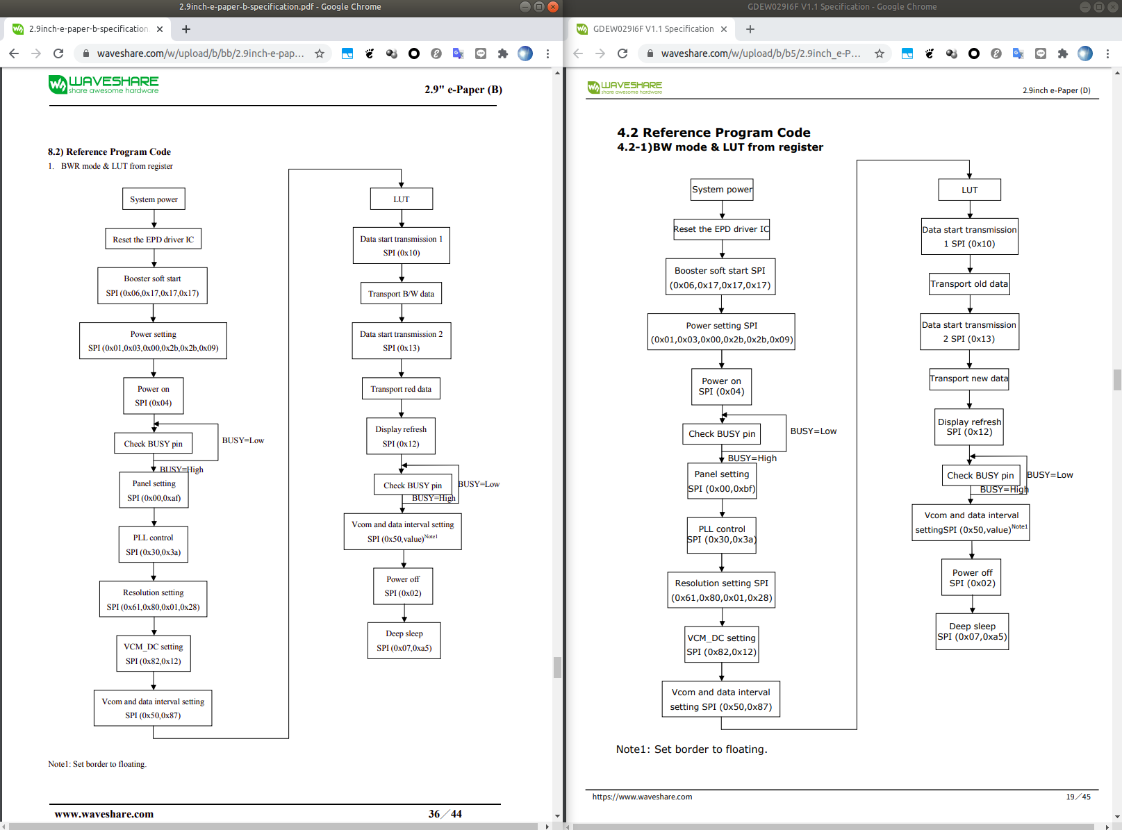
右側のタイトルが「GDEW029I6F V1.1 Specification」となってますね。
GDEW029I6F は GooDisplay の 2.9 inch flexible 4 grayscale e ink display module e paper display
で、
http://www.e-paper-display.com/products_detail/productId=411.html
から IC Driver のリンクを辿ると
IL0373 だそうです。
SPIの設定
Waveshare のインターフェースボードにBSジャンパーがある。
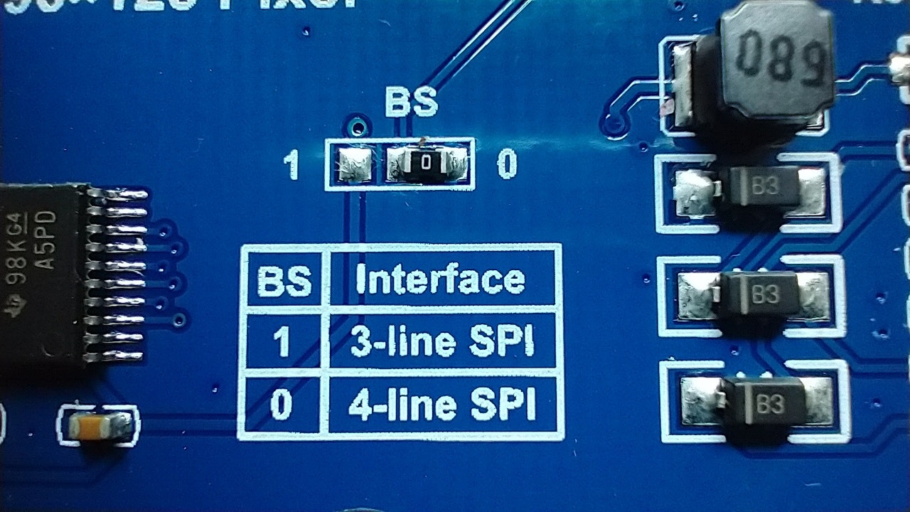
デフォルトでは 4-line SPI に設定されている。
4-line SPI とは、データシート
http://www.good-display.com/public/html/pdfjs/viewer/viewernew.html?file=https://v4.cecdn.yun300.cn/100001_1909185148/GDEH029Z13.pdf
を読むと DC 信号線を使ってCommandとDataのバイト境界、ないしCommandとデータリードの境界を示す方法。
3-line SPI は、SPIでDC信号線の代わりに
Command Startbit として 0,
Data Startbit ないしデータリードの Startbit として 1 となる DC bit を付加する方法らしい。
したがって、 Command/Data送出時において 4-line SPI は 8bit データ単位、3-line SPI は 9bit データ単位となることになる。
コードは 4-line SPI なので例えばコマンド送出するときは以下のようにしてDCラインをLOWにして送出している
void SendCommand(unsigned char command)
{
    digitalWrite(DC_PIN, LOW);
    SPI.transfer(command);
}
BUSY チェック
初期化フロー中に BUSY ピンのチェックがあります。
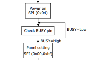
該当コードはこれです
void WaitUntilIdle(void)
{
    char busy;
    do {
        SendCommand(0x71);
        busy = digitalRead(BUSY_PIN);
        busy =!(busy & 0x01);
    } while(busy);
    delay(200);
}