この記事は、「#NervesJP Advent Calendar 2019」 の21日目です。
昨日は @32hero さんの「Why Nerves|>Nervesを使う理由探し」でした。
はじめに
Elixirを使って、RaspberryPiのハードウェア制御の練習をしてみました。
今回は、Elixir CircuitsのI2C制御サンプルを使って、IOエキスパンダICのMCP23017を制御してみます。
※Nervesでないのは、Ubuntu環境が今、手元に無いため・・・ごめんなさい!!
動作環境
ここでのハードウェア環境は、以下を想定しています。
- Raspberry Pi 3+
- Raspbian Buster (2019年9月版)
- Elixir 1.9.4
コマンドライン
~ $ uname -a
Linux RaspberryPi 4.19.75-v7+ #1270 SMP Tue Sep 24 18:45:11 BST 2019 armv7l GNU/Linux

~ $ iex
Erlang/OTP 22 [erts-10.4] [source] [smp:4:4] [ds:4:4:10] [async-threads:1] [hipe]

Interactive Elixir (1.9.4) - press Ctrl+C to exit (type h() ENTER for help)
iex(1)>
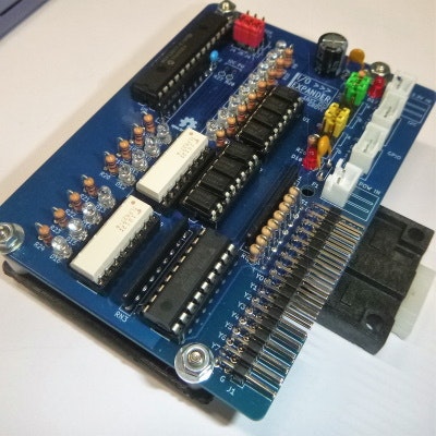
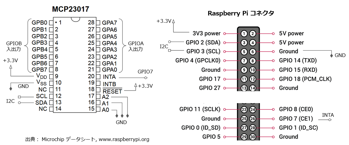
回路
RaspberryPiとMCP23017の接続
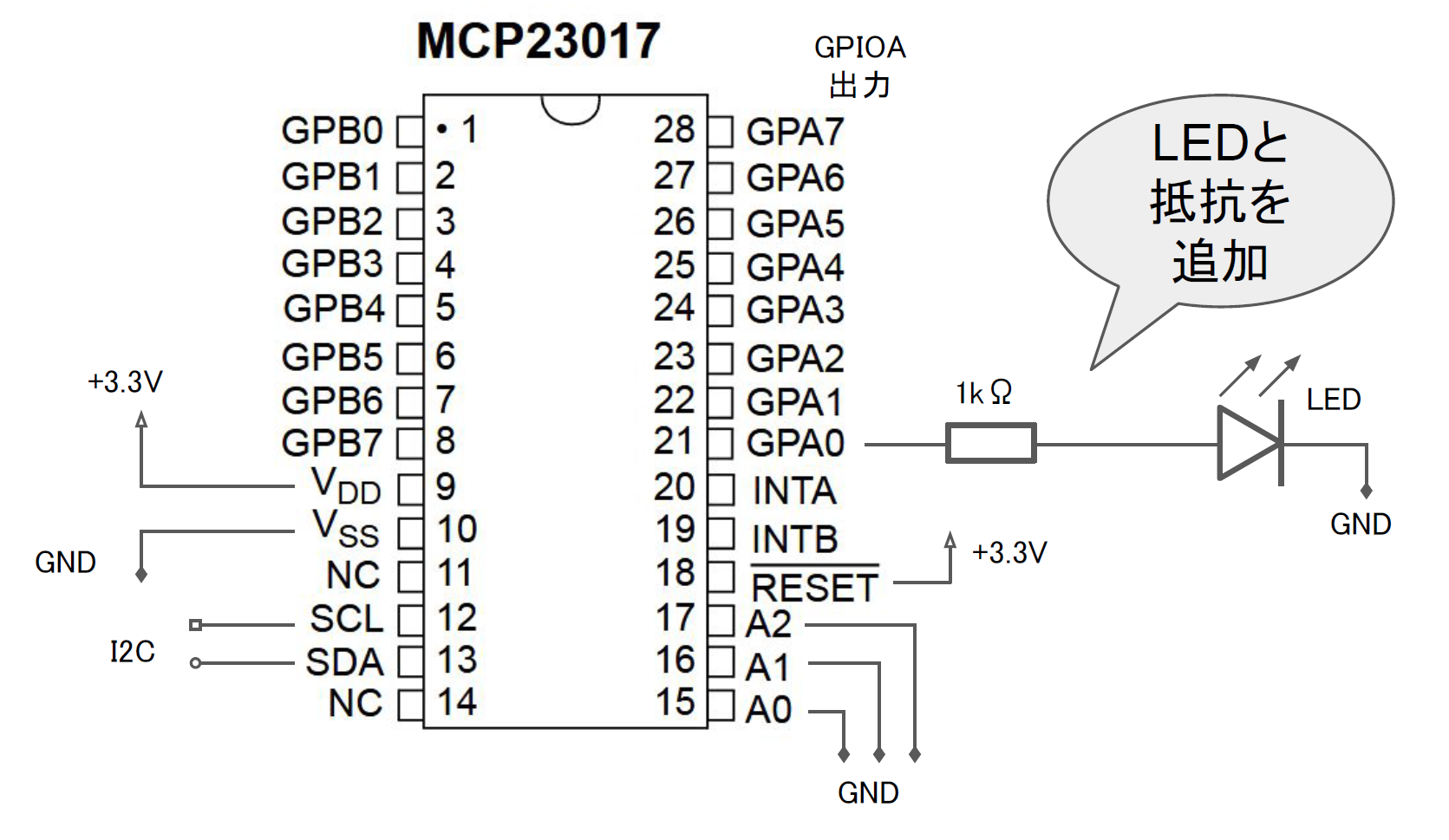
MCP23017とLEDの接続
プログラムの下準備
I2Cの制御に必要なパッケージをインストールします。
コマンドライン
pi@raspberrypi:~ $ sudo apt install i2c-tools -y
I2C経由でMCP23017と通信できているか確認します。
コマンドライン
pi@raspberrypi:~ $ sudo i2cdetect -r -y 1
     0  1  2  3  4  5  6  7  8  9  a  b  c  d  e  f
00:          -- -- -- -- -- -- -- -- -- -- -- -- --
10: -- -- -- -- -- -- -- -- -- -- -- -- -- -- -- --
20: 20 -- -- -- -- -- -- -- -- -- -- -- -- -- -- --
30: -- -- -- -- -- -- -- -- -- -- -- -- -- -- -- --
40: -- -- -- -- -- -- -- -- -- -- -- -- -- -- -- --
50: -- -- -- -- -- -- -- -- -- -- -- -- -- -- -- --
60: -- -- -- -- -- -- -- -- -- -- -- -- -- -- -- --
70: -- -- -- -- -- -- -- --
回路図の通りに接続した場合(A0, A1, A2 = LOW となっている)MCP23017はアドレス0x20に割り当てされます。
MCP23017の制御方法
コマンドの構成は<<レジスタ名, 設定値>>です。
- 初期化コマンドを送る
- MCP23017のPORTAを、出力に設定
<<0x00, 0x00>> - (入力にする場合は
<<0x00, 0xff>>)
- 出力のON/OFFの指令を送る
- PORTAの0~7chをON
<<0x12, 0xff>> - PORTAの0~7chをOFF
<<0x12, 0x00>>
MCP23017の主要コマンド
レジスタ名の
*Aは、MCP23017のGPA0~7。
*Bは、MCP23017のGPB0~7に対応します。
| レジスタ名 | 値 | 機能 |
|---|---|---|
| IODIRA | 0x00 | 入出力方向 (0: 出力 1:入力) |
| IODIRB | 0x01 | 〃 |
| GPIOA | 0x12 | 出力レジスタ (GPIOの値) |
| GPIOB | 0x13 | 〃 |
プログラム例
ElixirでI2Cを制御する
基本構文
I2C.write(ref, 0x20, <<0x12, 0xff>>)
| 引数 | 役割 | 例文 |
|---|---|---|
| 第2 | 送信先のI2Cアドレス | 0x20(MCP23017のデフォルトアドレス) |
| 第3 | コマンド | 0x12(GPIOAの出力レジスタ)、0xff(8ch全部出力とする) |
準備
コマンドライン
~$ git clone https://github.com/elixir-circuits/circuits_i2c.git
~$ cd circuits_i2c/lib
~/circuits_i2c/lib $ touch circuits_i2c.ex
空のソースファイルcircuits_i2c.exを作っておきます。
ソースコード
出力・点滅動作
circuit.ex
defmodule Circuits do

    # "L" Chika
    def loop1(start, count_up, sleep_msec) do
        Stream.iterate( start, &( &1 + count_up ) ) |>
        Enum.map( fn count ->

            alias Circuits.I2C
            #I2Cを開く
            {:ok, ref} = I2C.open("i2c-1")

            # 初期化コマンドをI2C経由で送る
            # MCP23017のPORTAを、出力に設定
            I2C.write(ref, 0x20, <<0x00, 0x00>>)

            # PORTAの0~7chをHIGHに切替
            I2C.write(ref, 0x20, <<0x12, 0xff>>)
            :timer.sleep( sleep_msec )
            # PORTAの0~7chをLOWに切替
            I2C.write(ref, 0x20, <<0x12, 0x00>>)
            :timer.sleep( sleep_msec )

            end )
    end


    def main([]) do
        IO.puts "Hello I2C LED..."
        # 処理スタート
        loop1(0, 1, 500)
    end
end
実行
LEDが500msおきに点滅します。
コマンドライン
~/circuits_i2c $  mix run -e "Circuits.main([])"
Hello I2C LED...
Grove規格の互換ボード
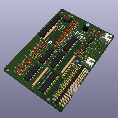
Grove規格(I2C)互換のボードを作ってみました。
※12/21時点、まだ公開できてないです、すみません!!
GitHub
参考資料
- カウンター付き無限ループの書き方