これは Pololu 3pi Robot User’s Guide ≫ 5.b. Power management の非公式日本語訳です。
目次
前: 5.a. Batteries
次: 5.c. Motors and Gearboxes
5.b. Power management
Battery voltage drops as the batteries are used up, but many electrical components require a specific voltage. A special kind of component called a voltage regulator helps out by converting the battery voltage to a constant, specified voltage. For a long time, 5 V has been the most common regulated voltage used in digital electronics; this is also called TTL level. The microcontroller and most of the circuitry in the 3pi operate at 5 V, so voltage regulation is essential. There are two basic types of voltage regulators:
バッテリは使うほど電圧は下がりますが多くの電子部品は特定の電圧を必要とします。電圧レギュレータと呼ばれる特殊な電子部品はバッテリ電圧を一定の指定された電圧に変換する助けとなります。長い間、5Vは最も一般的な安定化電圧としてデジタル電子機器で使われてきました。これはTTLレベルとも呼ばれます。3piのマイコンとほとんどの回路は5Vで動作するため、電圧調整は必要不可欠です。電圧レギュレータには2つの基本的なタイプがあります。
-
Linear regulators use a simple feedback circuit to vary how much energy is passed through and how much is discarded. The regulator produces a lower output voltage by dumping unneeded energy. This wasteful, inefficient approach makes linear regulators poor choices for applications that have a large difference between the input and output voltages, or for applications that require a lot of current. For example, 15 V batteries regulated down to 5 V with a linear regulator will lose two-thirds of their energy in the linear regulator. This energy becomes heat, so linear regulators often need large heat sinks, and they generally don’t work well with high-power applications.
-
Switching regulators turn power on and off at a high frequency, filtering the output to produce a stable supply at the desired voltage. By carefully redirecting the flow of electricity, switching regulators can be much more efficient than linear regulators, especially for high-current applications and large changes in voltage. Also, switching regulators can convert low voltages into higher voltages! A key component of a switching regulator is the inductor, which stores energy and smooths out current; on the 3pi, the inductor is the gray block near the ball caster labeled “100”. A desktop computer power supply also uses switching regulators: peek through the vent in the back of your computer and look for a donut-shaped piece with a coil of thick copper wire wrapped around it – that’s the inductor.
-
リニアレギュレータは単純なフィードバック回路を使用して、通過させるエネルギー量と捨てるエネルギー量を変化させます。このレギュレータは、不必要なエネルギーを捨てて低い出力電圧を生成します。この無駄で非効率なアプローチにより、入力電圧と出力電圧の差が大きいアプリケーションや多くの電流を必要とするアプリケーションには、リニアレギュレータは適していません。例えば、リニアレギュレータによって15Vバッテリを5Vに調整すると、リニアレギュレータ内で3分の2のエネルギーを失います。このエネルギーは熱になるため、リニアレギュレータは大きなヒートシンクを必要とすることが多く、一般的に高電力アプリケーションではうまく動きません。
-
スイッチングレギュレータは高速に電源をオンオフし、望んだ電圧で安定した供給を生み出す為に出力をフィルタリングします。電気の流れを慎重にリダイレクトすることにより、特に高電流アプリケーションや電圧変化が大きい場合に、スイッチングレギュレータはリニアレギュレータよりはるかに高効率にできます。また、スイッチングレギュレータは低い電圧を高い電圧に変換することもできます!スイッチングレギュレータのキー部品は、エネルギーを蓄えて電流をスムーズに出力するインダクタ(訳注:コイル)です。3piでは、"100"とラベル付けされたボールキャスター近くのグレーブロックがインダクタです。デスクトップコンピュータの電源供給にもスイッチングレギュレータが使われています。コンピュータの背面の通気口を覗き見ると太い銅線が巻きつけられたドーナッツ形状のコイルが見えます。それがインダクタです。
The power management subsystem built into the 3pi is shown in this block diagram:
このブロック図は3piに組み込まれている電力管理サブシステムを示したものです。
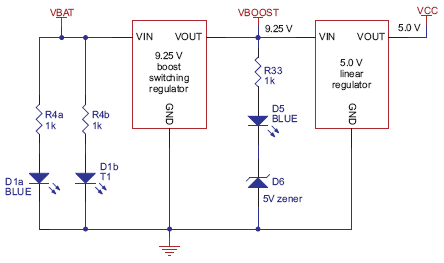
The voltage of 4 x AAA cells can vary between 3.5 – 5.5 V (and even to 6 V if alkalines are used). This means it’s not possible simply to regulate the voltage up or down to get 5 V. Instead, in the 3pi, a switching regulator first boosts the battery voltage up to 9.25 V (Vboost), and a linear regulator regulates Vboost back down to 5 V (VCC). Vboost powers the motors and the IR LEDs in the line sensors, while VCC is used for the microcontroller and all digital signals.
単3電池4本の電圧は3.5~5.5Vの間で変動します(アルカリ電池の場合は6Vまで)。これは5Vを得るための電圧の上げ下げの調整が単純にはできないことを意味します。代わりに、3piでは、最初にスイッチングレギュレータでバッテリ電圧を9.25V(Vboost)まで昇圧し、リニアレギュレータでVboostを5V(VCC)まで戻します。Vboostはモーターとラインセンサ内の赤外線LEDを駆動し、同時にVCCはマイコンとすべてのデジタル信号用に使われます。
Using Vboost for the motors and sensors gives the 3pi three unique performance advantages over typical robots, which use battery power directly:
モーターとセンサ用にVboostを使用する3piは、バッテリ電源を直接使用する典型的なロボットに比べて3つの優れた特徴があります。
-
First, a higher voltage means more power for the motors, without requiring more current and a larger motor driver.
-
Second, since the voltage is regulated, the motors will run the same speed as the batteries drop from 5.5 down to 3.5 V. You can take advantage of this when programming your 3pi, for example by calibrating a 90° turn based on the amount of time that it takes.
-
Third, at 9.25 V, all five of the IR LEDs can be powered in series so that they consume the lowest possible amount of power. (Note that you can switch the LEDs on and off to save even more power.)
-
第1に、高い電圧はモーターの高出力を意味し、そこに大きな電流と大きなモータードライバを必要としません。
-
第2に、電圧が調整されているため、バッテリが5.5Vから3.5Vに低下したとしても、モーターは同じ速度で駆動するでしょう。3piに書き込むときもこのアドバンテージを得られます。例えば、モーターの駆動時間に基づいた90度の回転を校正すること(キャリブレーション)です。
-
第3に、9.25Vで全5つの赤外線LEDに直列に給電することができるため、最小限の電力消費量となります。(LEDのオンとオフの切り替えで、さらに電力を節約できることに留意してください。)
One other interesting thing about this power system is that instead of gradually running out of power like most robots, the 3pi will operate at maximum performance until it suddenly shuts off. This can take you by surprise, so you might want your 3pi to monitor its battery voltage.
この電力システムについてのもう1つの興味深いことは、多くのロボットのように電源が徐々に切れるのではなく、突然停止するまでは最大性能で動作しようとします。これはあなたを驚かせるかもしれないため、3piでバッテリ電圧をモニタした方が良いでしょう。
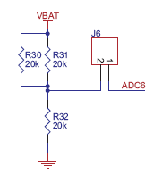
A simple circuit for monitoring battery voltage is built in to the 3pi. Three resistors, shown in the circuit at right, comprise a voltage divider that outputs a voltage equal to two-thirds of the battery voltage, which will always be safely below the main microcontroller’s maximum analog input voltage of 5 V. For example, at a battery voltage of 4.8 V, the battery voltage monitor port ADC6 will be at a level of 3.2 V. Using 10-bit analog-to-digital conversion, where 5 V is read as a value of 1023, 3.2 V is read as a value of 655. To convert it back to the actual battery voltage, multiply this number by 5000 mV×3/2 and divide by 1023. This is handled conveniently by the read_battery_millivolts_3pi() function (provided in the Pololu AVR Library; see Section 6 for more information), which averages ten samples and returns the battery voltage in mV:
バッテリ電圧をモニタするための単純な回路が3piに組み込まれています。下の回路図に示す3つの抵抗は、バッテリ電圧の3分の2に等しい電圧を出力する分圧回路を構成します。これはメインマイコンの最大アナログ入力電圧の5Vを下回り、常に安全です。例えば、4.8Vのバッテリ電圧の場合バッテリ電圧モニタポートのADC6は3.2Vの電圧になります。5Vを1023の値として読み取る10bitのA/D変換を用いると、3.2Vは655の値として読み取れます。これを実際のバッテリ電圧に戻すためには、この数値に5000mV×(3/2)を掛けて1023で割ります。これは、10回のサンプリング結果の平均をとりバッテリ電圧をmVで返すread_battery_millivolts_3pi()関数によって取り扱いやすくなります。(Pololu AVR Library によって提供されます。詳細はSection 6を参照してください)
unsigned int read_battery_millivolts_3pi()
{
    return readAverage(6,10)*5000L*3/2/1023;
}