はじめに
この記事はロボティクスアドベントカレンダー6日目の記事です。
また、自分の勉強も兼ねて様々な言語、通信手法などを試しながらロボットシステムを作っていくシリーズの4つ目の記事です。
- 1つ目の記事:【Python/ロボティクス】差動二輪ロボットの簡易シミュレータを作ってみる
- 2つ目の記事:【Python/numpy】Numpyで2次元の同次変換行列を扱う
- 3つ目の記事:【Python/ロボティクス】シミュレータに長さの単位「メートル」と解像度を導入する
最初の記事でロボットのシミュレータを作ってみたので、それに環境情報を取得できるセンサーを追加していきましょう。
この記事では2次元のLiDARを扱います。LiDARは移動ロボットの自己位置推定や地図作成に使用され、今では必要不可欠なセンサといってもいいでしょう。
具体的な製品としては例えば以下のようなものが挙げられ、ロボットによく使用されています。今回はこのLiDARのパラメータを使用したいと思います。
今回実装するLiDARはこの動画の赤い線です。
ソースコードはこのリポジトリのadd-lidarブランチにあります。
環境
以下の環境で動作を確認しています。
また、Pythonのライブラリについてはプロジェクト内にpyproject.tomlファイルがあります。
| 項目 | バージョン |
|---|---|
| Ubuntu | 24.04 |
| Python | 3.12.3 |
LiDARの実装準備:抽象化したクラス
複数種類のセンサを使うことを想定して、センサのクラスの親クラスを定義します。ここでは2つのクラスを用意しました。
1.センサの仕様のクラス
この親クラスには今は最大値最小値しかありませんが、例えばLiDARであれば光線の数や間隔、超音波センサであれば加味する視野角などをこのクラスを継承して追加していく想定です。
2.センサ本体のクラス
センサの測定はロボットの位置と環境のクラスであるWorldを渡して、ロボットの視点からWorld内の障害物を取得して測定を行います。
その結果はdistancesにアクセスすることで取得します。
LiDARの処理の実装
LiDAR仕様
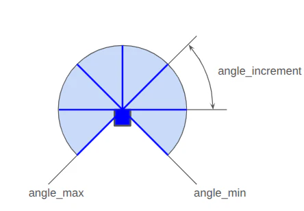
LiDARのセンサの仕様としてデータの処理などに必要なものとして、最小/最大計測角度(angle_min/max)、隣り合う光線と光線の角度の差(angle_increment)、最小/最大検出距離があります。それらをパラメータとして指定します。
イメージとしては以下の図のようになります。
中心の青い四角形がLiDAR本体を表していて、6本の青い線の光線がビームを示しています。
この場合、angle_min=-1/4π[rad], angle_min=5/4π[rad], angle_increment=1/4π[rad]になります。
実際はangle_incrementはもっともっと多く、数百本以上になり、細かくデータを取得することができます。
LiDARのデータ処理本体
LiDARのシミュレーションのコード本体は以下のようになります。
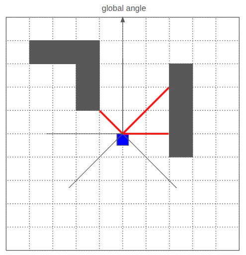
cast_ray関数内で、LiDARのビーム1本に対して、Worldの解像度ずつWorldクラスの障害物を参照して障害物があるかないかを確認します。障害物を検出したらそこまでの距離、最大検出距離まで障害物を検出しなかったらmath.infを返すようにしています。
以下のようなイメージで、障害物があった場合は赤線の距離を返します。
class LiDAR(SensorInterface):
    def __init__(self, specification: LiDARSpecifications) -> None:
        self._specification = specification
        self._distances: list[float] = []

    @property
    def distances(self) -> list[float]:
        return self._distances

    @property
    def specifications(self) -> LiDARSpecifications:
        return self._specification

    def measure(self, robot_pose: pose_util.Pose2D, world: world.World) -> None:
        self._distances = []
        for i in range(self._specification.num_beams):
            beam_angle = self._specification.angle_min + i * self._specification.angle_increment
            global_angle = robot_pose.theta + beam_angle - math.pi / 2
            distance = self._cast_ray(
                robot_pose.x,
                robot_pose.y,
                global_angle,
                world,
            )
            self._distances.append(distance)

    def _cast_ray(self, x: float, y: float, angle: float, world: world.World) -> float:
        dx = math.cos(angle)
        dy = math.sin(angle)

        grid_x, grid_y = world.world_to_grid(x, y)
        if world.is_obstacle(grid_x, grid_y):
            return 0.0

        current_x = x
        current_y = y
        for i in range(int(self._specification.range_max / world.resolution)):
            current_x += dx * world.resolution
            current_y += dy * world.resolution
            grid_x, grid_y = world.world_to_grid(current_x, current_y)
            if world.is_obstacle(grid_x, grid_y):
                distance = math.sqrt((current_x - x) ** 2 + (current_y - y) ** 2)
                return distance
        return math.inf
ロボットに搭載する
ここではLiDAR単体ではなく、移動ロボットに載せてデータを取得することにしましょう。
そこで考慮しなければならないのが、ロボットとセンサーの相対位置と姿勢です。このシュミレータではロボットの中心をロボットの位置として扱っていますが、実際にセンサーを取り付けるとしたらロボットの中心から前方向にXmm、複数付けるとしたら前後にYmm離れたところに搭載することになると思います。物理的にそうせざるを得ないですよね。
そこで本シミュレータでは複数センサを搭載することを加味して、名前付きでロボットに搭載するセンサを管理することとします。
Robotクラスにも以下の関数を追加してセンサの処理をできるようにしましょう。
 class Robot:
     def __init__(self, x: float = 10.0, y: float = 10.0, theta: float = 0.0) -> None:
         self._robot_pose = pose_util.Pose2D(x, y, theta)
         self._v = 0.0
         self._omega = 0.0
         self._radius = 0.5

+        self._sensors: list[SensorOnRobot] = []

+    @property
+    def sensors(self) -> list[SensorOnRobot]:
+        return self._sensors

+    def get_sensor(self, name: str) -> SensorOnRobot | None:
+        for sensor_on_robot in self._sensors:
+            if sensor_on_robot.name == name:
+                return sensor_on_robot
+        return None

+    def add_sensor(self, sensor_on_robot: SensorOnRobot) -> None:
+        self._sensors.append(sensor_on_robot)

    def set_velocity(self, linear: float, angular: float) -> None:
        self._v = linear
        self._omega = angular

+    def sense(self, world: world.World) -> None:
+        for sensor_on_robot in self._sensors:
+            sensor_on_robot.sensor.measure(self.get_pose(), world)
...
コード全体は以下を参照ください。
ロボットのシミュレータに統合
以前の記事で作ったシミュレータから呼び出します。
まずはシミュレータ用のビジュアライザーに統合しましょう。
LiDARのデータを設定する関数(set_lidar_specifications)とそれの描画の関数(_draw_lidar)を追加しました。ここではまだ1つのLiDARしか対応していません。
実装を見てもらうとわかるのですが、_draw_lidar内の処理ではまずロボットの向きを計算して、その向きからさらにLiDARの光線の向きを足して環境に対する角度を出して1本1本描画しています。
class SimulatorVisualizer
# ...
    def set_lidar_specifications(
        self, distances: list[float], specifications: sensor.LiDARSpecifications
    ) -> None:
        self._lidar_distances = distances
        self._lidar_specifications = specifications

# ... 中略
    def _draw_lidar(self) -> None:
        if self._lidar_specifications is None:
            return
        for line_id in self._sensor_line_ids:
            self._canvas.delete(line_id)
        self._sensor_line_ids.clear()

        x = self._robot_pose.x
        y = self._robot_pose.y
        theta = self._robot_pose.theta
        xc, yc = self._convert_to_canvas_coodinate(x, y)
        for i, dist in enumerate(self._lidar_distances):
            beam_angle = (
                self._lidar_specifications.angle_min
                + i * self._lidar_specifications.angle_increment
            )
            sensor_angle = theta + beam_angle - math.pi / 2
            x_end = x + dist * math.cos(sensor_angle)
            y_end = y + dist * math.sin(sensor_angle)

            x_end_c, y_end_c = self._convert_to_canvas_coodinate(x_end, y_end)
            line_id = self._canvas.create_line(
                xc, yc, x_end_c, y_end_c, fill="red", dash=(1, 3), width=5
            )
            self._sensor_line_ids.append(line_id)
そしてRobotクラスなどと一緒にSimulatorクラスにも統合しましょう。
import numpy as np

from kk_robotics import pose_util
from kk_robotics.simulator import robot
from kk_robotics.simulator import sensor
from kk_robotics.simulator import vizualizer
from kk_robotics.simulator import world


class Simulator:
    def __init__(
        self,
        world_impl: world.World,
        robot_impl: robot.Robot,
        vizualizer_impl: vizualizer.SimulatorVisualizer,
    ) -> None:
        self._world = world_impl
        self._robot = robot_impl
        self._vizualizer = vizualizer_impl

        self._vizualizer.draw_world(world_impl)

    def set_velocity(self, linear_velocity: float, angular_velocity: float) -> None:
        self._robot.set_velocity(linear_velocity, angular_velocity)

    def get_pose(self) -> pose_util.Pose2D:
        return self._robot.get_pose()

    def get_sensor(self, name: str) -> robot.SensorOnRobot | None:
        return self._robot.get_sensor(name)

    def get_world(self) -> np.ndarray:
        return self._world.grid

    def update(self, dt: float = 0.1) -> None:
        self._robot.update(self._world, dt)
        self._robot.sense(self._world)
        self._vizualizer.set_robot_pose(self._robot.get_pose())

        for sensor_on_robot in self._robot.sensors:
            sensor_interface = sensor_on_robot.sensor
            specification = sensor_on_robot.sensor.specifications
            if isinstance(specification, sensor.LiDARSpecifications):
                self._vizualizer.set_lidar_specifications(sensor_interface.distances, specification)
            else:
                # TODO: support other type
                pass
        self._vizualizer.update()
実行してみると、ロボット前方に円弧状に赤線が描画されます。これは円弧の線を描画しているのではなく、LiDARのビーム1本1本に対して点線を描画しているので結果的に円弧になっているように見えています。
まとめ
文字が多くなりましたが、LiDARの実装を追加してみました。
光線1本1本の角度の計算など、自分で実装してみると理解が深まりました。
ロボティクスアドベントカレンダーの投稿をお待ちしています!